SERVICE MANUAL
US Model
Canadian Model
Korea Model
DCR-PC5
AEP Model
UK Model
DCR-PC4E/PC5E
Australian Model
Chinese Model
DCR-PC5E
E Model
Hong Kong Model
Tourist Model
DCR-PC5/PC5E
SERVICE MANUAL
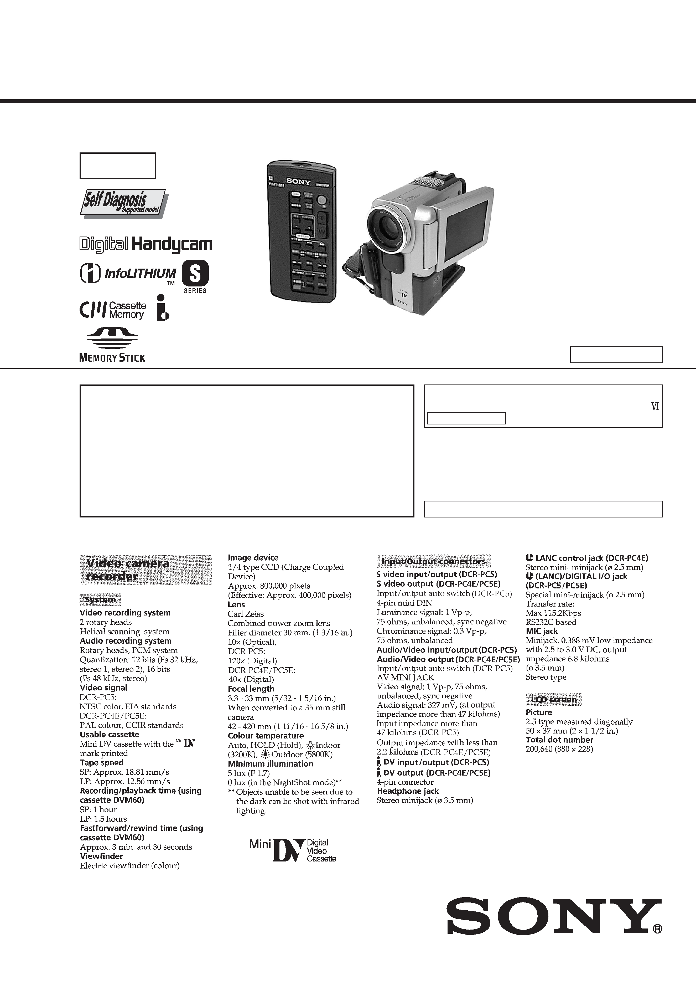
DIGITAL VIDEO CAMERA RECORDER
J MECHANISM
SPECIFICATIONS
DCR-PC5
: NTSC model
DCR-PC4E/PC5E : PAL model
For MECHANISM ADJUSTMENTS, refer to the
"DV MECHANICAL ADJUSTMENT MANUAL
J MECHANISM " (9-929-807-11).
-- Continued on next page --
Level 2
On the VC-245 board
This service manual provides the information that is premised the
circuit board replacement service and not intended repair inside the
VC-245 board.
Therefore, schematic diagram, printed wiring board and electrical parts
list of the VC-245 board are not shown.
The following pages are not shown.
Schematic diagram .......................... Pages 4-17 to 4-54
Printed wiring board ......................... Pages 4-55 to 4-58
Electrical parts list ............................ Pages 6-13 to 6-25
Photo : DCR-PC5 (GRAY)
RMT-811
· Table showing differences is shown on page 3.
DCR-PC4E/PC5/PC5E
RMT-809/811/812
Ver 1.0 2000. 05
-- 2 --
SAFETY-RELATED COMPONENT WARNING!!
COMPONENTS IDENTIFIED BY MARK 0 OR DOTTED LINE WITH
MARK 0 ON THE SCHEMATIC DIAGRAMS AND IN THE PARTS
LIST ARE CRITICAL TO SAFE OPERATION. REPLACE THESE
COMPONENTS WITH SONY PARTS WHOSE PART NUMBERS
APPEAR AS SHOWN IN THIS MANUAL OR IN SUPPLEMENTS
PUBLISHED BY SONY.
ATTENTION AU COMPOSANT AYANT RAPPORT
À LA SÉCURITÉ!
LES COMPOSANTS IDENTIFÉS PAR UNE MARQUE 0 SUR LES
DIAGRAMMES SCHÉMATIQUES ET LA LISTE DES PIÈCES SONT
CRITIQUES POUR LA SÉCURITÉ DE FONCTIONNEMENT. NE
REMPLACER CES COMPOSANTS QUE PAR DES PIÈSES SONY
DONT LES NUMÉROS SONT DONNÉS DANS CE MANUEL OU
DANS LES SUPPÉMENTS PUBLIÉS PAR SONY.
1.
Check the area of your repair for unsoldered or poorly-soldered
connections. Check the entire board surface for solder splashes
and bridges.
2.
Check the interboard wiring to ensure that no wires are
"pinched" or contact high-wattage resistors.
3.
Look for unauthorized replacement parts, particularly
transistors, that were installed during a previous repair. Point
them out to the customer and recommend their replacement.
4.
Look for parts which, through functioning, show obvious signs
of deterioration. Point them out to the customer and
recommend their replacement.
5.
Check the B+ voltage to see it is at the values specified.
6.
Flexible Circuit Board Repairing
· Keep the temperature of the soldering iron around 270°C
during repairing.
· Do not touch the soldering iron on the same conductor of the
circuit board (within 3 times).
· Be careful not to apply force on the conductor when soldering
or unsoldering.
SAFETY CHECK-OUT
After correcting the original service problem, perform the following
safety checks before releasing the set to the customer.
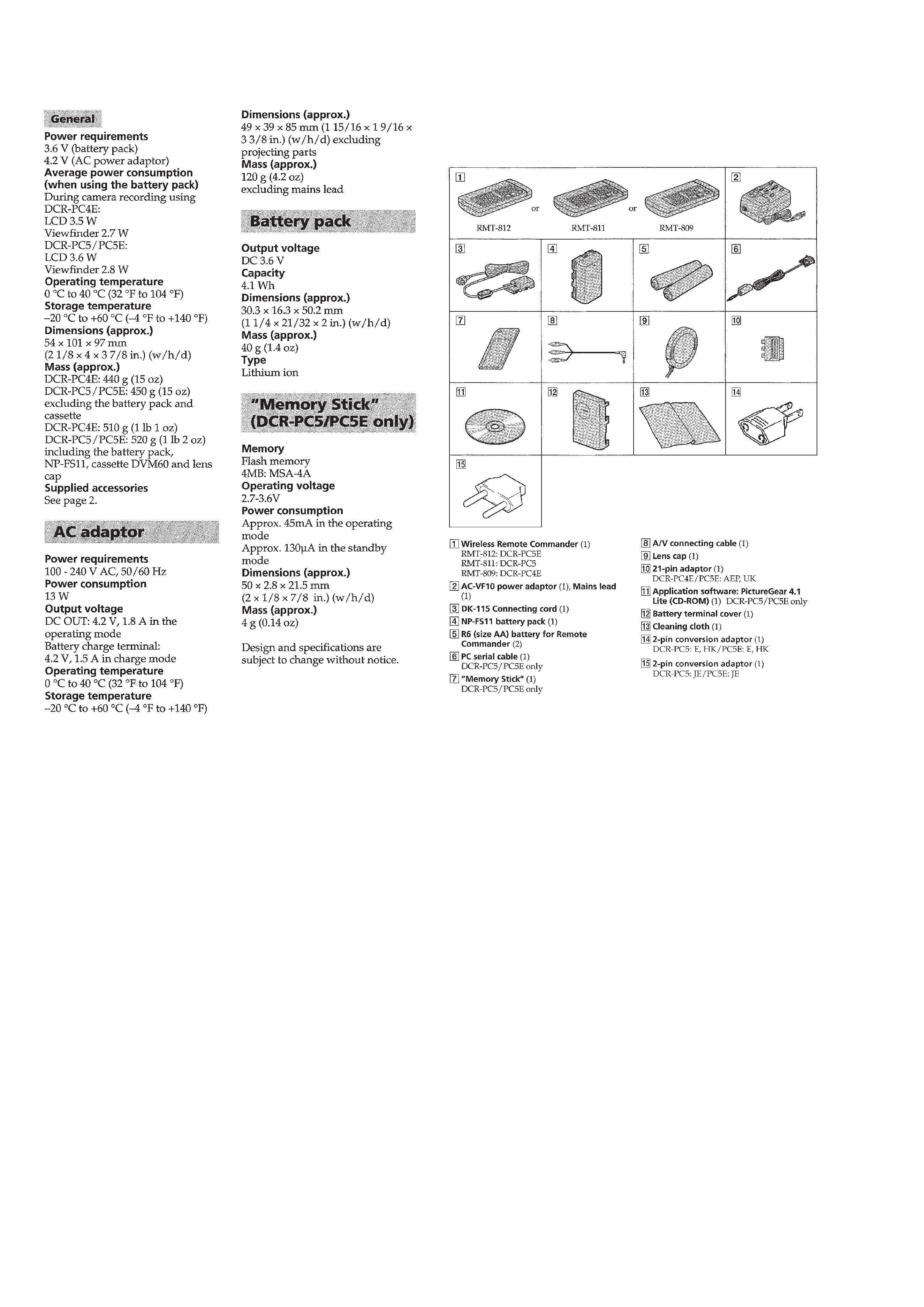
· SUPPLIED ACCESSORIES
Check that the following accessories are supplied with your
camcorder.

-- 3 --
Table for differences of function
Model
Destination
Color system
Remote commander
Digital zoom
MEMORY STICK slot
DIGITAL I/O
(RS232C)
LINE IN
EVF (pixel)
DCR-PC4E
AEP, UK
PAL
RMT-809
40
×
!
!
!
113 K
DCR-PC5
US, CND, E,
HK, KR, JE
NTSC
RMT-811
120
×
a
a
a
180 K
Remark
a: with IC1402 to IC1407 of VC-245 board.
a: with REC button and IC903 of VC-245 board.
Abbreviation
CND: Canadian mode
HK:
Hong Kong model
AUS:
Austrarian model
CN:
Chinese model
JE:
Tourist model
KR:
Korea model
DCR-PC5E
AEP, UK
PAL
RMT-812
40
×
a
a
!
180 K
DCR-PC5E
E, AUS, HK,
CN, JE
PAL
RMT-811
120
×
a
a
a
180 K

-- 4 --
TABLE OF CONTENTS
SERVICE NOTE
1.
POWER SUPPLY DURING REPAIRS ····························· 7
2.
TO TAKE OUT A CASSETTE WHEN NOT EJECT
(FORCE EJECT) ································································ 7
SELF-DIAGNOSIS FUNCTION
1.
SELF-DIAGNOSIS FUNCTION ······································· 8
2.
SELF-DIAGNOSIS DISPLAY ·········································· 8
3.
SERVICE MODE DISPLAY ············································· 8
3-1.
Display Method ·································································· 8
3-2.
Backup No. ········································································· 8
3-3.
End of Display ···································································· 8
4.
SELF-DIAGNOSIS CODE TABLE ··································· 9
1.
GENERAL
Checking supplied accessories ·················································· 1-1
Quick Start Guide ······································································ 1-1
Getting started ··········································································· 1-2
Using this manual ·································································· 1-2
Step 1 Preparing the power supply ········································ 1-2
Charging the battery pack ···················································· 1-2
Installing the battery pack ···················································· 1-3
Connecting to the mains ······················································ 1-4
Step 2 Inserting a cassette ······················································ 1-4
Step 3 Using a touch panel ···················································· 1-4
Recording Basics ····································································· 1-5
Recording a picture ································································ 1-5
Shooting backlit subjects (BACK LIGHT) ·························· 1-6
Shooting in the dark (NightShot/Super NightShot) ············· 1-7
Self-timer recording ····························································· 1-7
END SEARCH ···································································· 1-7
Playback Basics ······································································· 1-8
Playing back a tape ································································ 1-8
Viewing the recording on TV ················································ 1-9
Advanced Recording Operations ············································· 1-10
Recording a still image on a tape Tape Photo recording ··· 1-10
Adjusting the white balance manually ································· 1-11
Using the wide mode ··························································· 1-11
Using the fader function ······················································ 1-11
Using special effects Picture effect ···································· 1-12
Using special effects Digital effect ···································· 1-13
Using the PROGRAM AE function ····································· 1-13
Adjusting the exposure manually ········································ 1-14
Using the spot light-metering mode Flexible Spot Meter ··· 1-14
Focusing manually ······························································· 1-15
Advanced Playback Operations ··············································· 1-15
Playing back a tape with picture effects ······························ 1-15
Playing back a tape with digital effects ······························· 1-16
Enlarging images recorded on tapes PB ZOOM ·············· 1-16
Quickly locating a scene using the zero set memory function ·· 1-16
Searching the boundaries of recorded tape by title
Title search ········································································· 1-17
Searching a recording by date Date search ························ 1-17
Searching for a photo Photo search/Photo scan ················· 1-18
Editing ····················································································· 1-19
Dubbing a tape ····································································· 1-19
Dubbing only desired scenes Digital program editing ······ 1-19
Audio dubbing ····································································· 1-22
Superimposing a title ··························································· 1-23
Making your own titles ························································ 1-24
Labeling a cassette ······························································· 1-25
Customizing Your Camcorder ················································· 1-25
Changing the menu settings ················································· 1-25
Resetting the date and time ·················································· 1-27
"Memory Stick" Operations (DCR-PC5/PC5E only) ············· 1-27
Using a "Memory Stick" introduction ······························· 1-27
Recording still images on "Memory Stick"
Memory photo recording ··················································· 1-29
Superimposing a still picture in the "Memory Stick"
on a moving picture MEMORY MIX ································ 1-30
Recording an image from a mini DV tape as a still image ·· 1-32
Copying still images from a mini DV tape Photo save ······ 1-32
Viewing a still picture Memory photo playback ················ 1-33
Enlarging still images recorded on "Memory Stick"s
Memory PB ZOOM ··························································· 1-34
Playing back images continuously SLIDE SHOW ··········· 1-34
Preventing accidental erasure Image protection ················ 1-35
Deleting images ··································································· 1-35
Writing a print mark PRINT MARK ································· 1-36
Additional Information ···························································· 1-36
Using the viewfinder ···························································· 1-36
Usable cassettes ··································································· 1-36
About i.LINK ······································································· 1-37
Troubleshooting ··································································· 1-38
Self-diagnosis display ·························································· 1-39
Warning indicators and messages ········································ 1-39
Using your camcorder abroad ·············································· 1-40
Maintenance information and precautions ··························· 1-40
Quick Reference ······································································ 1-42
Identifying the parts and controls ········································ 1-42
Quick Function Guide ························································· 1-44
2.
DISASSEMBLY
2-1.
LCD UNIT, PD-126 BOARD ········································· 2-2
2-2.
CABINET (R) BLOCK ASSEMBLY-1 ·························· 2-3
2-3.
CABINET (R) BLOCK ASSEMBLY-2 ·························· 2-4
2-4.
BJ-1 BOARD ··································································· 2-4
2-5.
LENS-EVF BLOCK ASSEMBLY ·································· 2-5
2-6.
MICROPHONE BLOCK, SPEAKER ···························· 2-5
2-7.
VC-245 BOARD ····························································· 2-6
2-8.
MECHANISM DECK ····················································· 2-6
2-9.
CF-75 BOARD, LENS DEVICE (LSV-651B) ··············· 2-7
2-10. HEADPHONE JACK, S TERMINAL,
LITHIUM BATTERY, MEMORY STICK
CONNECTOR (PC5/PC5E MODEL) ···························· 2-8
2-11. NS-12 BOARD, CONTROL SWITCH BLOCK
(PS-30350), CONTROL SWITCH BLOCK (FK-30350) ·· 2-9
2-12. LCD HINGE ASSEMBLY ············································ 2-11
2-13. ATTACHING HARNESSES OF THE LCD HINGE
ASSEMBLY ·································································· 2-12
2-14. CIRCUIT BOARDS LOCATION ································· 2-13
2-15. FLEXIBLE BOARDS LOCATION ······························ 2-14
3.
BLOCK DIAGRAMS
3-1.
OVERALL BLOCK DIAGRAM (1/3)(DCR-PC4E) ······ 3-1
3-2.
OVERALL BLOCK DIAGRAM (1/3)(DCR-PC5/PC5E) · 3-3
3-3.
OVERALL BLOCK DIAGRAM (2/3) ··························· 3-5
3-4.
OVERALL BLOCK DIAGRAM (3/3) ··························· 3-7
3-5.
POWER BLOCK DIAGRAM (1/2) ································ 3-9
3-6.
POWER BLOCK DIAGRAM (2/2) ······························ 3-11
4.
PRINTED WIRING BOARDS AND
SCHEMATIC DIAGRAMS
4-1.
FRAME SCHEMATIC DIAGRAM (1/2) ······················· 4-1
FRAME SCHEMATIC DIAGRAM (2/2) ······················· 4-3
4-2.
PRINTED WIRING BOARDS AND
SCHEMATIC DIAGRAMS ············································ 4-5
· CF-75 (CCD IMAGER)
PRINTED WIRING BOARD ························· 4-7
· NS-12 (REMOTE COMMANDER RECEIVER)
PRINTED WIRING BOARD ······················· 4-11
· CF-75 (CCD IMAGER)(1/2),
NS-12 (REMOTE COMMANDER RECEIVER)
SCHEMATIC DIAGRAM ···························· 4-13
· CF-75 (PITCH, YAW SENSOR)(2/2)
SCHEMATIC DIAGRAM ···························· 4-15

-- 5 --
Shematic diagram and printed wiring board of the
VC-245 board are not shown.
Pages from 4-17 to 4-58 are not shown.
· PO-5 (PANEL OPEN), PR-34 (PANEL REVERSE)
PRINTED WIRING BOARDS ····················· 4-60
· PO-5 (PANEL OPEN), PR-34 (PANEL REVERSE)
SCHEMATIC DIAGRAM ···························· 4-60
· FP-100 (MODE SWITCH). FP-228 (DEW SENSOR),
FP-102 (TAPE TOP/END SENSOR, S/T REEL)
FLEXIBLE BOARDS AND
SCHEMATIC DIAGRAM ···························· 4-61
· CONTROL SWITCH BLOCK (FK-30350)
PRINTED WIRING BOARD ······················· 4-63
· CONTROL SWITCH BLOCK (FK-30350)
SCHEMATIC DIAGRAM ···························· 4-65
· BJ-1 (JACK, BATTERY)
PRINTED WIRING BOARD ······················· 4-67
· BJ-1 (JACK, BATTERY)
SCHEMATIC DIAGRAM ···························· 4-69
· PD-126 (LCD DRIVE)
PRINTED WIRING BOARD ······················· 4-71
· PD-126 (LCD DRIVE)(1/2)
SCHEMATIC DIAGRAM ···························· 4-73
· PD-126 (LCD DRIVE)(2/2)
SCHEMATIC DIAGRAM ···························· 4-75
4-3.
WAVEFORMS ······························································ 4-77
4-4.
MOUNTED PARTS LOCATION ································· 4-82
5.
ADJUSTMENTS
1.
Before starting adjustment ··············································· 5-1
1-1.
Adjusting items when replacing main parts and boards. ··· 5-2
5-1.
CAMERA SECTION ADJUSTMENT ··························· 5-4
1-1.
PREPARATIONS BEFORE ADJUSTMENT
(CAMERA SECTION) ··················································· 5-4
1-1-1. List of Service Tools ························································ 5-4
1-1-2. Preparations ····································································· 5-5
1-1-3. Precaution ········································································ 5-7
1.
Setting the Switch ···························································· 5-7
2.
Order of Adjustments ······················································ 5-7
3.
Subjects ··········································································· 5-7
1-2.
INITIALIZATION OF B, C, D, E, F, 7, 8 PAGE DATA ··· 5-8
1-2-1. INITIALIZATION OF C, D, 8 PAGE DATA ·················· 5-8
1.
Initializing the C, D, 8 Page Data ···································· 5-8
2.
Modification of C, D, 8 Page Data ·································· 5-8
3.
C Page Table ···································································· 5-8
4.
D Page Table ·································································· 5-10
5.
8 Page Table ··································································· 5-11
1-2-2. INITIALIZATION OF B PAGE DATA
(DCR-PC5/PC5E) ························································· 5-12
1.
Initializing the B Page Data ··········································· 5-12
2.
Modification of B Page Data ········································· 5-12
3.
B Page Table ·································································· 5-12
1-2-3. INITIALIZATION OF E, F, 7 PAGE DATA ················· 5-13
1.
Initializing the E, F, 7 Page Data ··································· 5-13
2.
Modification of E, F, 7 Page Data ································· 5-13
3.
F Page Table ·································································· 5-13
4.
E Page Table ·································································· 5-14
5.
7 Page Table ··································································· 5-15
1-3.
CAMERA SYSTEM ADJUSTMENTS ························ 5-16
1.
36MHz Origin Oscillation Adjustment (VC-245 board) ·· 5-16
2.
Zoom Key Center Adjustment ······································· 5-16
3.
HALL Adjustment ························································· 5-17
4.
Flange Back Adjustment (Using Minipattern Box) ······· 5-18
5.
Flange Back Adjustment
(Using Flange Back Adjustment Chart and
Subject More Than 500m Away) ··································· 5-19
5-1.
Flange Back Adjustment (1) ·········································· 5-19
5-2.
Flange Back Adjustment (2) ·········································· 5-19
6.
Flange Back Check ························································ 5-20
7.
Optical Axis Adjustment ··············································· 5-21
8.
Picture Frame Setting ···················································· 5-22
9.
Color Reproduction Adjustment ···································· 5-23
10.
MAX GAIN Adjustment ··············································· 5-24
11.
Auto White Balance & LV Standard Data Input ··········· 5-24
12.
Auto White Balance Adjustment ··································· 5-25
13.
White Balance Check ···················································· 5-26
14.
Mechanical Shutter Adjustment (DCR-PC5/PC5E) ······ 5-27
15.
Steady Shot Check ························································· 5-27
1-4.
COLOR ELECTRONIC VIEWFINDER SYSTEM
ADJUSTMENT ····························································· 5-28
1.
VCO Adjustment (VC-245 board) ································ 5-28
2.
Bright Adjustment (VC-245 board) ······························· 5-29
3.
Contrast Adjustment (VC-245 board) ··························· 5-29
4.
White Balance Adjustment (VC-245 board) ················· 5-30
1-5.
LCD SYSTEM ADJUSTMENT ··································· 5-31
1.
VCO Adjustment (PD-126 board) ································· 5-31
2.
Bright Adjustment (PD-126 board) ······························· 5-32
3.
Black Limit Adjustment (PD-126 board) ······················ 5-32
4.
Contrast Adjustment (PD-126 board) ···························· 5-33
5.
Center Level Adjustment (PD-126 board) ····················· 5-33
6.
V-COM Adjustment (PD-126 board) ···························· 5-34
7.
White Balance Adjustment (PD-126 board) ·················· 5-34
5-2.
MECHANISM SECTION ADJUSTMENT ·················· 5-35
2-1.
HOW TO ENTER RECORD MODE WITHOUT
CASSETTE ··································································· 5-35
2-2.
HOW TO ENTER PLAYBACK MODE WITHOUT
CASSETTE ··································································· 5-35
2-3.
TAPE PATH ADJUSTMENT ········································ 5-35
1.
Preparation for Adjustment ··········································· 5-35
2.
Procedure after operations ············································· 5-35
5-3.
VIDEO SECTION ADJUSTMENTS ··························· 5-36
3-1.
PREPARATIONS BEFORE ADJUSTMENTS ············ 5-36
3-1-1. Equipment Required ······················································ 5-36
3-1-2. Precautions on Adjusting ··············································· 5-37
3-1-3. Adjusting Connectors ···················································· 5-38
3-1-4. Connecting the Equipment ············································ 5-38
3-1-5. Alignment Tapes ···························································· 5-39
3-1-6. Input/Output Level and Impedance ······························· 5-39
3-2.
SYSTEM CONTROL SYSTEM ADJUSTMENT ········ 5-40
1.
Initialization of B, C, D, E, F, 7, 8 Page Data ··············· 5-40
2.
Serial No. Input ····························································· 5-40
2-1.
Company ID Input ························································· 5-40
2-2.
Serial No. Input ····························································· 5-40
3.
Touch Panel Adjustment (VC-245 board) ····················· 5-42
4.
Battery End Check (VC-245 board) ······························ 5-42
3-3.
SERVO AND RF SYSTEM ADJUSTMENT ··············· 5-43
1.
Cap FG Duty Adjustment (VC-245 Board) ··················· 5-43
2.
PLL f0 & LPF f0 Adjustment (VC-245 Board) ·············· 5-43
3.
Switching Position Adjustment (VC-245 Board) ·········· 5-44
4.
AGC Center Level and APC & AEQ Adjustment ········· 5-44
4-1.
Preparations before adjustments ···································· 5-44
4-2.
AGC Center Level Adjustment (VC-245 Board) ·········· 5-44
4-3.
APC & AEQ Adjustment (VC-245 Board) ··················· 5-45
4-4.
Processing after Completing Adjustments ···················· 5-45
3-4.
VIDEO SYSTEM ADJUSTMENTS ····························· 5-46
3-4-1. Base Band Block Adjustments ······································ 5-46
1.
Chroma BPF f0 Adjustment (VC-245 Board) ················ 5-46
2.
S VIDEO OUT Y Level Adjustment (VC-245 Board) ·· 5-46
3.
S VIDEO OUT Chroma Level Adjustment
(VC-245 Board) ····························································· 5-47
4.
VIDEO OUT Y, Chroma Level Check (VC-245 Board) ·· 5-47
3-4-2. BIST Check ·································································· 5-48
1.
Playback System Check ················································ 5-48