DCR-PC1000
US Model
Canadian Model
Korea Model
Japanese Model
DCR-PC1000E
AEP Model
UK Model
Australian Model
Chinese Model
North European Model
Hong Kong Model
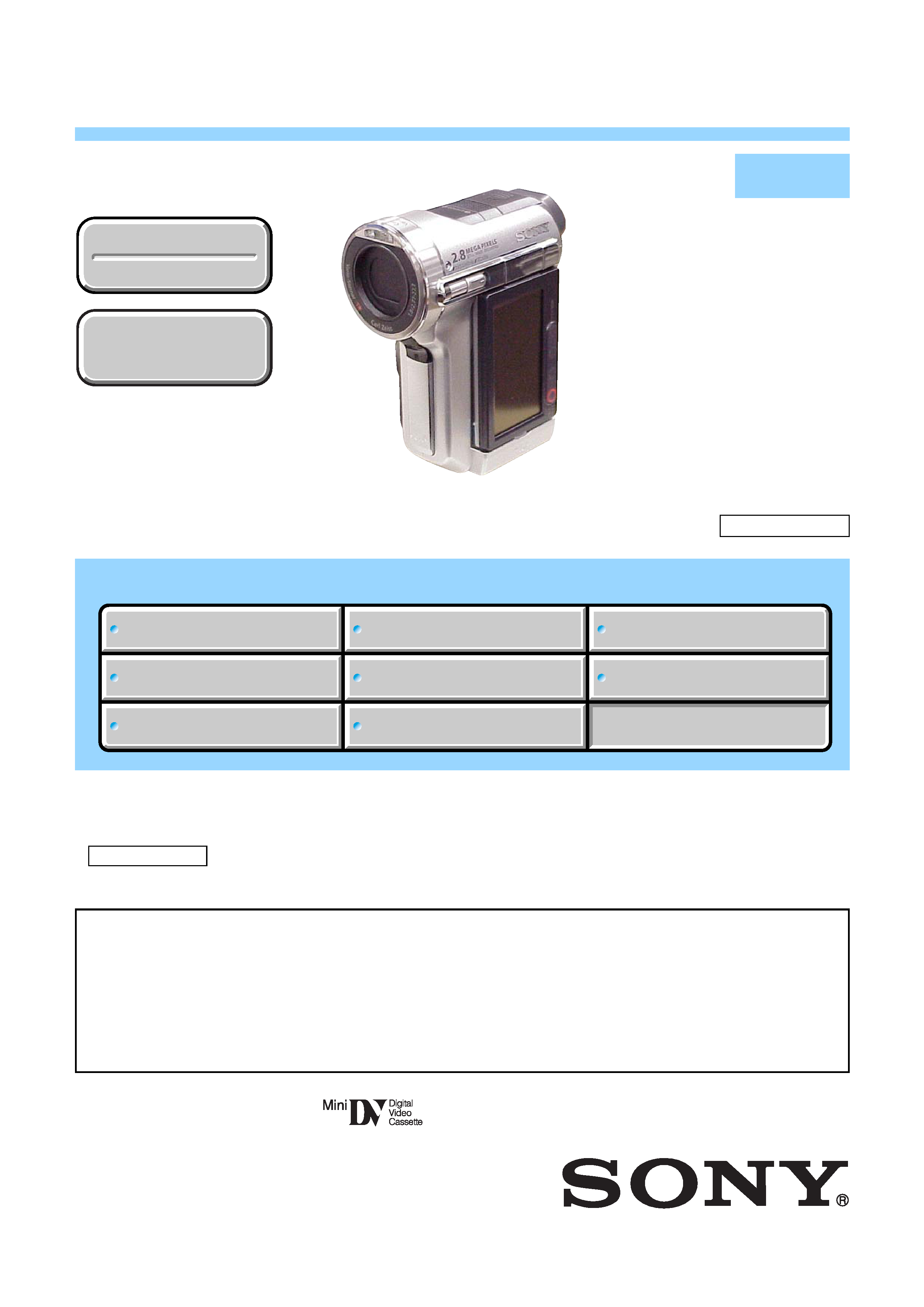
DCR-PC1000/PC1000E
E Model
Tourist Model
SERVICE MANUAL
DIGITAL VIDEO CAMERA RECORDER
LEVEL
2
· For ADJUSTMENTS (SECTION 6), refer to SERVICE MANUAL, ADJ (9-876-872-51).
· For INSTRUCTION MANUAL, refer to SERVICE MANUAL, LEVEL 1 (9-876-872-41). (EXCEPT J MODEL)
· For MECHANISM ADJUSTMENTS, refer to the "DV MECHANICAL ADJUSTMENT MANUAL IX
N MECHANISM " (EXCEPT J: 9-876-789-11) (J: 9-876-789-01).
· Reference number search on printed wiring boards is available.
· TO TAKE OUT A CASSETTE WHEN NOT EJECT (FORCE EJECT)
Link
SERVICE NOTE
DISASSEMBLY
BLOCK DIAGRAMS
FRAME SCHEMATIC DIAGRAMS
SCHEMATIC DIAGRAMS
PRINTED WIRING BOARDS
REPAIR PARTS LIST
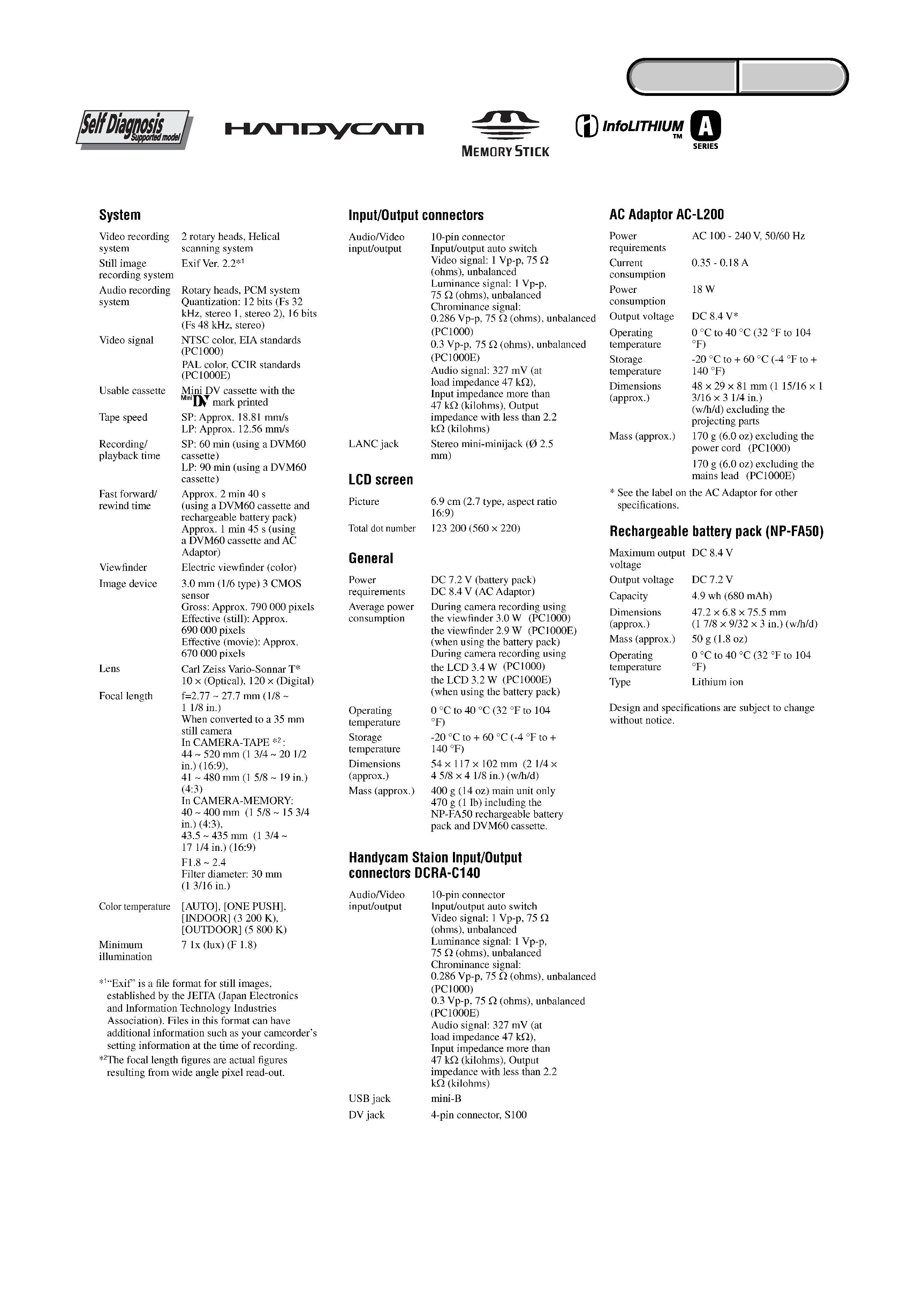
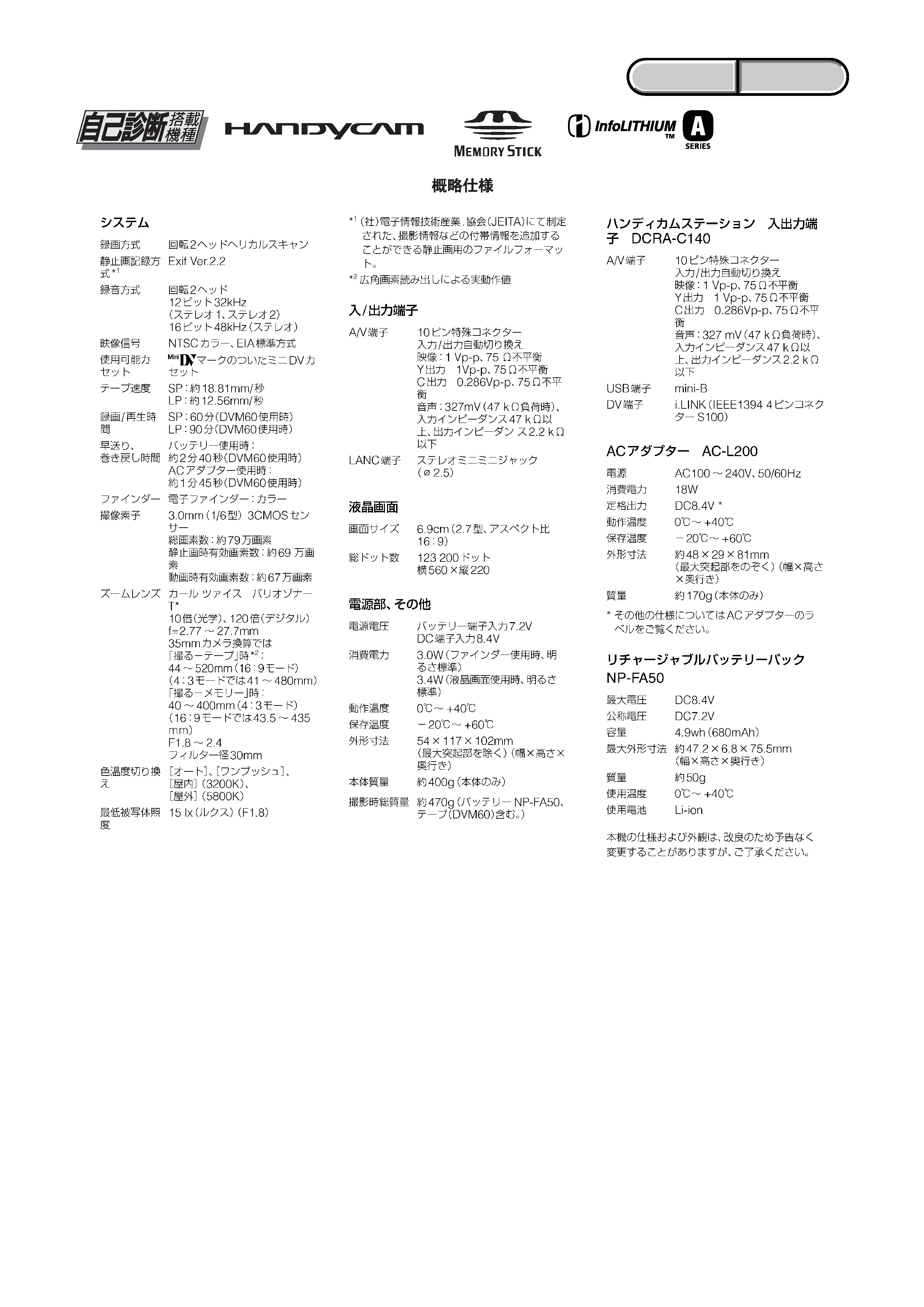
SPECIFICATIONS
SERVICE NOTE
DISASSEMBLY
BLOCK DIAGRAMS
FRAME SCHEMATIC DIAGRAMS
SCHEMATIC DIAGRAMS
PRINTED WIRING BOARDS
REPAIR PARTS LIST
SPECIFICATIONS
Link
Revision History
Revision History
Ver 1.3 2005. 11
On the VC-398 board
This service manual provides the information that is premised the circuit board replacement service and not intended repair
inside the VC-398 board.
Therefore, schematic diagram, printed wiring board, waveforms, mounted parts location and electrical parts list of the VC-398
board are not shown.
The following pages are not shown.
Mounted parts location ....................... Pages 4-100 to 4-101
Electrical parts list .............................. Pages 5-19 to 5-28
How to use
Acrobat Reader
How to use
Acrobat Reader
Schematic diagram ............................. Pages 4-31 to 4-76
Printed wiring board ............................ Pages 4-93 to 4-96
Waveforms ........................................... Pages 4-98
Sony EMCS Co.
2005K1600-1
©2005.11
Published by DI Technical Support Department
9-876-872-31
DCR-PC1000/PC1000E
RMT-831
N MECHANISM
DCR-PC1000/PC1000E
Photo : DCR-PC1000E
-- 2 --
DCR-PC1000/PC1000E
SPECIFICATIONS
ENGLISH
JAPANESE
ENGLISH
JAPANESE
-- 3 --
DCR-PC1000/PC1000E
ENGLISH
JAPANESE
ENGLISH
JAPANESE
-- 4 --
DCR-PC1000/PC1000E
ENGLISH
JAPANESE
ENGLISH
JAPANESE
1.
Check the area of your repair for unsoldered or poorly-soldered
connections. Check the entire board surface for solder splashes
and bridges.
2.
Check the interboard wiring to ensure that no wires are
"pinched" or contact high-wattage resistors.
3.
Look for unauthorized replacement parts, particularly
transistors, that were installed during a previous repair. Point
them out to the customer and recommend their replacement.
4.
Look for parts which, through functioning, show obvious signs
of deterioration. Point them out to the customer and
recommend their replacement.
5.
Check the B+ voltage to see it is at the values specified.
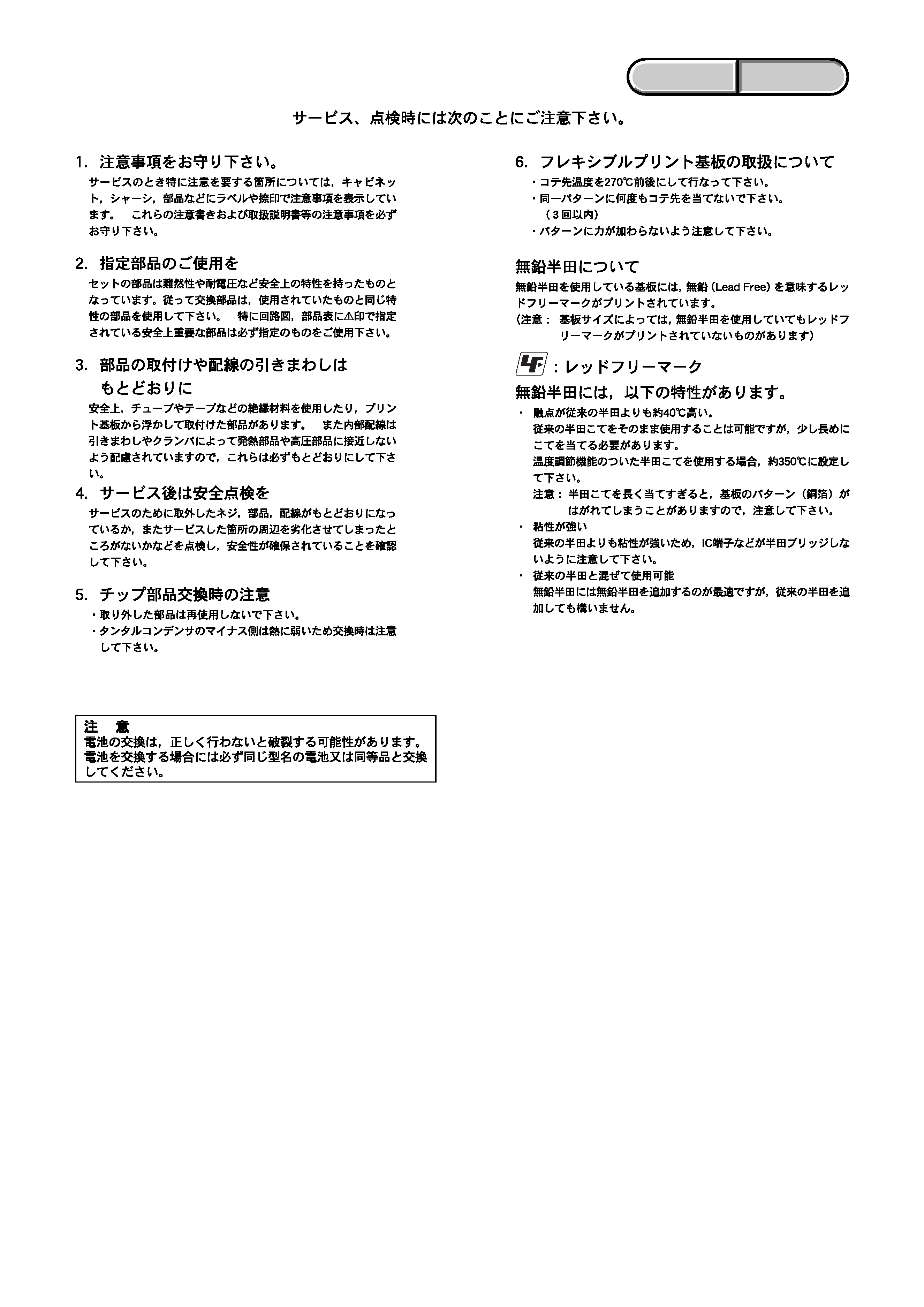
6.
Flexible Circuit Board Repairing
· Keep the temperature of the soldering iron around 270°C
during repairing.
· Do not touch the soldering iron on the same conductor of the
circuit board (within 3 times).
· Be careful not to apply force on the conductor when soldering
or unsoldering.
Unleaded solder
Boards requiring use of unleaded solder are printed with the lead-
free mark (LF) indicating the solder contains no lead.
(Caution: Some printed circuit boards may not come printed with
the lead free mark due to their particular size.)
: LEAD FREE MARK
Unleaded solder has the following characteristics.
· Unleaded solder melts at a temperature about 40
°C higher than
ordinary solder.
Ordinary soldering irons can be used but the iron tip has to be
applied to the solder joint for a slightly longer time.
Soldering irons using a temperature regulator should be set to
about 350
°C.
Caution: The printed pattern (copper foil) may peel away if the
heated tip is applied for too long, so be careful!
· Strong viscosity
Unleaded solder is more viscous (sticky, less prone to flow) than
ordinary solder so use caution not to let solder bridges occur such
as on IC pins, etc.
· Usable with ordinary solder
It is best to use only unleaded solder but unleaded solder may
also be added to ordinary solder.
SAFETY CHECK-OUT
After correcting the original service problem, perform the following
safety checks before releasing the set to the customer.
SAFETY-RELATED COMPONENT WARNING!!
COMPONENTS IDENTIFIED BY MARK 0 OR DOTTED LINE WITH
MARK 0 ON THE SCHEMATIC DIAGRAMS AND IN THE PARTS
LIST ARE CRITICAL TO SAFE OPERATION. REPLACE THESE
COMPONENTS WITH SONY PARTS WHOSE PART NUMBERS
APPEAR AS SHOWN IN THIS MANUAL OR IN SUPPLEMENTS
PUBLISHED BY SONY.
ATTENTION AU COMPOSANT AYANT RAPPORT
À LA SÉCURITÉ!
LES COMPOSANTS IDENTIFÉS PAR UNE MARQUE 0 SUR LES
DIAGRAMMES SCHÉMATIQUES ET LA LISTE DES PIÈCES SONT
CRITIQUES POUR LA SÉCURITÉ DE FONCTIONNEMENT. NE
REMPLACER CES COMPOSANTS QUE PAR DES PIÈSES SONY
DONT LES NUMÉROS SONT DONNÉS DANS CE MANUEL OU
DANS LES SUPPÉMENTS PUBLIÉS PAR SONY.
CAUTION :
Danger of explosion if battery is incorrectly replaced.
Replace only with the same or equivalent type.
-- 5 --
DCR-PC1000/PC1000E
ENGLISH
JAPANESE
ENGLISH
JAPANESE