SERVICE MANUAL
MICROFILM
DCR-PC100/PC100E
RMT-811
US Model
Canadian Model
Korea Model
DCR-PC100
AEP Model
UK Model
Australian Model
Chinese Model
DCR-PC100E
E Model
Hong Kong Model
Tourist Model
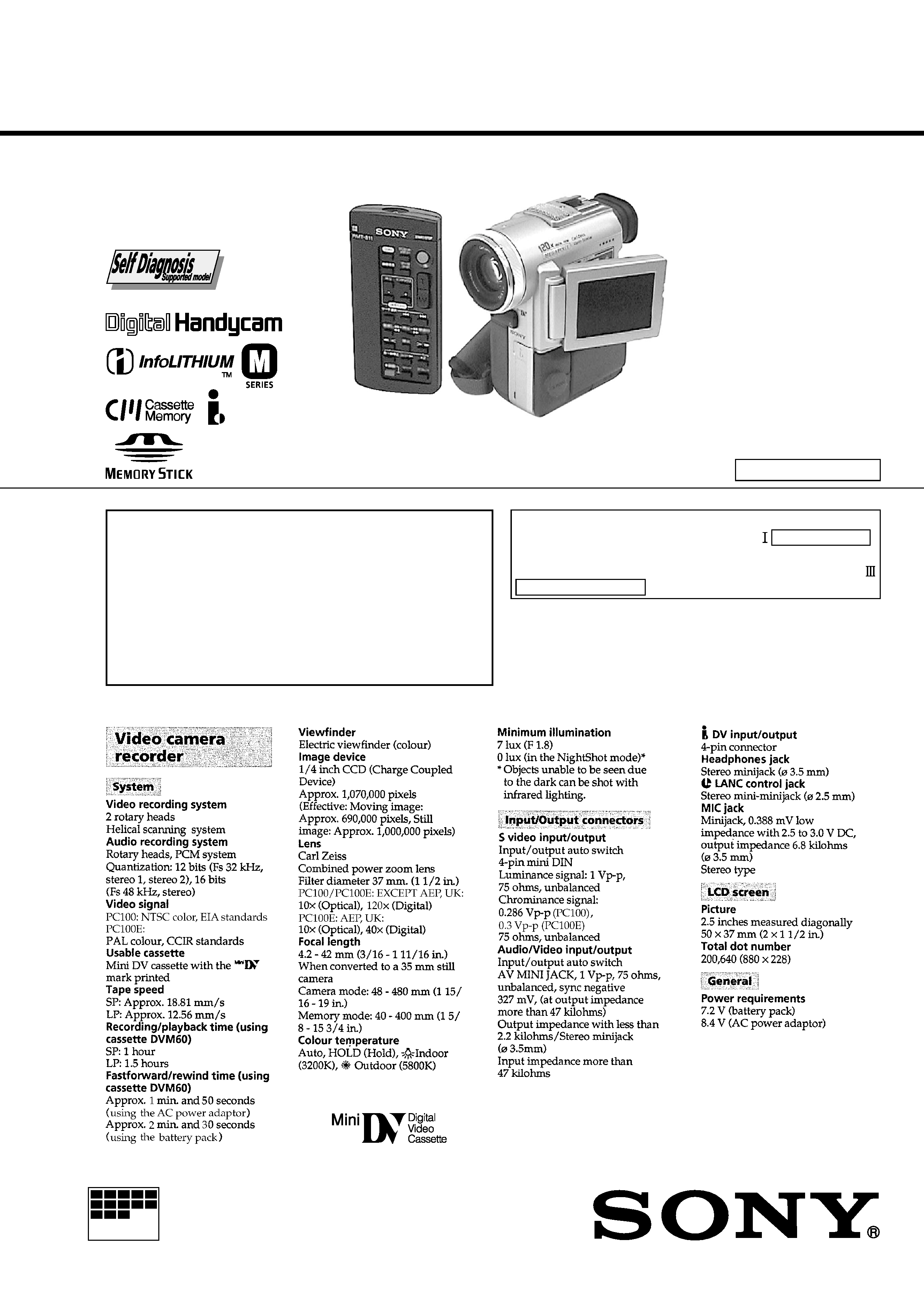
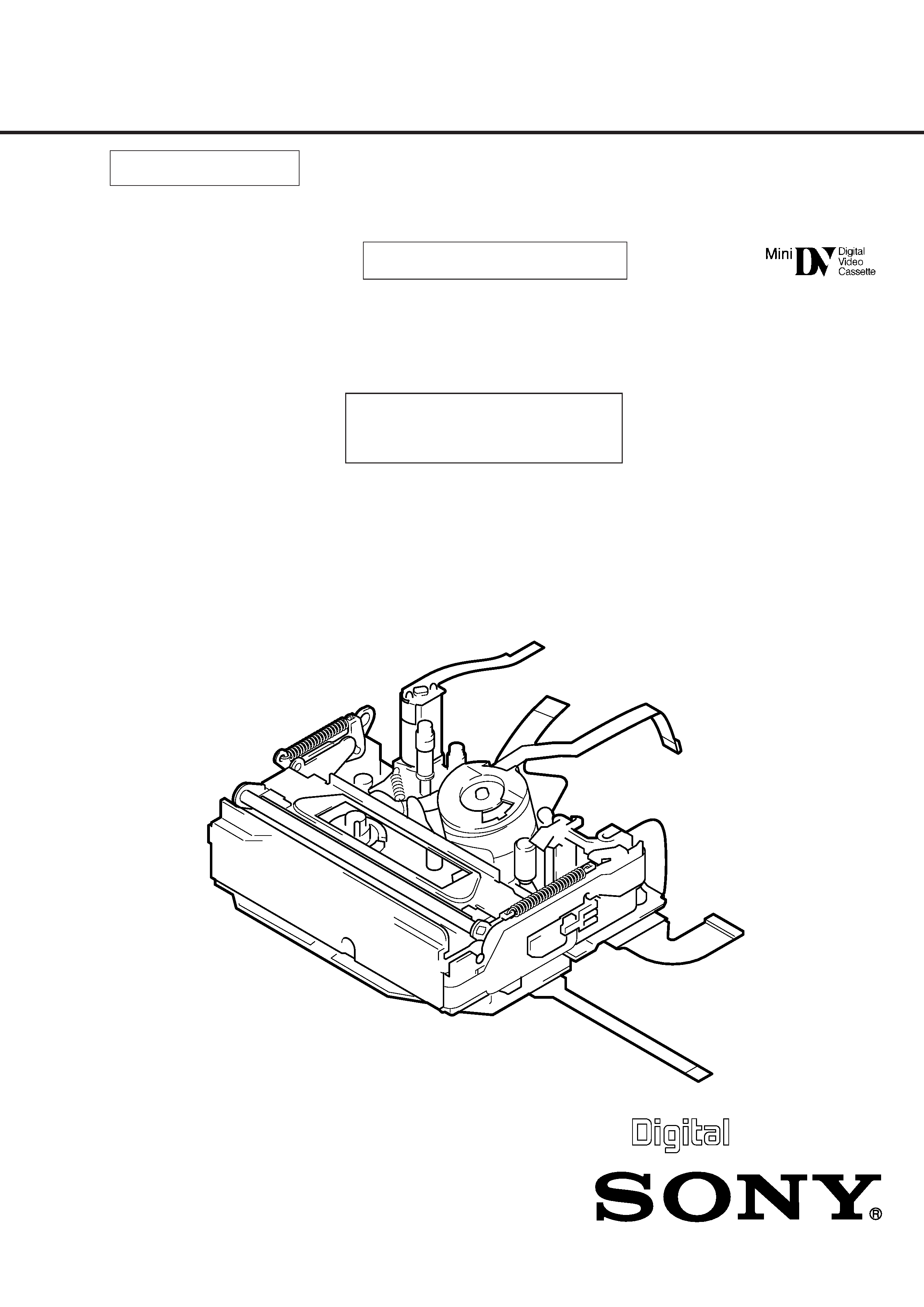
DCR-PC100/PC100E
SERVICE MANUAL
DIGITAL VIDEO CAMERA RECORDER
D300 MECHANISM
Photo : DCR-PC100
SPECIFICATIONS
DCR-PC100
: NTSC model
DCR-PC100E : PAL model
For MECHANISM ADJUSTMENTS, refer to the "DV
MECHANICAL ADJUSTMENT MANUAL
D MECHANISM"
(original: 9-973-815-11, supplement: 9-973-815-81)
and "DV MECHANICAL ADJUSTMENT MANUAL
D200 MECHANISM " (original: 9-973-981-11).
-- Continued on next page --
On the VC-227 board
This service manual provides the information that is premised
the circuit board replacement service and not intended repair
inside the VC-227 board.
Therefore, schematic diagram, printed wiring board and
electriacal parts list of the VC-227 board are not shown.
The following pages are not shown.
Schematic diagram .......................... Pages 4-13 to 4-42
Printed wiring board ......................... Pages 4-43 to 4-46
Electrical parts list ............................ Pages 6-18 to 6-25
Ver 1.2 2001. 12
-- 1 --
DV MECHANICAL ADJUSTMENT MANUAL
III
Only differences compared with the "DV MECHANICAL ADJUSTMENT MANUAL I
(D MECHANISM)" are mentioned in this service manual. Use with service manual
(Original : 9-973-815-11, CORRECTION-1 : 9-973-815-92) for repair.
MAIN DIFFERENCES
1. Cassette compartment's form
2. Attachment of LM motor
3. Change of the EJ arm's form
Note : The page No. ( ) stated on top of each title shows you the page No. in the pre-
vious issued original service manual, "CORRECTION-1"or "DV MECHANICAL
ADJUSTMENT MANUAL I" .
Example : (Original
: Page 6)
(Correction-1 : Page 2)
2-4. SERVICE JIGS LIST
MECHANISM
D200 MECHANISM
Difference Manual

_2_
TABLE OF CONTENTS
Note : Regarding to sections not mentioned in followings, refer to the
original manual (D mechanism). Some reference pages among
them are to be referred to this "Difference Manual".
Section
Title
Page
1.
PREPARATION FOR MECHANICAL CHECK,
ADJUSTMENT AND MAINTENANCE
1-1.
Cassette Compartment Assembly ........................................ 3
2.
PERIODIC CHECK AND MAINTENANCE
2-4.
Service Jigs List ................................................................... 4
2-5.
Use of Mode Selector II .............................................................. 6
2-5-1.
Outline ......................................................................... 6
3.
MECHANISM SECTION CHECKS, ADJUSTMENTS
AND REPRACEMENTS
3-1.
Drum Assembly
(Motor FPC Assembly, Elastic Connectors) .......................... 7
3-8.
LM Motor Assembly .............................................................. 8
3-13. T Hard Brake, L Brake, S Brake Arm, S Hard
and CC Switch Cover ............................................................. 9
3-17. FWD BackTension Adjustment ............................................... 10
3-18. Reel Table Torque Check ...................................................... 10
3-22. LS Chassis Block Assembly, Gooseneck Assembly,
Relay Gear, Cam Slider, Comulsion Arm Assembly ................. 11
3-25. Mode Cam Assembly, FP-585 Flexible Board ..................... 12
3-26. LS Arm Assembly, Eject Lever,
Cam (S) Spacer and Cam (S) Assembly ............................ 13
5.
EXPLODED VIEW
5-1.
Cassette Compartment and Drum assembly ...................... 14
5-2.
LS Chassis Assembly ......................................................... 15
5-3.
Mechanism Chassis Assembly (1) ..................................... 16
5-4.
Mechanism Chassis Assembly (2) ..................................... 17
6.
PRINTED WIRING BOARD AND
SCHEMATIC DIAGRAM ................................................ 18
7.
ELECTRICAL PARTS LIST .......................................... 19
_3_
PREPARATION
· For removal of the cabinet and boards, refer to "Disassembly" in
each service manual.
· When the adjustment and maintenance for the mechanical section
are performed, select the condition of mechanical deck using mode
selector II for easy use to operate. Refer to "2-5. How to handle
the mode selector II" to select the following each
mode.
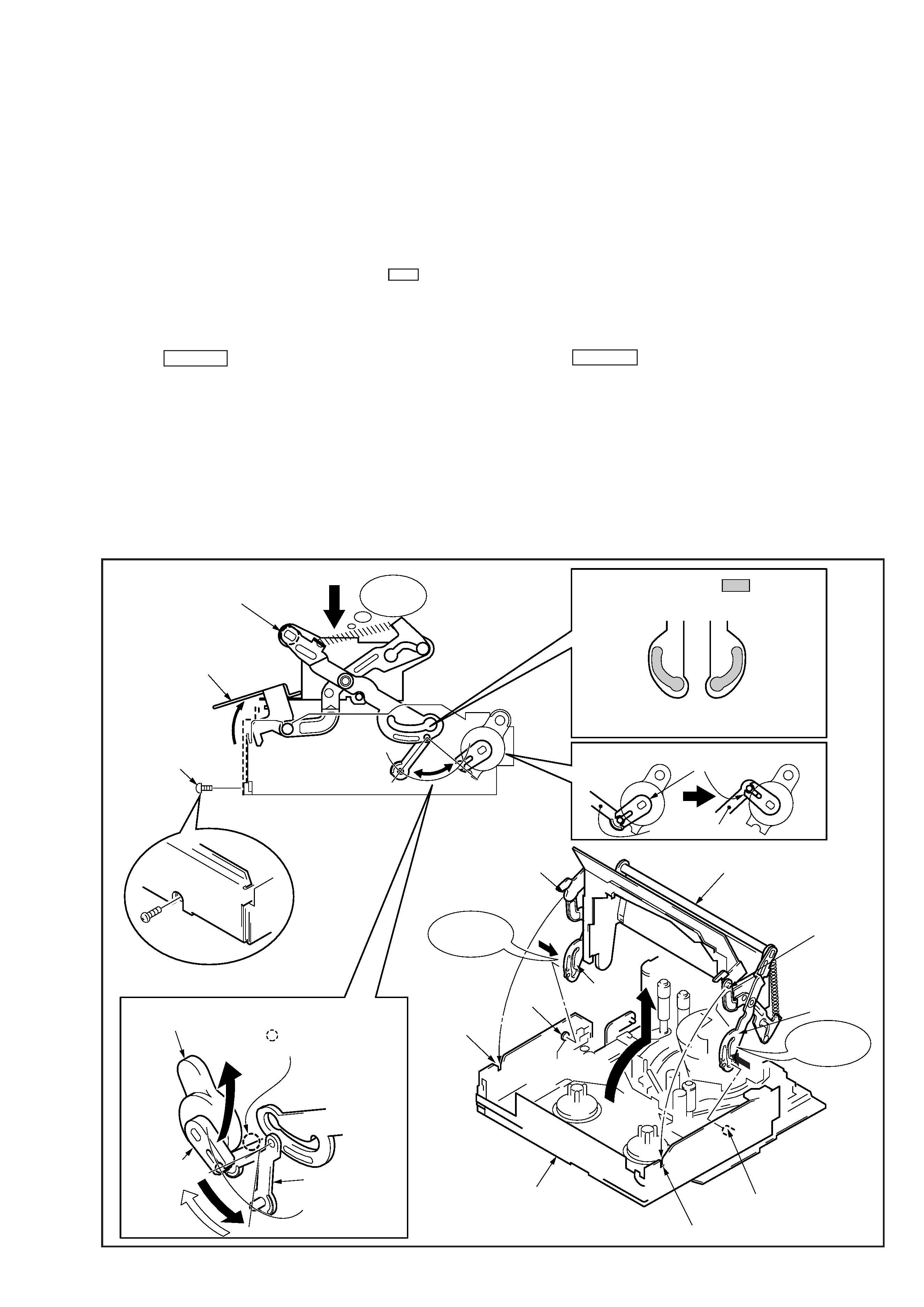
1-1. CASSETTE COMPARTMENT ASSEMBLY
1. Removing
1) Set the USE--EJ mode.
2) Remove the damper joint plate from the damper. (See figure. I)
3) Remove the screw.
4) Push down the joint shaft, and move the LS frame to the direction
of arrow B.
5) Lift the cassette compartment assembly to the direction of arrow
C, then remove pressing the left and right holder arms to inside.
2-1. PREPARATION FOR MECHANICAL CHECK,ADJUSTMENT AND MAINTENANCE
2. Attaching
1) Set the USE--EJ mode.
2) Apply the grease (two positions, 1.5 mm dia.) to the holder arm,
then attach it to the shaft C pressing the holder arms to inside.
Grease: Floil Grease (SG-941)(See figure.II)
3) Attach the damper joint plate to the damper in the direction of
arrowA
.
4) Push up the damper arm in the direction of arrow D.
5) Pull down the cassette compartment assembly to front, attach the
shaft D to a groove of LS chassis, then pull down the LS frame to
front.
6) Attach the screw.
Fixing torque: 0.0588 N · m (0.6 kg · cm)
(Original : Page 3)
LS chassis
Apply the grease to
parts
when attaching.
Holder arm (inside of holes.)
Special head screw
(M1.4 x 1.6)
B
LS frame
Joint shaft
Push down.
LS chassis
Cassette compartment
assembly
Damper arm
Damper arm
Damper joint plate
Shaft D
Holder arm
Shaft C
Groove
Pressing to
inside.
Pressing to
inside.
Groove
Damper
Damper joint plate
Push the
section in the direction
of arrow A
b.
Shaft C
Holder arm
Shaft D
A
A
C
Fig.II
Fig.III
Fig.I
D
NG
OK

_4_
Other equipment used
· Oscilloscope
Note 1: If the micro processor IC in the adjusting remote
commander is not the new micro processor (UPD7503G-
C56-12), the pages cannot be switched.
In this case, replase with the new micro processor
(8-759-148-35).
Usage, Others Application, etc
Tape path
Tape path
For FWD torque, RVS torque and FWD
back tension.
For adjusting tape guide
For all operating
For adjusting FWD position and FWD
back tension
Name
Cleaning fluid
Wiping cloth
Super fine applicator
(Made by NIPPON APPLICATOR (P752D))
Mirror (Small oval type)
Tracking tape (XH2-1) (NTSC/PAL)
Mini DV torque cassette
Cassette standerd plate
Reel standard plate
Dummy drum (D mechnism)
TG1 preset base (D mechanism)
TG5 preset base (D mechanism)
Washer fixture ø0.8
Torque driver
Screwdriver for tape path
Adjusting remote commander
(RM-95 remodeled partly) Note1
Mode selector II
Mode selector II change connctor board
Screw lock G (1401B)
FWD/BACK Tension adjustment driver
Ref. No.
J-1
J-2
J-3
J-4
J-5
J-6
J-7
J-8
J-9
J-10
J-11
J-12
J-13
J-14
J-15
J-16
J-17
J-18
J-19
Part No.
Y-2031-001-0
7-741-900-53
J-6080-840-A
8-967-997-01
J-6082-360-A
J-6082-330-A
J-6082-331-A
J-6082-332-A
J-6082-333-A
J-6082-334-A
J-6082-233-A
J-9049-330-A
J-6082-026-A
J-6082-053-B
J-6082-282-A
J-6082-335-A
7-432-114-11
J-6082-187-A
Fixtur No.
GD-2038
2-4. SERVICE JIGS LIST
(Original
: Page 6)
(Correction-1 : Page 2)