SERVICE MANUAL
· INSTRUCTION MANUAL is shown at the end of this document.
· Table for differences of function of each model.
Revision History
Revision History
Ver 1.0 2002. 09
LEVEL
1
Link
SELF DIAGNOSIS FUNCTION
ORNAMENTAL PARTS
SPECIFICATIONS
SELF DIAGNOSIS FUNCTION
ORNAMENTAL PARTS
SPECIFICATIONS
Link
V MECHANISM
DCR-IP210/IP210E/
IP220/IP220E
RMT-817
US Model
Canadian Model
DCR-IP220
AEP Model
UK Model
Australian Model
DCR-IP220E
East European Model
DCR-IP210E/IP220E
Tourist Model
DCR-IP210/IP210E
E Model
DCR-IP210/IP210E/IP220/IP220E
Chinese Model
DCR-IP210E
Korea Model
DCR-IP210
Hong Kong Model
DCR-IP210/IP220E
DIGITAL VIDEO CAMERA RECORDER
Photo : DCR-IP220E

-- 2 --
DCR-IP210/IP210E/IP220/IP220E
SPECIFICATIONS
SAFETY-RELATED COMPONENT WARNING!!
COMPONENTS IDENTIFIED BY MARK 0 OR DOTTED LINE WITH
MARK 0 ON THE SCHEMATIC DIAGRAMS AND IN THE PARTS
LIST ARE CRITICAL TO SAFE OPERATION. REPLACE THESE
COMPONENTS WITH SONY PARTS WHOSE PART NUMBERS
APPEAR AS SHOWN IN THIS MANUAL OR IN SUPPLEMENTS
PUBLISHED BY SONY.
ATTENTION AU COMPOSANT AYANT RAPPORT
À LA SÉCURITÉ!
LES COMPOSANTS IDENTIFÉS PAR UNE MARQUE 0 SUR LES
DIAGRAMMES SCHÉMATIQUES ET LA LISTE DES PIÈCES SONT
CRITIQUES POUR LA SÉCURITÉ DE FONCTIONNEMENT. NE
REMPLACER CES COMPOSANTS QUE PAR DES PIÈSES SONY
DONT LES NUMÉROS SONT DONNÉS DANS CE MANUEL OU
DANS LES SUPPÉMENTS PUBLIÉS PAR SONY.
COVER
COVER
CAUTION :
Danger of explosion if battery is incorrectly replaced.
Replace only with the same or equivalent type.
Video camera
recorder
System
Video recording system
2 rotary heads
Helical scanning system
Audio recording system
MPEG1 Audio Layer2
(Fs 48 kHz, stereo)
Video signal
DCR-IP210/IP220:
NTSC color, EIA standards
DCR-IP210E/IP220E:
PAL colour, CCIR standards
Usable cassette
MICROMV cassette with the
mark printed
Tape speed
Approx. 5.66 mm/s
Recording/playback time
(using cassette MGR60)
1 hour
Fastforward/rewind time
(using cassette MGR60)
Approx. 1 min. and 30 seconds
Viewfinder
Electric viewfinder (colour)
Image device
5.0 mm (1/3.6 type) CCD
(Charge Coupled Device)
Gross: Approx. 2 110 000 pixels
Effective (still):
Approx. 1 920 000 pixels
Effective (moving):
Approx. 1 080 000 pixels
Lens
Carl Zeiss Vario-Sonnar T*
Combined power zoom lens
Filter diameter 37 mm (1 13/16 in.)
10
× (Optical), 120× (Digital)
Focal length
4.5 45 mm (3/16 1 13/16 in.)
When converted to a 35 mm still
camera
CAMERA:
52 520 mm (2 1/8 20 1/2 in.)
MEMORY:
39 390 mm (1 11/16 16 5/8 in.)
Colour temperature
AUTO, HOLD, INDOOR
(3 200K), OUTDOOR (5 800K)
Minimum illumination
7 lx (lux) (F 1.8)
0 lx (lux) (in the NightShot mode)*
* Objects unable to be seen due to
the dark can be shot with infrared
lighting.
Input/Output connectors
Audio/Video input/output
10-pin connector
Input/output auto switch
Video signal: 1 Vp-p, 75
(ohms),
unbalanced, sync negative
Luminance signal: 1 Vp-p, 75
(ohms), unbalanced
Chrominance signal:
DCR-IP210/IP220: 0.286 Vp-p,
DCR-IP210E/IP220E: 0.3 Vp-p,
75
(ohms), unbalanced
Audio signal: 327 mV, (at output
impedance more than 47 k
(kilohms))
Input impedance with more than
47 k
(kilohms)
Output impedance with less than
2.2 k
(kilohms)
i.LINK (MICROMV Interface)
input/output
4-pin connector S400
LANC jack
Stereo mini-minijack (ø 2.5 mm)
USB jack
mini-B
Headphone jack
Stereo minijack (ø 3.5 mm)
LCD screen
Picture
6.2 cm (2.5 type)
Total dot number
211 200 (960
× 220)
Wireless communication
(DCR-IP220/IP220E only)
Communication system
Bluetooth specification Ver.1.1
Maximum communication
speed1) 2)
Approx. 723 kbps
Maximum output
Bluetooth specification Power
Class2
Communication distance2)
Approx. 10 m (33 feet) (Open space,
when using a Sony BTA-NW1/
NW1A Modem Adaptor with
Bluetooth Function)
Compatible Bluetooth profiles3)
Generic Access Profile
Dial-up Networking Profile
Usable frequency band
2.4 GHz band
(2.400 2.483 5 GHz)
1) The maximum rate defined by
Bluetooth specification Ver.1.1
2) Depends on obstacles between the
Bluetooth devices, radio wave
conditions, etc.
3) Defined by Bluetooth
specification for intended use
between the Bluetooth devices
General
Power requirements
7.2 V (battery pack)
8.4 V (AC power adaptor)
Average power consumption
(when using the battery pack)
During camera recording using
LCD: 4.8 W
Viewfinder: 4.2 W
Operating temperature
0
°C to 40°C (32°F to 104°F)
Storage temperature
20
°C to +60°C (4°F to +140°F)
Dimensions (approx.)
98
× 75.5 × 136 mm
(3 7/8
× 3 × 5 3/8 in.) (w/h/d)
Mass (approx.)
520 g (1 lb 2 oz)
excluding the battery pack and
cassette
630 g (1 lb 6 oz)
including the battery pack,
NP-FF70, cassette MGR60, lens cap
and stylus
Supplied accessories
See page 3.
AC power adaptor
Power requirements
100 240 V AC, 50/60 Hz
Power consumption
23 W
Output voltage
DC OUT: 8.4 V, 1.5 A in the
operating mode
Operating temperature
0
°C to 40°C (32°F to 104°F)
Storage temperature
20
°C to +60°C (4°F to +140°F)
Dimensions (approx.)
125
× 39 × 62 mm (5 × 1 9/16 × 2 1/2
in.) (w/h/d) excluding projecting
parts
Mass (approx.)
280 g (9.8 oz)
excluding mains lead
Battery pack
Maximum output voltage
DC 8.4 V
Output voltage
DC 7.2 V
Capacity
9.6 Wh (1 350 mAh)
Operating temperature
0
°C to 40°C (32°F to 104°F)
Dimensions (approx.)
40.8
× 24.1 × 49.1 mm
(1 5/8
× 31/32 × 1 15/16 in.)
(w/h/d)
Mass (approx.)
90 g (3.2 oz)
Type
Lithium ion
"Memory Stick"
Memory
Flash memory
8MB: MSA-8A
Operating voltage
2.7 3.6 V
Power consumption
Approx. 45 mA in the operating
mode
Approx. 130
µA in the standby
mode
Dimensions (approx.)
50
× 2.8 × 21.5 mm
(2
× 1/8 × 7/8 in.) (w/h/d)
Mass (approx.)
4 g (0.14 oz)
Design and specifications are
subject to change without notice.
-- 3 --
DCR-IP210/IP210E/IP220/IP220E
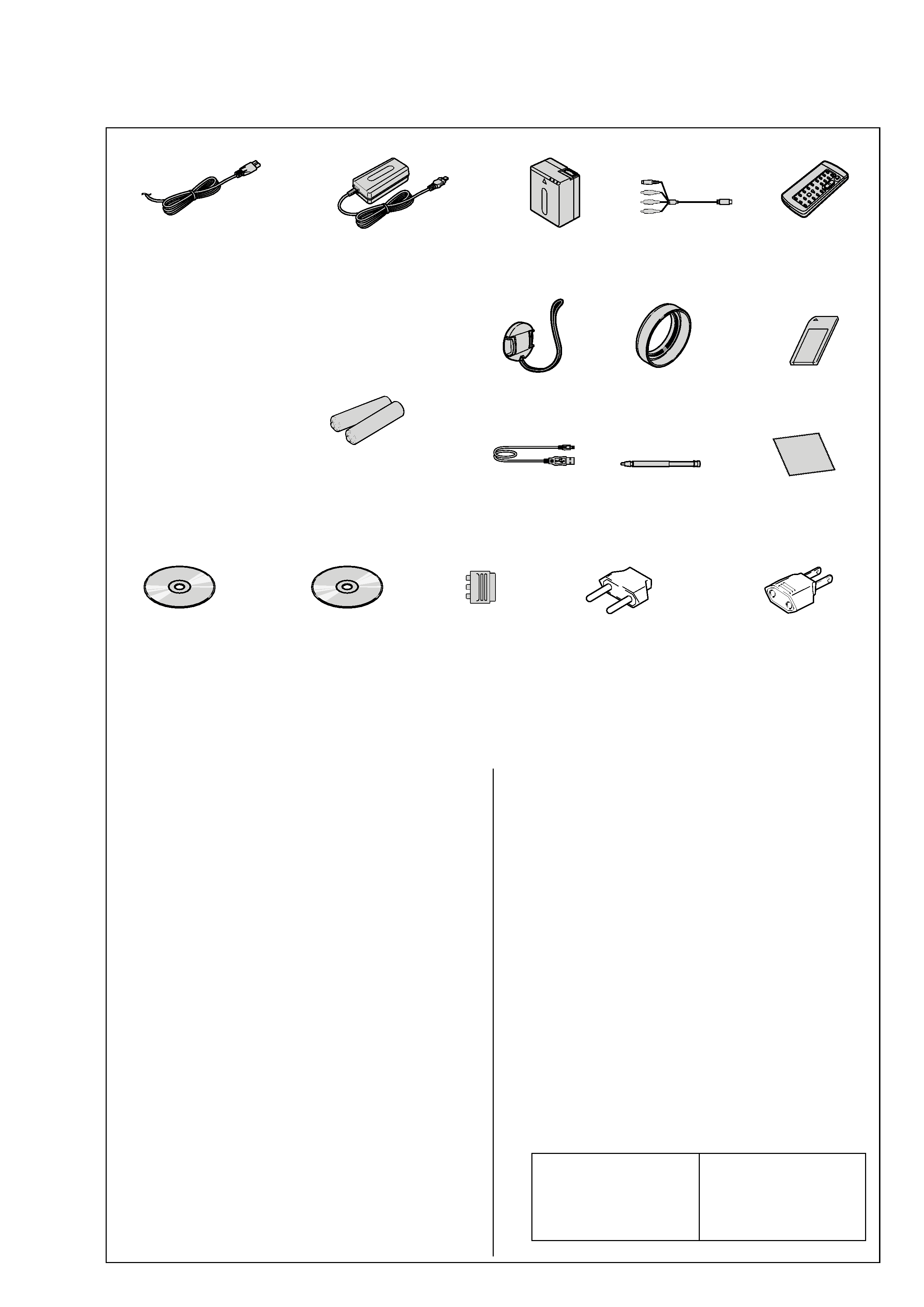
Checking supplied accessories.
Other accessories
3-053-056-01 LID, BATTERY CASE (FOR RMT-817)
3-070-303-11 OPERATING, INSTRUCTION(PC APPLI)(ENGLISH)
(IP210:E,HK,JE/IP210E:E,CH,JE/IP220/IP220E:AEP,UK,EE,E)
3-070-303-21 OPERATING, INSTRUCTION(PC APPLI)(FRENCH/GERMAN)
(IP210E:E,JE/IP220:CND/IP220E:AEP, E)
3-070-303-31 OPERATING, INSTRUCTION (PC APPLI)
(SPANISH/PORTUGUESE)(IP210:E,JE/IP220:E/IP220E:AEP)
3-070-303-41 OPERATING, INSTRUCTION(RUSSIAN/DUTCH)
(IP210E:E/IP220E:AEP,E)
3-070-303-51 OPERATING, INSTRUCTION(ITALIAN/GREEK)(IP220E:AEP)
3-070-303-61 OPERATING, INSTRUCTION(ARABIC/PERSIAN)
(IP210:E/IP210E:E/IP220:E/IP220E:E)
3-070-303-71 OPERATING, INSTRUCTION (TRADITIONAL CHINESE)
(IP210:E,HK/IP220:E/IP220E:HK)
3-076-897-11 MANUAL, INSTRUCTION(SET)(ENGLISH)
(IP210:E,HK,JE/IP220)
3-076-897-21 MANUAL, INSTRUCTION(SET)(FRENCH)(IP220:CND)
3-076-897-31 MANUAL, INSTRUCTION(SET)(SPANISH/PORTUGUESE)
(IP210:E,JE/IP220:E)
3-076-897-41 MANUAL, INSTRUCTION(SET)(TRADITIONAL CHINESE)
(IP210:E,HK/IP220:E)
3-076-897-51 MANUAL, INSTRUCTION(SET)(ARABIC)(IP210:E/IP220:E)
3-076-897-61 MANUAL, INSTRUCTION(SET)(KOREAN)(IP210:JE,KR)
3-076-898-11 MANUAL, INSTRUCTION(SET)(ENGLISH/RUSSIAN)
(IP210E:E,CH,JE/IP220E:UK,E,HK)
3-076-898-21 MANUAL, INSTRUCTION(SET)(FRANCH/GERMAN)
(IP210E:E,JE/IP220E:AEP,E)
3-076-898-31 MANUAL, INSTRUCTION(SET)(ENGLISH/DUTCH)
(IP220E:AEP)
3-076-898-41 MANUAL, INSTRUCTION(SET)(SPANISH/PORTUGUESE)
(IP220E:AEP)
Make sure that the following accessories are supplied with your camcorder.
Power cord (Main lead)(1)
(AUS model)
0 1-696-819-11
Power cord (Main lead)(1)
(AEP, E, EE model)
0 1-769-608-11
Power cord (Main lead)(1)
(CH model)
0 1-782-476-11
Power cord (Main lead)(1)
(UK, HK model)
0 1-783-374-11
Power cord (Main lead)(1)
(US, CND model)
0 1-790-107-22
Power cord (Main lead)(1)
(JE model)
0 1-790-732-11
Power cord (Main lead)(1)
(KR model)
0 1-823-947-11
AC power adaptor (1) (AC-L20A)
(US, CND, AEP, UK, E, HK, AUS, EE, JE
model)
0 1-476-779-12
AC power adaptor (1) (AC-L20A)
(KR model)
0 1-476-779-22
AC power adaptor (1) (AC-L20A)
(CH model)
0 1-476-779-32
R6 (size AA) batteries
for the Remote
Commander (2)
(not supplied)
21-pin adaptor (1)
(AEP, UK, EE model)
1-770-783-21
Lens cap (1)
X-3952-743-1
A/V connecting cable
(1.5m) (1)
1-823-156-12
NP-FF70 batter y
pack (1)
(not supplied)
Cleaning cloth (1)
3-073-861-01
Wireless Remote
Commander (1)
(RMT-817)
1-477-641-21
"Memory Stick" (1)
(MSA-8A)
A-7024-735-A
USB cable (1)
1-823-931-11
CD-ROM
(SPVD-008 USB Driver) (1)
(AEP, UK, EE, E, HK, AUS,
JE, KR, CH model)
3-077-023-02
CD-ROM
(SPVD-008(I) USB Driver) (1)
(US,CND model)
3-077-012-02
CD-ROM
(MovieShaker Ver.3.1
for MICROMV) (1)
3-070-810-01
Stylus (1)
(DCR-IP220/IP220E
only)
3-073-941-01
2-pin conversion adaptor (1)
(IP210:JE/IP210E:JE only)
1-569-007-11
2-pin conversion adaptor (1)
(IP210:E,HK/IP210E:E/
IP220:E/IP220E:E,HK only)
1-569-008-21
3-076-898-51 MANUAL, INSTRUCTION(SET)(ITALIAN/GREEK)
(IP220E:AEP)
3-076-898-61 MANUAL, INSTRUCTION(SET)(ARABIC/PERSIAN)
(IP210E:E/IP220E:E)
3-076-898-71 MANUAL, INSTRUCTION(SET)(TRADITIONAL CHINESE)
(IP220E:HK)
3-076-898-81 MANUAL, INSTRUCTION(SET)(SIMPLIFIED CHINESE)
(IP210E:E,CH,JE/IP220E:E)
3-078-153-11 MANUAL, INSTRUCTION(NETWORK)(ENGLISH)
(IP220:US)
3-078-154-11 MANUAL, INSTRUCTION(NETWORK)(ENGLISH/FRENCH)
(IP220:CND,E/IP220E:E,HK)
3-078-154-21 MANUAL, INSTRUCTION(NETWORK)(ENGLISH/DUTCH)
(IP220E:AEP,UK)
3-078-154-31 MANUAL, INSTRUCTION(NETWORK)(FRENCH/GERMAN)
(IP220E:AEP)
3-078-154-41 MANUAL, INSTRUCTION(NETWORK)(ITALIAN/GREEK)
(IP220E:AEP)
3-078-154-51 MANUAL, INSTRUCTION(NETWORK)
(SPANISH/PORTUGUESE)(IP220E:AEP)
3-078-154-61 MANUAL, INSTRUCTION(NETWORK)
(TRADITIONAL CHINESE)(IP220:E/IP220E:HK)
3-078-154-71 MANUAL, INSTRUCTION(NETWORK)
(SIMPLIFIED CHINESE)(IP220E:E)
Note :
The components identified by
mark 0 or dotted line with mark
0 are critical for safety.
Replace only with part number
specified.
Note :
Les composants identifiés par
une marque 0 sont critiques
pour la sécurité.
Ne les remplacer que par une
pièce portant le numéro spécifié.
Lens hood (1)
3-077-501-01
· Abbreviation
CND : Canadian model
EE
: East European model
HK
: Hong Kong model
AUS : Australian model
CH
: Chinese model
JE
: Tourist model
KR
: Korea model

-- 4 --
1.
Check the area of your repair for unsoldered or poorly-soldered
connections. Check the entire board surface for solder splashes
and bridges.
2.
Check the interboard wiring to ensure that no wires are
"pinched" or contact high-wattage resistors.
3.
Look for unauthorized replacement parts, particularly
transistors, that were installed during a previous repair. Point
them out to the customer and recommend their replacement.
4.
Look for parts which, through functioning, show obvious signs
of deterioration. Point them out to the customer and
recommend their replacement.
5.
Check the B+ voltage to see it is at the values specified.
6.
Flexible Circuit Board Repairing
· Keep the temperature of the soldering iron around 270°C
during repairing.
· Do not touch the soldering iron on the same conductor of the
circuit board (within 3 times).
· Be careful not to apply force on the conductor when soldering
or unsoldering.
SAFETY CHECK-OUT
After correcting the original service problem, perform the following
safety checks before releasing the set to the customer.
DCR-IP210/IP210E/IP220/IP220E
DCR-IP210
E/HK/KR/JE
NTSC
DCR-IP210E
EE/E/JE/CH
PAL
16Mbit
DCR-IP220E
AEP/UK/EE/
E/AUS/HK
PAL
· Abbreviation
CND : Canadian model
EE
: East European model
HK
: Hong Kong model
AUS : Australian model
JE
: Tourist model
CH
: Chinese model
KR
: Korea model
Table for difference of function
Model
Destination
Color System
NETWORK
(Bluetooth)
BT-012, AN-025 boards
Flash memory
(VC-308 board IC-904)
DCR-IP220
US/CND/E
NTSC
Remark
With BT-012,
AN-025 boards
a
a
64Mbit
-- 5 --
DCR-IP210/IP210E/IP220/IP220E
1.
SELF-DIAGNOSIS FUNCTION
When problems occur while the unit is operating, the self-diagnosis
function starts working, and displays on the viewfinder, or LCD
screen what to do. This function consists of two display; self-
diagnosis display and service mode display.
Details of the self-diagnosis functions are provided in the Instruction
manual.
2.
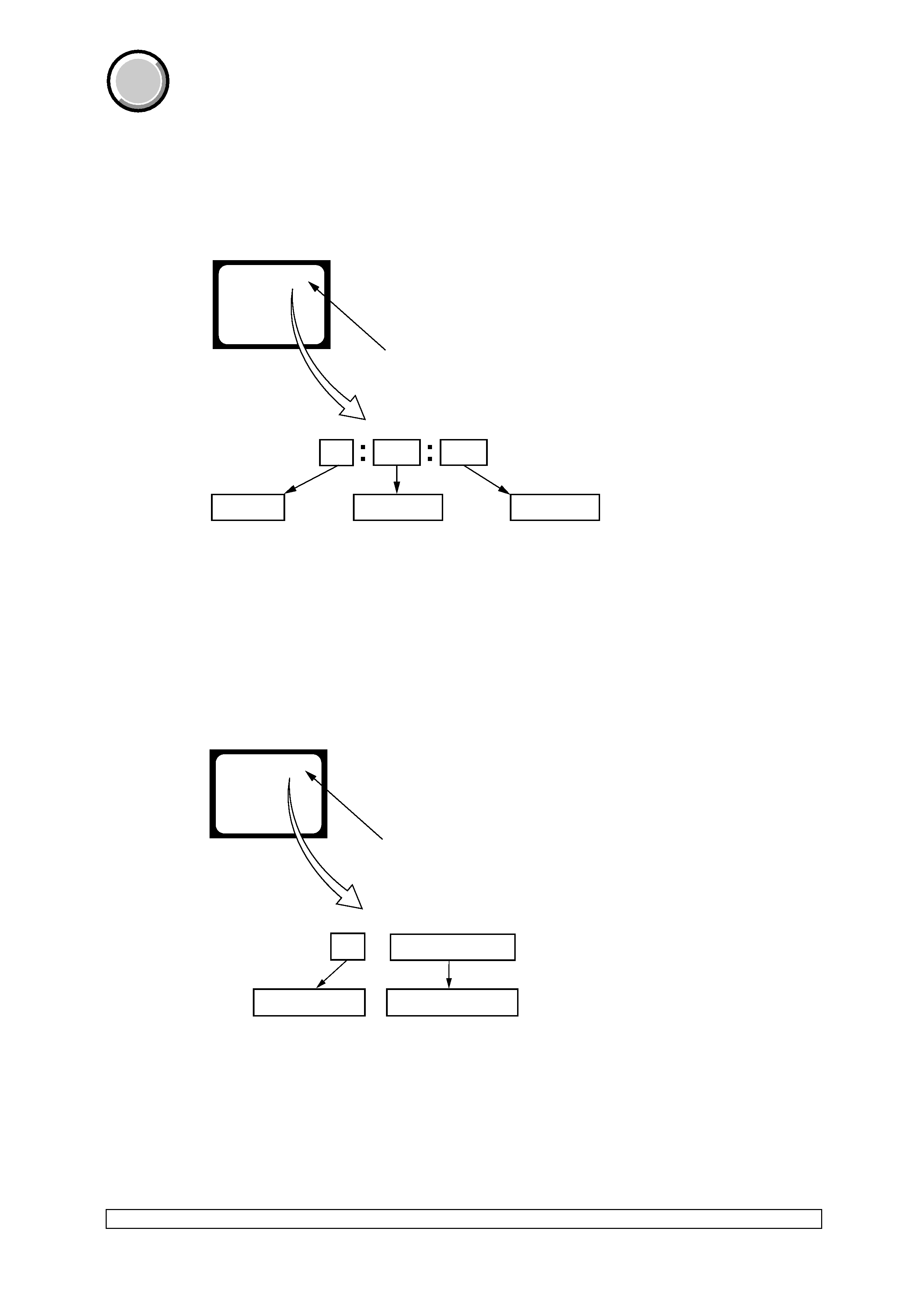
SELF-DIAGNOSIS DISPLAY
When problems occur while the unit is operating, the counter of the
viewfinder or LCD screen consists of an alphabet and 4-digit number,
which blinks at 3.2Hz. This 5-character display indicates the
"repaired by:", "block" in which the problem occurred, and "detailed
code" of the problem.
3.
SERVICE MODE DISPLAY
The service mode display shows the last self-diagnosis code shown in past.
3-1.
Display Method
While pressing the "BACK LIGHT" key, set the switch from OFF to ON, and continue pressing the "BACK LIGHT" key for 5 seconds
continuously. The service mode will be displayed, and the counter will show the backup No. and the 5-chracter self-diagnosis code.
3-2.
Backup No.
The backup No. in the [ ] indicates the order in which the problem occurred. (If the Number of problems which occurred is less than 6, only
the number of problems which occurred will be shown.)
[1] : Occurred first time
[4] : Occurred fourth time
[2] : Occurred second time
[5] : Occurred fifth time
[3] : Occurred third time
[6] : Occurred last time
Note:
Switching of destination can't be done.
3-3.
End of Display
Turning OFF the power supply will end the service mode display.
Note:
The self-diagnosis display data will be kept even if the lithium battery (BT4101 of the control switch block (PW-2980)) is removed.
1 1
3 1
C
Repaired by:
Refer to page 6.
Self-diagnosis Code Table.
Indicates the appropriate
step to be taken.
E.g.
31 ....Reload the tape.
32 ....Turn on power again.
Block
Detailed Code
Blinks at 3.2Hz
C : Corrected by customer
H : Corrected by dealer
E : Corrected by service
engineer
Viewfinder or LCD screen
C : 3 1 : 1 1
Order of previous errors
Backup No.
Self-diagnosis Codes
C : 3 1 : 1 1
[3]
Lights up
Viewfinder or LCD screen
[3] C : 3 1 : 1 1
SELF-DIAGNOSIS FUNCTION
COVER
COVER