SECTION 6
ADJUSTMENTS
Revision History
Revision History
Ver 1.1 2005.03
Sony EMCS Co.
2005C0500-1
© 2005.3
Published by DI Technical Support Section
9-876-865-52
DCR-DVD92/DVD92E/DVD103/DVD602/DVD602E/DVD653/DVD653E
Link
Link
Adjusting items when replacing main parts and boards
Before starting adjustments
Adjusting items when replacing main parts and boards
Before starting adjustments
VIDEO SYSTEM ADJUSTMENTS
ADJUSTMENT PROGRAM
INITIALIZATION OF 9, A, B, C, D, E, F, 13, 15,
17, 19, 1A, 1B, 1C, 1E, 1F PAGE DATA
PREPARATIONS BEFORE ADJUSTMENTS
ERROR
AUDIO SYSTEM ADJUSTMENTS
(DCR-DVD103/DVD653/DVD653E)
AUDIO SYSTEM ADJUSTMENTS
(DCR-DVD92/DVD92E/DVD602/DVD602E)
LCD/EVF SYSTEM ADJUSTMENTS
CAMERA SYSTEM ADJUSTMENTS
CAMERA SECTION ADJUSTMENTS
POWER ADJUSTMENT
DIAGNOSIS
DVD+RW ADJUSTMENT
DVD-RW ADJUSTMENT
TROUBLESHOOTING
DVD-R ADJUSTMENT
AUDIT (Drive Adjustment Program)
PREPARATIONS BEFORE ADJUSTMENTS
DRIVE SECTION ADJUSTMENTS
POWER ADJUSTMENT
DIAGNOSIS
DVD+RW ADJUSTMENT
DVD-RW ADJUSTMENT
TROUBLESHOOTING
DVD-R ADJUSTMENT
AUDIT (Drive Adjustment Program)
PREPARATIONS BEFORE ADJUSTMENTS
DRIVE SECTION ADJUSTMENTS
APPLICATION FOR ADJUSTMENT (SeusCam)
SERVICE MODE
DATA PROCESS
ADJUSTMENT REMOTE COMMANDER
SERVICE MODE
APPLICATION FOR ADJUSTMENT (SeusCam)
SERVICE MODE
DATA PROCESS
ADJUSTMENT REMOTE COMMANDER
SERVICE MODE
· Use this Service Manual together with the Automatic Adjustment Program (DCR-DVD92 Series Auto-Adj Ver1.[]r[][].exe)
and the AUDIT (Drive Adjustment Program).
Note: [] (numeric value) of the file name varies depending on the version of Automatic Adjustment Program.
DCR-DVD92/DVD92E/DVD103/DVD602/
DVD602E/DVD653/DVD653E
RMT-835
Auto-ADJ
Contents of LEVEL 2 and LEVEL 3 Service Manual
CONTENTS
1. SERVICE NOTE
2. DISASSEMBLY
3. BLOCK DIAGRAMS
4. PRINTED WIRING BOARDS AND
SCHEMATIC DIAGRAMS
5. REPAIR PARTS LIST
LEVEL 2
a
a
OVERALL
POWER
AV-094, CK-148, PD-251, SW-442 BOARD
FP-125, FP-126, FP-128, FP-129, FP-132, FP-133,
FP-135, FP-136, FP-234, FP-211, FP-228 FLEXIBLE
CONTROL SWITCH BLOCK (PS13300, SB9000)
MOTOR UNIT
EXPLODED VIEWS
ELECTRICAL PARTS
LEVEL 3
CD-563, VF-166,
MD-114, MD-120,
VC-395 BOARD
FP-211, FP-228
FLEXIBLE
a
-- 2 --
DCR-DVD92/DVD92E/DVD103/DVD602/DVD602E/DVD653/DVD653E
WARNING!!
WHEN SERVICING, DO NOT APPROACH THE LASER
EXIT WITH THE EYE TOO CLOSELY. IN CASE IT IS
NECESSARY TO CONFIRM LASER BEAM EMISSION,
BE SURE TO OBSERVE FROM A DISTANCE OF MORE
THAN
30
cm
FROM THE
SURFACE
OF THE
OBJECTIVE LENS ON THE OPTICAL PICK-UP BLOCK.
CAUTION:
The use of optical instrument with this product will increase eye
hazard.
CAUTION :
Danger of explosion if battery is incorrectly replaced.
Replace only with the same or equivalent type.
CAUTION
Use of controls or adjustments or perfor mance
procedures other than those specified herein may
result in hazardous radiation exposure.
Optical sensor disc (J-6082-570-A)
CAUTION
In the process of adjusting optical power,
CLASS1M laser optical radiates. so do not
remove this sensor disk.

-- 3 --
DCR-DVD92/DVD92E/DVD103/DVD602/DVD602E/DVD653/DVD653E
TABLE OF CONTENTS
6.
ADJUSTMENTS
Before Starting Adjustments ····················································· 6-1
1-1.
Adjusting Items when Replacing Main Parts and
Boards ·············································································· 6-2
6-1.
Camera Section Adjustments ··········································· 6-4
1-1.
Preparations before Adjustments (CAMERA Section) ··· 6-4
1-1-1. List of Service Tools ························································ 6-4
1-1-2. Preparations ····································································· 6-5
1-1-3. Precaution ········································································ 6-6
1.
Setting the Switch ···························································· 6-6
2.
Order of Adjustments ······················································ 6-6
3.
Subjects ··········································································· 6-6
1-2.
Initialization of 9, A, B, C, D, E, F, 13, 15, 17, 19,
1A, 1B, 1C, 1E, 1F Page Data ········································· 6-7
1-2-1. Initialization of 9, A, B, D, 13, 15, 17, 1A, 1B
Page Data ········································································· 6-7
1.
Initializing of 9, A, B, D, 13, 15, 17, 1A, 1B
Page Data ········································································· 6-7
2.
Modification of 9, A, B, D, 13, 15, 17, 1A, 1B
Page Data ········································································· 6-8
3.
9 Page Table ····································································· 6-8
4.
A Page Table ···································································· 6-9
5.
B Page Table ···································································· 6-9
6.
D Page Table ·································································· 6-10
7.
13 Page Table ································································· 6-10
8.
15 Page Table ································································· 6-10
9.
17 Page Table ································································· 6-10
10.
1A Page Table ································································ 6-11
11.
1B Page Table ································································ 6-11
1-2-2. Initialization of E, F, 19, 1E, 1F Page Data ··················· 6-12
1.
Initializing of E, F, 19, 1E, 1F Page Data ······················ 6-12
2.
Modification of E, F, 19, 1E, 1F Page Data ··················· 6-12
3.
E Page Table ·································································· 6-12
4.
F Page Table ·································································· 6-13
5.
19 Page Table ································································· 6-14
6.
1E Page Table ································································ 6-14
7.
1F Page Table ································································ 6-14
1-2-3.Initialization of C, 1C Page Data ··································· 6-15
1.
Initializing of C, 1C Page Data ····································· 6-15
2.
Modification of C, 1C Page Data ·································· 6-15
3.
Input of Board Type Data ·············································· 6-15
4.
C Page Table ·································································· 6-16
5.
1C Page Table ································································ 6-16
1-3.
Adjustment Program ······················································ 6-17
1.
Precautions When Using Automatic Adjustment
Program ········································································· 6-17
2.
Start of Automatic Adjustment Program ······················· 6-17
3.
Function of Each Button on Main Menu Screen ··········· 6-17
4.
Initializing of Flash Back Up ········································ 6-18
1-4.
Video System Adjustments ············································ 6-19
1.
Function of Each Button on Video System Adjustment
Screen ············································································ 6-19
2.
Adjustment Items of VIDEO System Adjustment ········· 6-19
3.
36 MHz Origin Oscillation Adjustment ························ 6-20
4.
VIDEO Adjustment ······················································· 6-20
1-5.
Camera System Adjustments ········································· 6-22
1.
Function of Each Button on Camera System
Adjustment Screen ························································ 6-22
2.
Adjustment Items of Camera System Adjustment ········ 6-23
3.
CAMERA Adjustment 1 ··············································· 6-24
4.
CAMERA Adjustment 2 (Using the minipattern box
or flange back adjustment jig) ······································· 6-25
5.
CAMERA Adjustment 2 (Using the flange back
adjustment chart and subject more than 500 m away) ·· 6-25
5-1.
CAMERA Adjustment 2 (1) ·········································· 6-26
5-2.
CAMERA Adjustment 2 (2) ·········································· 6-26
Section
Title
Page
Section
Title
Page
6.
CAMERA Adjustment 3 ··············································· 6-27
7.
Optical Axis Adjustment ··············································· 6-28
8.
CAMERA Adjustment 4 ··············································· 6-29
9.
CAMERA Adjustment 5 ··············································· 6-32
1-6.
LCD/EVF System Adjustments ····································· 6-33
1.
Function of Each Button on LCD/EVF System
Adjustment Screen ························································ 6-33
2.
Adjustment Items of LCD/EVF System Adjustment ···· 6-33
3.
LCD/EVF Adjustment ··················································· 6-34
1-7.
Audio System Adjustments
(DCR-DVD92/DVD92E/DVD602/DVD602E) ············· 6-36
1.
Overall Level Characteristics Check ····························· 6-36
2.
Overall Distortion Check ··············································· 6-36
3.
Overall Noise Level Check ············································ 6-37
1-8.
Audio System Adjustments
(DCR-DVD103/DVD653/DVD653E) ··························· 6-38
1.
Overall Level Characteristics Check ····························· 6-38
2.
Overall Distortion Check ··············································· 6-38
3.
Overall Noise Level Check ············································ 6-38
1-9.
Error ··············································································· 6-39
1-9-1. Error Message ································································ 6-39
1.
Connect Error ································································ 6-39
2.
RESET the CAMERA and Try Again ··························· 6-39
3.
Adjustment Time Out ···················································· 6-39
4.
Adjustment NG ······························································ 6-39
1-9-2. Precautions When an Error Occurred ···························· 6-40
6-2.
Drive Section Adjustments ············································ 6-41
2-1.
Preparations Before Adjustments (Drive Section) ········ 6-41
2-1-1. List of Service Tools ······················································ 6-41
2-1-2. Connection ····································································· 6-42
2-1-3. How to Set the Optical Sensor Disc ······························ 6-43
2-1-4. Precautions on Adjustment ············································ 6-43
1.
Adjustment Data ···························································· 6-43
2.
Order of Adjustment ······················································ 6-43
3.
Precaution on the Laser Diode ······································ 6-43
2-1-5. Alignment Disc ······························································ 6-44
2-2.
AUDIT (Drive Adjustment Program) ···························· 6-45
2-2-1. Installation Method ························································ 6-45
2-2-2. AUDIT Starting Method ················································ 6-45
2-2-3. Description of Screen ···················································· 6-45
1.
Diagnosis Section ·························································· 6-46
2.
Adjustment Section ······················································· 6-46
3.
Comment Display Section ············································· 6-46
4.
Status Display Section ··················································· 6-46
5.
[SET] Button (After completing the TEST) ················· 6-46
6.
[STOP] Button ······························································ 6-46
7.
Menu Section ································································· 6-46
8.
Caution Display Section ················································ 6-46
2-3.
Diagnosis ······································································· 6-47
2-3-1. Menu in Diagnosis Section ············································ 6-47
2-3-2. Diagnosis Method ·························································· 6-47
2-4.
POWER Adjustment ······················································ 6-49
2-4-1. Menu in POWER Adjustment Section ·························· 6-49
2-4-2. Adjusting Method ·························································· 6-50
2-5.
DVD-R Adjustment ······················································· 6-51
2-5-1. Menu in DVD-R Adjustment Section ···························· 6-51
2-5-2. Adjusting Method ·························································· 6-52
2-6.
DVD-RW Adjustment ··················································· 6-53
2-6-1. Menu in DVD-RW Adjustment Section ························ 6-53
2-6-2. Adjusting Method ·························································· 6-54
2-7.
DVD+RW Adjustment ··················································· 6-55
2-7-1. Menu in DVD+RW Adjustment Section ······················· 6-55
2-7-2. Adjusting Method ·························································· 6-55
2-8.
Troubleshooting ····························································· 6-56
2-8-1. Fundamental Troubleshooting Flow ······························ 6-56
2-8-2. Diagnosis ······································································· 6-58

-- 4 --
DCR-DVD92/DVD92E/DVD103/DVD602/DVD602E/DVD653/DVD653E
Section
Title
Page
2-8-3. Power Adjust ································································· 6-60
2-8-4. DVD-R Adjust ······························································· 6-62
2-8-5. DVD-RW Adjust ··························································· 6-63
2-8-6. DVD+RW Adjust ··························································· 6-64
6-3.
Service Mode ································································· 6-65
3-1.
Adjustment Remote Commander ·································· 6-65
1.
Using the Adjustment Remote Commander ·················· 6-65
2.
Precautions Upon Using the Adjustment Remote
Commander ··································································· 6-65
3-2.
Application for Adjustment (SeusCam) ························ 6-66
1.
Connection ····································································· 6-66
2.
Operation ······································································· 6-66
3.
Difference in Display Between SeusCam and
Adjustment Remote Commander ·································· 6-66
4.
Precaution on Use of SeusCam ····································· 6-66
3-3.
Data Process ·································································· 6-67
3-4.
Service Mode ································································· 6-68
1.
Setting the Test Mode ···················································· 6-68
2.
Emergence Memory Address ········································ 6-68
2-1.
Emergency Memory Address (Camera section) ············ 6-68
2-2.
EMG Code (Emergency Code) ····································· 6-68
3.
Bit Value Discrimination ··············································· 6-69
4.
Lens Barrior Check
(DCR-DVD103/DVD653/DVD653E only) ·················· 6-69
5.
Switch Check ································································· 6-70
6.
Jack Check (1) ······························································· 6-70
7.
Jack Check (2) ······························································· 6-71
8.
LED Check ···································································· 6-71
9.
Record Data Check ························································ 6-71
9-1.
Record of Use Check ····················································· 6-71
9-2.
Record of Self-diagnosis Check ···································· 6-72
9-3.
How to Reset the Record of Use and Record of
Self-diagnosis ································································ 6-73
* The camera optical axis frame is shown on page 6-74.
The camera color reproduction frame is shown on page
6-75.
6-1
DCR-DVD92/DVD92E/DVD103/DVD602/DVD602E/DVD653/DVD653E
SECTION 6
ADJUSTMENTS
1.
Before starting adjustments
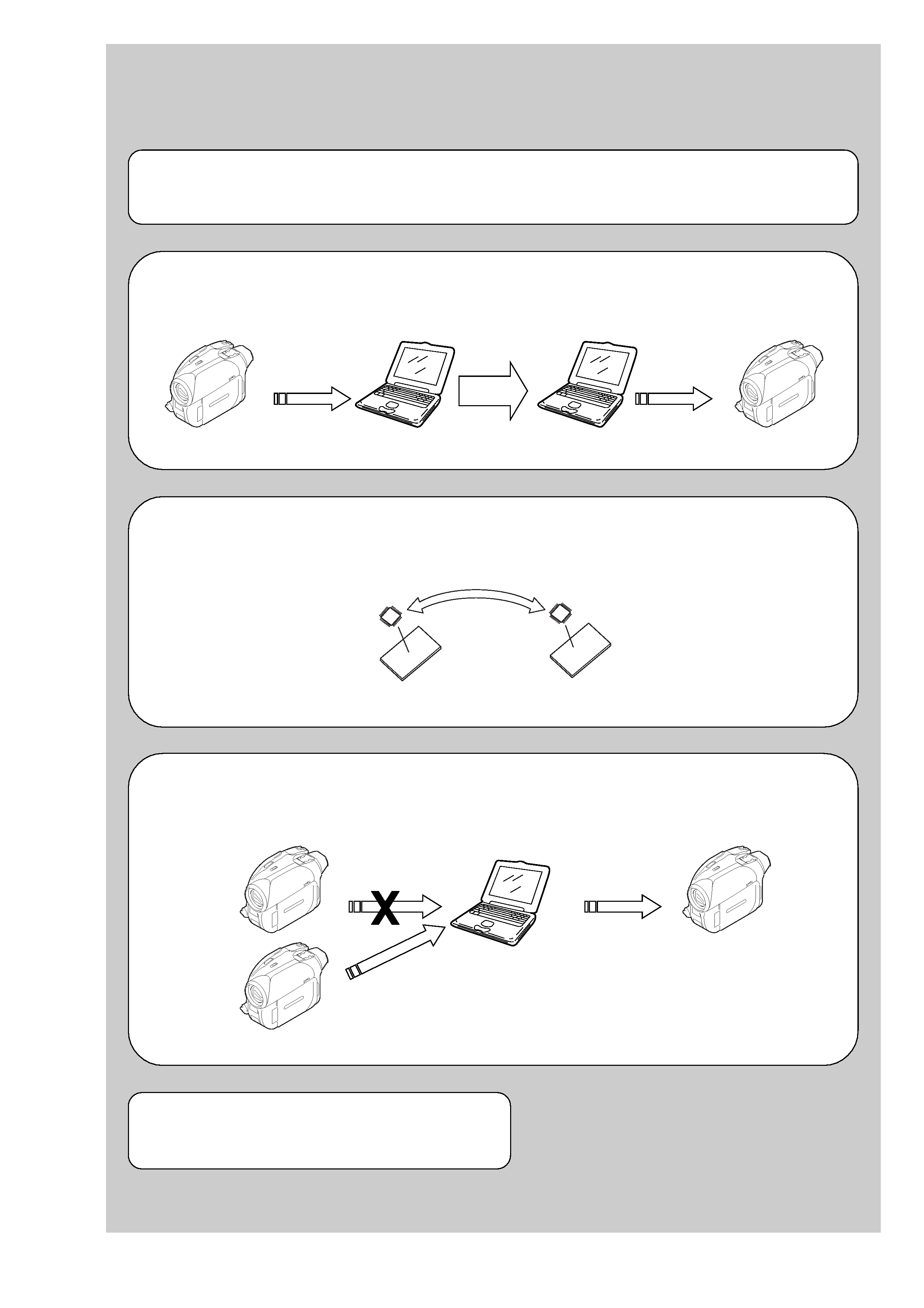
EVR Data Re-writing Procedure When Replacing Board
The data that is stored in the repair board, is not necessarily correct.
Perform either procedure 1 or procedure 2 or procedure 3 when replacing board.
Procedure 1
Save the EVR data of the machine in which a board is going to be replaced. Download the saved data after a
board is replaced.
Remove the EEPROM and install it.
(Former board)
(New board)
Procedure 2
Remove the EEPROM from the board of the machine that is going to be repaired. Install the removed
EEPROM to the replaced board.
Procedure 3
When the data cannot be saved due to defective EEPROM, or when the EEPROM cannot be removed or
installed, save the data from the same model of the same destination, and download it.
After the EVR data is saved and downloaded, check the
respective items of the EVR data.
(Refer to page 6-3 for the items to be checked)
(Machine before starting repair)
(Machine after a board is replaced)
PC
PC
Save the EVR data
to a personal computer.
Download the saved
data to a machine.
(Machine to be repaired)
(Machine to be repaired)
(The same model of the same destination)
Save the data.
Download the data.
PC