DAV-S500/S800
US Model
Canadian Model
Chinese Model
DAV-S500
AEP Model
UK Model
Australian Model
E Model
DAV-S500/S800
SERVICE MANUAL
COMPACT AV SYSTEM
Sony Corporation
Home Audio Company
Shinagawa Tec Service Manual Production Group
9-873-259-01
2001G1600-1
© 2001.7
· DAV-S500/S800 are composed of following models. As
for the service manual, it is issued for each component
model, then, please refer to them.
Ver 1.0 2001. 07
PARTS LIST
Part No.
Description
Remarks
1-476-784-11 REMOTE COMMANDER (RM-SS800)
1-573-291-11 CONNECTOR, CONVERSION
0 1-569-008-21 ADAPTOR, CONVERSION 2P (E32, SP, MY, EA)
1-754-060-11 ANTENNA (FM)
1-754-149-11 LOOP ANT (AM)
1-769-108-11 CORD, CONNECTION (VIDEO)
0 1-770-019-11 ADAPTOR, CONVERSION PLUG 3P (UK, HK)
1-792-388-14 CORD (WITH CONNECTOR) (RED, 5m) (S500)
1-792-388-24 CORD (WITH CONNECTOR) (BLK, 5m) (S500)
1-792-388-34 CORD (WITH CONNECTOR) (WHT, 5m) (S500)
1-792-388-44 CORD (WITH CONNECTOR) (YEL, 15m) (S500)
1-792-388-54 CORD (WITH CONNECTOR) (BLU, 15m) (S500)
1-792-388-64 CORD (WITH CONNECTOR) (GRN, 5m) (S500)
1-823-352-11 CORD (WITH CONNECTOR) (RED, 5m) (S800)
1-823-352-21 CORD (WITH CONNECTOR) (PURPLE, 5m) (S800)
1-823-352-31 CORD (WITH CONNECTOR) (WHT, 5m) (S800)
1-823-352-41 CORD (WITH CONNECTOR) (GRY, 15m) (S800)
1-823-352-51 CORD (WITH CONNECTOR) (BLU, 15m) (S800)
1-823-352-61 CORD (WITH CONNECTOR) (GRN, 5m) (S800)
4-235-055-01 COVER, BATTERY (FOR RM-SS800)
4-235-681-11 MANUAL, INSTRUCTION (ENGLISH) (S500)
4-235-681-21 MANUAL, INSTRUCTION (FRENCH) (S500)
4-235-681-31 MANUAL, INSTRUCTION (SPANISH) (S500)
4-235-681-41 MANUAL, INSTRUCTION (CHINESE) (S500)
4-235-681-51 MANUAL, INSTRUCTION (ARABIC) (S500)
4-235-681-61 MANUAL, INSTRUCTION (KOREAN) (S500)
4-235-681-71 MANUAL, INSTRUCTION (PORTUGUESE) (S500)
4-236-189-11 MANUAL, INSTRUCTION (ENGLISH) (S800)
4-236-189-21 MANUAL, INSTRUCTION (FRENCH) (S800)
4-236-189-31 MANUAL, INSTRUCTION (GERMAN, SPANISH, DUTCH,
SWEDISH, ITALIAN, POLISH) (S800)
4-236-189-41 MANUAL, INSTRUCTION
(DANISH, FINNISH, PORTUGUESE) (S800)
4-236-189-51 MANUAL, INSTRUCTION (ARABIC) (S800)
4-236-189-61 MANUAL, INSTRUCTION (RUSSIAN) (S800)
4-236-189-71 MANUAL, INSTRUCTION (CHINESE) (S800)
4-236-526-11 MANUAL, INSTRUCTION (ENGLISH) (S500)
4-236-526-21 MANUAL, INSTRUCTION (FRENCH) (S500)
4-236-526-31 MANUAL, INSTRUCTION (GERMAN, SPANISH, DUTCH,
SWEDISH, ITALIAN, POLISH) (S500)
4-236-526-41 MANUAL, INSTRUCTION
(DANISH, FINNISH, PORTUGUESE) (S500)
4-236-887-01 CUSHION (FOR SS-RS500/TS500)
Part No.
Description
Remarks
DAV-S500
HCD-S500
SS-TS500
SS-RS500
SS-RS500
SS-WS500
DAV-S800
HCD-S800
SS-TS550
SS-CT550
SS-RS550
SS-WS550
COMPACT DISC DECK RECEIVER SYSTEM
FRONT SPEAKER SYSTEM
CENTER SPEAKER SYSTEM
REAR SPEAKER SYSTEM
SUBWOOFER SPEAKER SYSTEM
COMPONENT MODEL NAME
· Abbreviation
AUS : Australian model
E32 : 110-240V AC area in E model
EA : Saudi Arabia model
HK : Hong Kong model
MY : Malaysia model
SP
: Singapore model
The components identified by
mark
0 or dotted line with mark
0 are critical for safety.
Replace only with part number
specified.
Les composants identifiés par
une marque
0 sont critiques
pour la sécurité.
Ne les remplacer que par une
pièce portant le numéro spécifié.

DAV-S500/S800
REVISION HISTORY
Clicking the version allows you to jump to the revised page.
Also, clicking the version at the upper right on the revised page allows you to jump to the next revised
page.
Ver.
Date
Description of Revision
1.0
2001.07
New
HCD-S500/S800
US Model
Canadian Model
HCD-S500
AEP Model
UK Model
E Model
Australian Model
HCD-S500/S800
SERVICE MANUAL
COMPACT AV SYSTEM
Sony Corporation
Audio Group
Published by Sony Engineering Corporation
9-873-291-09
2004H16-1
© 2004.08
HCD-S500/S800 are the amplifier, DVD/CD and
tuner section in DAV-S500/S800.
SPECIFICATIONS
Ver 1.8 2004.08
AUDIO POWER SPECIFICATIONS
POWER OUTPUT AND TOTAL HARMONIC DISTORTION:
With 6 ohm loads, both channels driven, from 120 10,000 Hz; rated
40 watts per channel minimum RMS power, with no more than 10 %
total harmonic distortion from 250 milliwatts to rated output.
Amplifier section
S500 MODEL
Stereo mode
40 W + 40 W (6 ohms at 1 kHz, THD 10 %)
Surround mode
Front: 40 W + 40 W
Center*: 40 W
Rear*: 40 W + 40 W (6 ohms at 1 kHz, THD 10 %)
Subwoofer*: 80 W (3 ohms at 100 Hz, THD 10 %)
S800 MODEL
Stereo mode
50 W + 50 W (6 ohms at 1 kHz, THD 10 %)
Surround mode
Front: 50 W + 50 W
Center*: 50 W
Rear*: 50 W + 50 W (6 ohms at 1 kHz, THD 10 %)
Subwoofer*: 100 W (3 ohms at 100 Hz, THD 10 %)
* Depending on the sound field settings and the source, there may be no sound output.
Inputs (Analog)
VIDEO 1, 2:
Sensitivity: 150 mV
Impedance: 50 kilohms
Inputs (Digital)
VIDEO 2 (optical):
Sensitivity:
Outputs (Analog)
VIDEO 1 (AUDIO OUT):
Voltage: 2 V
Impedance: 1 kilohms
PHONES:
Accepts low- and high-impedance headphones
Outputs (Digital)
DIGITAL OUT (CD)
Sensitivity:
SACD/DVD system
Laser
Semiconductor laser
Signal format system
NTSC or NTSC/PAL
Frequency response (at 2 CH STEREO mode)
DVD (PCM): 2 Hz to 22 kHz (
±1.0 dB)
CD: 2 Hz to 20 kHz (
±1.0 dB)
Signal-to-noise ratio
More than 80 dB (VIDEO 1 (AUDIO) connectors only)
Harmonic distortion
Less than 0.03 %
FM tuner section
System
PLL quartz-locked digital synthesizer system
Tuming range:
US, Canadian models:
Tuming range:
87.5 108.0 MHz (50 kHz step)
Antenna
FM wire antenna
Antenna terminals
75 ohms, unbalanced
Intermediate frequency
10.7 MHz
AM tuner section
System
Tuner section:
PLL quartz-locked digital synthesizer system
Tuning range
US, Canadian models:
1,710 kHz (with the interval set at 10 kHz)
531 1,710 kHz (with the interval set at 9 kHz)
AEP, UK, Saudi Arabia models:
531 1,602 kHz (with the interval set at 9 kHz)
Other models:
531 1,602 kHz (with the interval set at 9 kHz)
530 1,710 kHz (with the interval set at 10 kHz)
Antenna
Loop antenna
Video section
Inputs
Video: 1 Vp-p 75 ohms
Outputs
Video: 1 Vp-p 75 ohms
S-video:
Y: 1 Vp-p 75 ohms
C: 0.286 Vp-p 75 ohms
General
Power requirements
US, Canadian models:
120 V AC, 60 Hz
AEP, UK models:
220 240 V AC, 50/60 Hz
Australian and E models:
220 240 V AC, 50/60 Hz
Mexican model:
120 V AC, 60 Hz
Other models:
110 240 V/220 240 V AC, 50/60 Hz
Power consumption
98 W (120 V AC) 98 W (230 V AC)
Dimensions (approx.)
355
× 70 × 378 mm (14 × 2 7/8 × 15 inches) (w/h/d) incl. projecting parts
Mass (approx.)
4.0 kg (9 lb 8 oz)
Operating temperature
5°C to 35°C (41°F to 95°F)
Operating humidity
5 % to 90 %
Supplied accessories
Design and specifications are subject to change without notice.
Check that you have the following items:
Speakers (5)
·
·
Subwoofer (1)
· AM loop antenna (1)
· FM wire antenna (1)
· Speaker cords (5m
× 4, 15m × 2) (16ft. × 4, 49ft. × 2)
· Video cord (1)
· Remote commander (remote) RM-SS800 (1)
· R6 (size AA) batteries (2)
· Foot pads (15)
· Speakers-connection and Installation (card) (1)
· Quick reference for Remote commander (card) (1)
Tuming range:
87.5
Tuming range:
Other
108.0 MHz (100 kHz step)
530
Model Name Using Similar Mechanism
NEW
Mechanism Type
CDM-55D-DVBU8
Base Unit Name
DVBU8
Optical Pick-up Name
KHM-240AAA
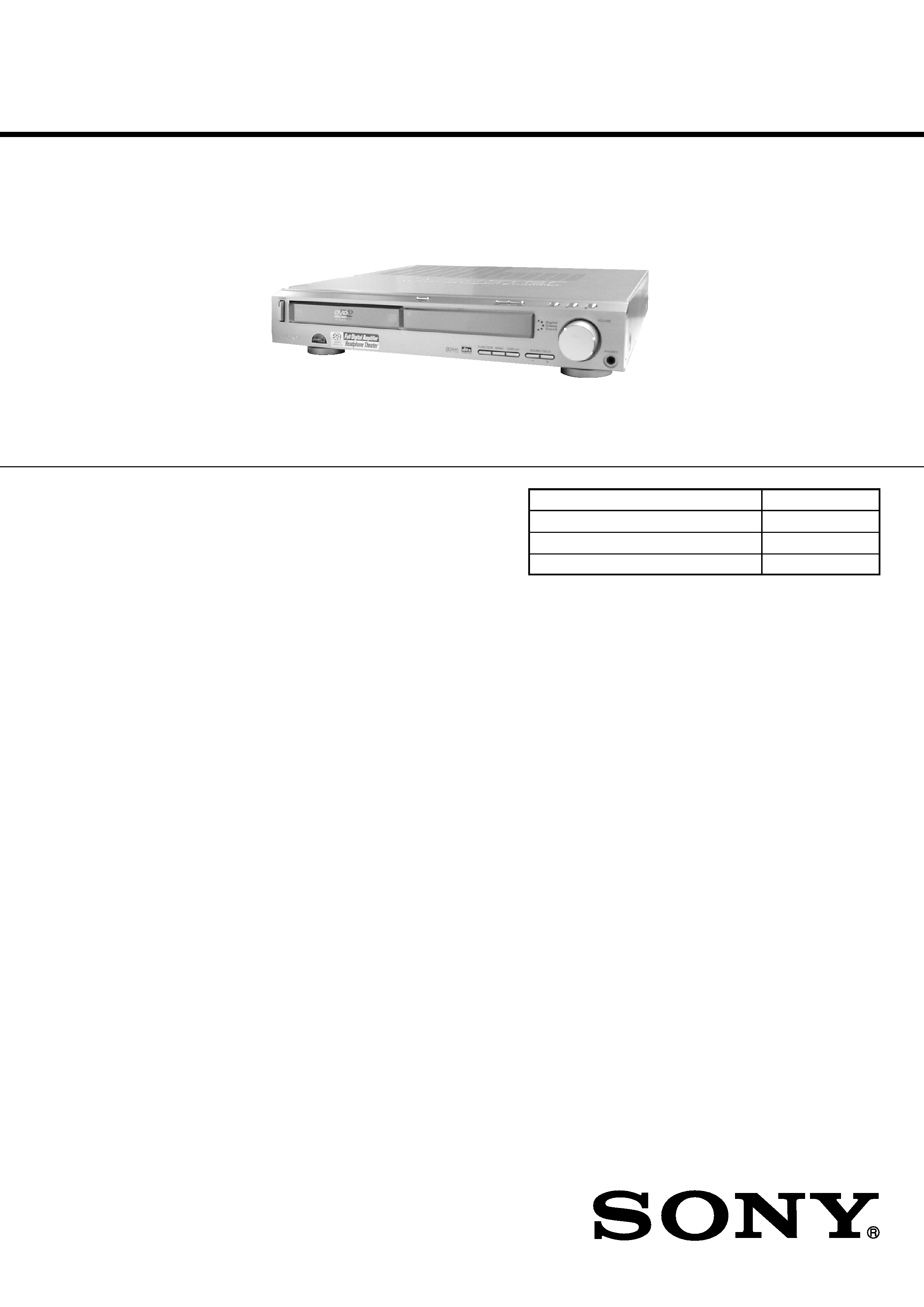
Photo : HCD-S500
2
HCD-S500/S800
SAFETY CHECK-OUT
After correcting the original service problem, perform the following
safety checks before releasing the set to the customer:
Check the antenna terminals, metal trim, "metallized" knobs, screws,
and all other exposed metal parts for AC leakage. Check leakage as
described below.
LEAKAGE
The AC leakage from any exposed metal part to earth Ground and
from all exposed metal parts to any exposed metal part having a
return to chassis, must not exceed 0.5 mA (500 microampers).
Leakage current can be measured by any one of three methods.
1.
A commercial leakage tester, such as the Simpson 229 or RCA
WT-540A. Follow the manufacturers' instructions to use these
instruments.
2.
A battery-operated AC milliammeter. The Data Precision 245
digital multimeter is suitable for this job.
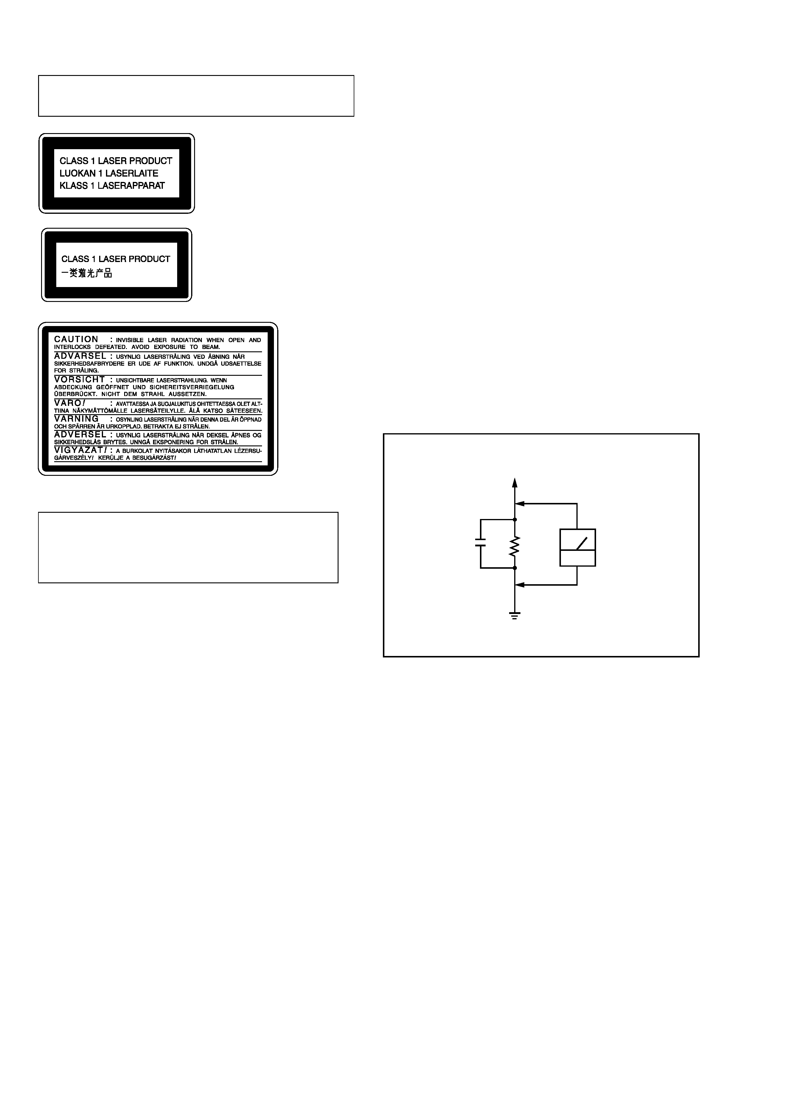
3.
Measuring the voltage drop across a resistor by means of a
VOM or battery-operated AC voltmeter. The "limit" indication
is 0.75 V, so analog meters must have an accurate low-voltage
scale. The Simpson 250 and Sanwa SH-63Trd are examples of
a passive VOM that is suitable. Nearly all battery operated
digital multimeters that have a 2V AC range are suitable. (See
Fig. A)
Fig. A. Using an AC voltmeter to check AC leakage.
0.15
µF
To Exposed Metal
Parts on Set
1.5k
AC
voltmeter
(0.75V)
Earth Ground
CAUTION
Use of controls or adjustments or performance of procedures
other than those specified herein may result in hazardous
radiation exposure.
Notes on chip component replacement
·Never reuse a disconnected chip component.
· Notice that the minus side of a tantalum capacitor may be
damaged by heat.
Flexible Circuit Board Repairing
·Keep the temperature of soldering iron around 270°C
during repairing.
· Do not touch the soldering iron on the same conductor of the
circuit board (within 3 times).
· Be careful not to apply force on the conductor when soldering
or unsoldering.
Laser component in this product is capable of emitting radiation
exceeding the limit for Class 1.
This appliance is classified as
a CLASS 1 LASER product.
The
CLASS
1
LASER
PRODUCT MARKING is
located on the rear exterior.
This caution
label is located
inside the unit.
SAFETY-RELATED COMPONENT WARNING!!
COMPONENTS IDENTIFIED BY MARK 0 OR DOTTED LINE WITH
MARK 0 ON THE SCHEMATIC DIAGRAMS AND IN THE PARTS
LIST ARE CRITICAL TO SAFE OPERATION. REPLACE THESE
COMPONENTS WITH SONY PARTS WHOSE PART NUMBERS
APPEAR AS SHOWN IN THIS MANUAL OR IN SUPPLEMENTS
PUBLISHED BY SONY.
ATTENTION AU COMPOSANT AYANT RAPPORT
À LA SÉCURITÉ!
LES COMPOSANTS IDENTIFÉS PAR UNE MARQUE 0 SUR LES
DIAGRAMMES SCHÉMATIQUES ET LA LISTE DES PIÈCES SONT
CRITIQUES POUR LA SÉCURITÉ DE FONCTIONNEMENT. NE
REMPLACER CES COMPOSANTS QUE PAR DES PIÈSES SONY
DONT LES NUMÉROS SONT DONNÉS DANS CE MANUEL OU
DANS LES SUPPÉMENTS PUBLIÉS PAR SONY.
NOTE OF REPLACING THE DVD BOARD
When replacing the DVD board, since the adjustment value is not
set up correctly, "Drive Auto Adjustment" can't be performed.
In this case, initialize Memory in the following procedures.
Procedure:
1.Starting test mode. (See page 12)
2.Press the [2] key of the remote commander, and set the "DRIVE
MANUAL OPERATION". (See page 18)
3.Press the [6] key of the remote commander, and set the "6. Memory
Check". (See page 20)
4.Press the [CLEAR] key of the remote commander, and initialize
Memory.
Ver 1.8
3
HCD-S500/S800
TABLE OF CONTENTS
1. SERVICING NOTE ·························································· 5
2. GENERAL ·········································································· 6
3. DISASSEMBLY ································································ 8
4. TEST MODE ···································································· 12
5. ELECTRICAL ADJUSTMENT ·································· 22
6. DIAGRAMS ······································································ 25
6-1. Block Diagrams ··························································· 26
RF/Servo, Video Section ······································· 26
CPU Section ·························································· 27
Power Section ························································ 28
6-2. Printed Wiring Board RF Section ························· 29
6-3. Schematic Diagram RF Section ··························· 30
6-4. Printed Wiring Board DVD Section (1/2) ············ 31
6-5. Printed Wiring Board DVD Section (2/2) ············ 32
6-6. Schematic Diagram DVD (1/8) Section ··············· 33
6-7. Schematic Diagram DVD (2/8) Section ··············· 34
6-8. Schematic Diagram DVD (3/8) Section ··············· 35
6-9. Schematic Diagram DVD (4/8) Section ··············· 36
6-10. Schematic Diagram DVD (5/8) Section ··············· 37
6-11. Schematic Diagram DVD (6/8) Section ··············· 38
6-12. Schematic Diagram DVD (7/8) Section ··············· 39
6-13. Schematic Diagram DVD (8/8) Section ··············· 40
6-14. Printed Wiring Board AMP Section (1/2) ············ 41
6-15. Printed Wiring Board AMP Section (2/2) ············ 42
6-16. Schematic Diagram AMP Section (1/2) ··············· 43
6-17. Schematic Diagram AMP Section (2/2) ··············· 44
6-18. Printed Wiring Board I/O Section ························ 45
6-19. Schematic Diagram I/O Section (1/2) ·················· 46
6-20. Schematic Diagram I/O Section (2/2) ·················· 47
6-21. Printed Wiring Board Panel Section ····················· 48
6-22. Schematic Diagram Panel Section ······················· 49
6-23. Printed Wiring Board Front Section ····················· 50
6-24. Schematic Diagram Front Section ························ 51
6-25. Printed Wiring Board Power Section ···················· 52
6-26. Printed Wiring Board Power Section ··················· 53
6-27. Schematic Diagram Power Section ······················ 54
6-28. Schematic Diagram Loading Section ··················· 55
6-29. Printed Wiring Board Loading Section ················ 55
6-30. IC Block Diagrams ······················································ 56
6-31. IC Pin Function Description ········································ 60
7. EXPLODED VIEWS
7-1. Main Section ······························································· 70
7-2. Front Panel Section ····················································· 71
7-3. Chassis Section ···························································· 72
7-4. Mechanism Deck Section (CDM55D-DVBU8) ············ 74
8. ELECTRICAL PARTS LIST ······································· 75
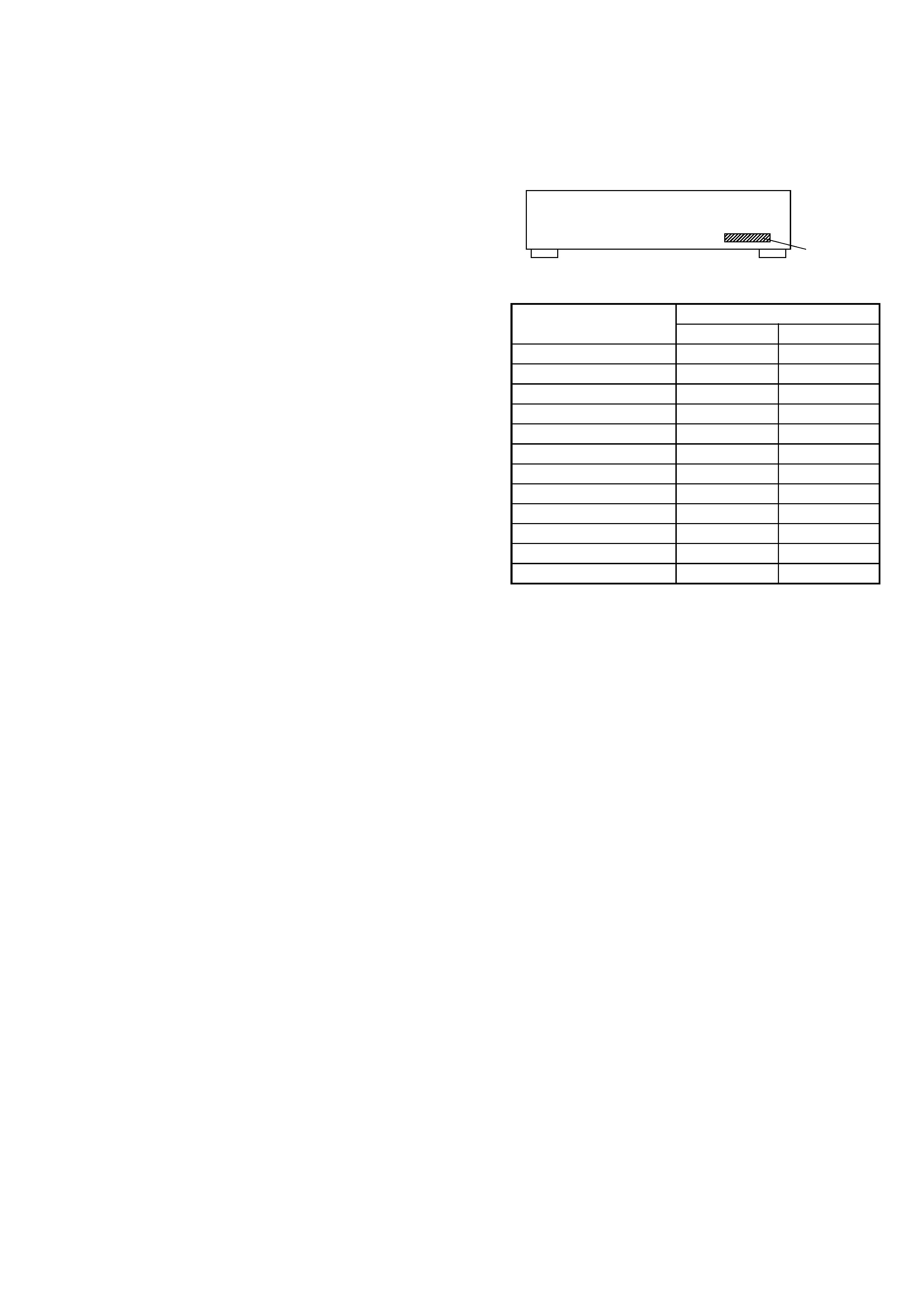
MODEL IDENTIFICATION
-- BACK PANEL --
Part No.
·Abbreviation
E12
: 220-240V AC area in E model
E32
: 110-240V AC area in E model
Model
US, Canadian models
AEP, UK models
Mexican model
E32 model
Australian model
Malaysia, Singapore models
E12 model
Taiwan model
Argentine model
Saudi Arabia model
Hong Kong model
CIS model
PARTS No.
DAV-S500
DAV-S800
4-234-914-0s
---------------------
4-236-491-2s
4-234-914-1s
4-234-914-2s
4-236-126-6s
4-234-914-3s
---------------------
4-234-914-4s
4-237-482-5s
4-234-914-5s
---------------------
4-234-914-6s
---------------------
4-234-914-7s
4-237-482-6s
4-234-914-8s
---------------------
4-234-914-9s
4-237-482-3s
4-237-482-0s
4-237-482-4s
4-237-482-7s
4-237-482-2s
Ver 1.3 2002.07