SERVICE MANUAL
Sony Corporation
Audio Group
Published by Sony Engineering Corporation
US Model
Canadian Model
AEP Model
UK Model
E Model
DVD HOME THEATRE SYSTEM
9-879-138-01
2004H16-1
© 2004.08
Ver 1.0 2004.08
DAV-LF1
·DAV-LF1 is composed of following models.
As service manuals are issued for each component
model, please refer to them.
PARTS LIST
Part No.
Description
Remark
ACCESSORIES
************
1-478-699-11 COMMANDER, STANDARD (RM-SP320)
(including a BATTERY COVER)
1-479-044-11 RAY-CATCHER UNIT, INFRARED RAY
(for REMOTE CONTROL)
0 1-569-008-12 ADAPTOR, CONVERSION 2P (SP)
1-751-619-23 CORD, CONNECTION (VIDEO) (EXCEPT AEP, UK, RU)
1-754-059-12 ANTENNA, LOOP (AM)
1-793-184-23 CONNECTOR (F TYPE ADAPTOR) (FM)
2-108-606-12 MANUAL, INSTRUCTION (ENGLISH) (AEP, UK, RU)
2-108-606-22 MANUAL, INSTRUCTION (FRENCH, GERMAN, SPANISH)
(AEP)
2-108-606-32 MANUAL, INSTRUCTION
(DUTCH, ITALIAN, SWEDISH, POLISH) (AEP)
2-108-606-41 MANUAL, INSTRUCTION (RUSSIAN) (RU)
2-177-084-01 COVER (S) (for FRONT and SURROUND speakers)
2-190-827-12 MANUAL, INSTRUCTION (ENGLISH)
(US, CND, E41, EA, SP, HK)
2-190-827-22 MANUAL, INSTRUCTION (FRENCH) (CND, EA, SP)
2-190-827-31 MANUAL, INSTRUCTION (SPANISH) (E41, SP, MX)
2-190-827-41 MANUAL, INSTRUCTION (CHINESE) (SP, HK)
2-190-827-51 MANUAL, INSTRUCTION (KOREAN) (KR)
2-190-827-61 MANUAL, INSTRUCTION (ARABIC) (EA)
2-190-828-12 MANUAL, INSTRUCTION (DANISH,FINNISH,PORTUGUESE)
(AEP)
2-190-828-21 MANUAL, INSTRUCTION (GREEK) (AEP)
2-190-828-31 MANUAL, INSTRUCTION (CZECH,HUNGARIAN) (AEP)
2-190-828-41 MANUAL, INSTRUCTION (TURKISH) (AEP)
2-190-828-51 MANUAL, INSTRUCTION (SLOVAK) (AEP)
3-073-861-01 CLOTH (TL), CLEANING
A-1071-985-A DIR-R3 (RECEIVER)
A-4718-204-A DIR-T1 (TRANSMITTER)
COMPONENT MODEL NAME
DAV-LF1
CONTROL UNIT
HCD-LF1
(SACD/DVD RECEIVER)
FRONT SPEAKER
L
SS-TSLF1L
R
SS-TSLF1
SURROUND SPEAKER
L
SA-TSLF1
R
SS-TSLF1W
CENTER SPEAKER
SS-CTLF1
SUB WOOFER
SA-WSLF1
·Abbreviation
CND : Canadian model
E41 : Chilean and Peru models
EA
: Saudi Arabia model
HK
: Hong Kong model
KR
: Korea model
MX : Mexican model
RU
: Russian model
SP
: Singapore model
The components identified by
mark 0 or dotted line with mark
0 are critical for safety.
Replace only with part number
specified.
Les composants identifiés par
une marque 0 sont critiques
pour la sécurité.
Ne les remplacer que par une
pièce portant le numéro spécifié.

DAV-LF1
REVISION HISTORY
Clicking the version allows you to jump to the revised page.
Also, clicking the version at the upper right on the revised page allows you to jump to the next revised
page.
Ver.
Date
Description of Revision
1.0
2004.08
New
SERVICE MANUAL
Sony Corporation
Home Audio Division
Published by Sony Techno Create Corporation
US Model
Canadian Model
AEP Model
UK Model
E Model
Australian Model
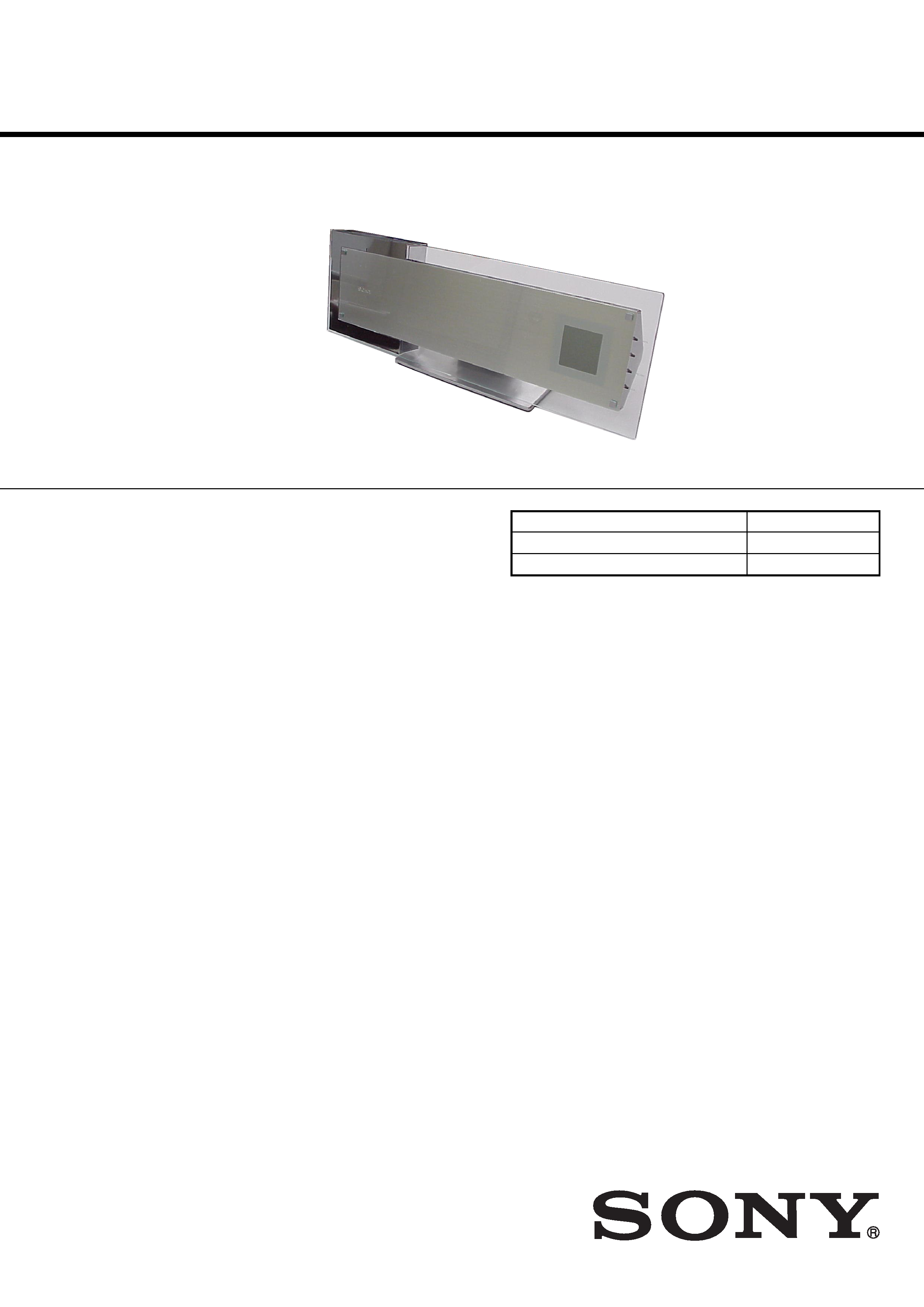
SUPER AUDIO CD/DVD PLAYER
9-879-139-03
2005I16-1
© 2006.09
Ver 1.2 2006.09
SPECIFICATIONS
HCD-LF1
· HCD-LF1 is DVD/CD DECK system in DAV-LF1.
Model Name Using Similar Mechanism
NEW
Mechanism Type
CDM80AT-DVBU29T
Optical Pick-up Name
DBU-3
* Manufactured under license from Dolby Laboratories.
"Dolby", "Pro Logic", and the double-D symbol are trademarks
of Dolby Laboratories.
**Manufactured under license from Digital Theater Systems, Inc.
"DTS", "DTS-ES", and "DTS Digital Surround" are trademarks
of Digital Theater Systems, Inc.
Super Audio CD/DVD system
Laser
Semiconductor laser
(Super Audio CD/DVD:
= 650 nm)
(CD:
= 780 nm)
Emission duration:
continuous
Signal format system
North America,
Latin America:
NTSC
Other regions:
NTSC, PAL
Frequency response (at 2 CH STEREO mode)
DVD (PCM): 2 Hz to 22
kHz (
±1.0 dB)
CD: 2 Hz to 20 kHz (
±1.0
dB)
Harmonic distortion
Less than 0.03 %
Dimensions (approx.)
568
× 200 × 120 mm
(22 3/8 × 7
7/
8 × 4
3/
4
inches) (w/h/d) incl.
projecting parts
Mass (approx.)
4.7 kg (10 lb 6 oz)
Design and specifications are subject to change
without notice.
2
HCD-LF1
Notes on chip component replacement
· Never reuse a disconnected chip component.
· Notice that the minus side of a tantalum capacitor may be
damaged by heat.
Flexible Circuit Board Repairing
· Keep the temperature of the soldering iron around 270 °C
during repairing.
· Do not touch the soldering iron on the same conductor of the
circuit board (within 3 times).
· Be careful not to apply force on the conductor when soldering
or unsoldering.
UNLEADED SOLDER
Boards requiring use of unleaded solder are printed with the lead-
free mark (LF) indicating the solder contains no lead.
(Caution: Some printed circuit boards may not come printed with
the lead free mark due to their particular size)
: LEAD FREE MARK
Unleaded solder has the following characteristics.
· Unleaded solder melts at a temperature about 40 °C higher
than ordinary solder.
Ordinary soldering irons can be used but the iron tip has to be
applied to the solder joint for a slightly longer time.
Soldering irons using a temperature regulator should be set to
about 350
°C.
Caution: The printed pattern (copper foil) may peel away if
the heated tip is applied for too long, so be careful!
· Strong viscosity
Unleaded solder is more viscou-s (sticky, less prone to flow)
than ordinary solder so use caution not to let solder bridges
occur such as on IC pins, etc.
· Usable with ordinary solder
It is best to use only unleaded solder but unleaded solder may
also be added to ordinary solder.
SAFETY-RELATED COMPONENT WARNING!!
COMPONENTS IDENTIFIED BY MARK 0 OR DOTTED LINE
WITH MARK 0 ON THE SCHEMATIC DIAGRAMS AND IN
THE PARTS LIST ARE CRITICAL TO SAFE OPERATION.
REPLACE THESE COMPONENTS WITH SONY PARTS WHOSE
PART NUMBERS APPEAR AS SHOWN IN THIS MANUAL OR
IN SUPPLEMENTS PUBLISHED BY SONY.
ATTENTION AU COMPOSANT AYANT RAPPORT
À LA SÉCURITÉ!
LES COMPOSANTS IDENTIFIÉS PAR UNE MARQUE 0 SUR
LES DIAGRAMMES SCHÉMATIQUES ET LA LISTE DES
PIÈCES
SONT
CRITIQUES
POUR
LA
SÉCURITÉ
DE
FONCTIONNEMENT. NE REMPLACER CES COM- POSANTS
QUE PAR DES PIÈCES SONY DONT LES NUMÉROS SONT
DONNÉS DANS CE MANUEL OU DANS LES SUPPLÉMENTS
PUBLIÉS PAR SONY.
CAUTION
Use of controls or adjustments or performance of procedures
other than those specified herein may result in hazardous radiation
exposure.
Laser component in this product is capable of emitting radiation
exceeding the limit for Class 1.
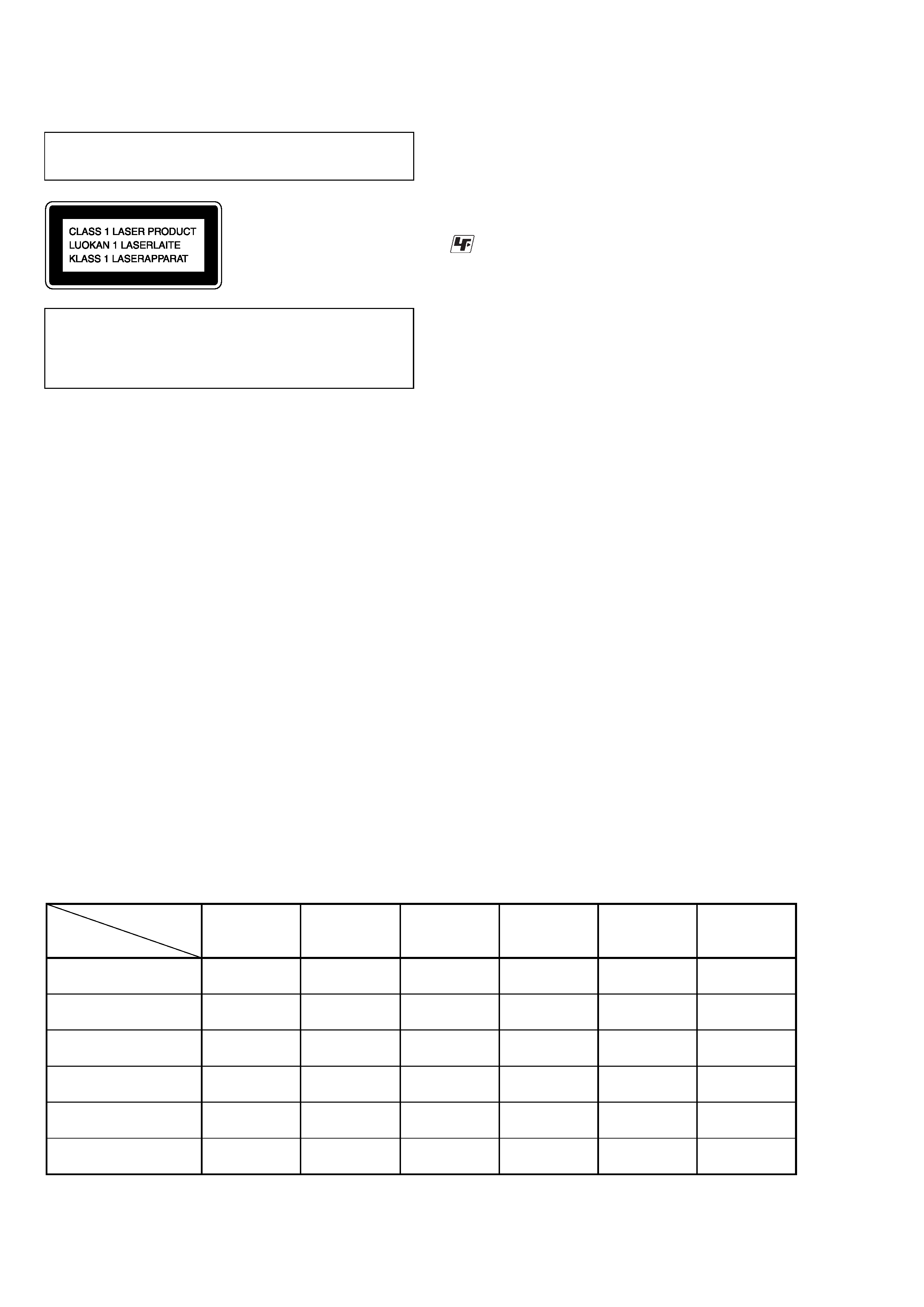
This appliance is classified as a
CLASS 1 LASER product.
The CLASS 1 LASER
PRODUCT MARKING is
located on the rear exterior.
DVD player :
HCD-LF1
DVD player : HCD-LF1
Sub woofer :
SA-WSLF1
Sub woofer : SA-WSLF1
Front speaker :
SS-TSLF1(R)
SS-TSLF1L(L)
Front speaker : SS-TSLF1(R)
SS-TSLF1L(L)
Center speaker :
SS-CTLF1
Center speaker :
SS-CTLF1
Surround speaker :
SS-TSLF1W(R)
SA-TSLF1(L)
Surround speaker : SS-TSLF1W(R)
SA-TSLF1(L)
Remote
commander :
RM-SP320
Remote commander :
RM-SP320
Units required for
operation
check
Unit.
need to
checking
aa
a
aa
a
aa
a
a
a
a
aa
a
a
a
*1
*1
*2
*1 Only the defective unit. *2 Either one of them.
Units with a mark: The units that are required for the system operation check during repair service
However, there can be a case that some units of the system need to not be brought into repair shop depending on the unit. that became defective.
· The units that are required for the system operation check during repair service

3
HCD-LF1
TABLE OF CONTENTS
1.
SERVICING NOTES ................................................ 4
2.
GENERAL ................................................................... 8
3.
DISASSEMBLY
3-1.
Disassembly Flow ........................................................... 10
3-2.
Stand Section ................................................................... 11
3-3.
Cover (MAIN/CDM) ....................................................... 11
3-4.
Chassis Section ................................................................ 12
3-5.
DLED Board .................................................................... 12
3-6.
STBY KEY Board, EJECT KEY Board ......................... 13
3-7.
Mechanism Deck (CDM80AT-DVBU29T) ..................... 13
3-8.
DMB07 Board ................................................................. 14
3-9.
DISPLAY Board .............................................................. 14
3-10. I/O Board ......................................................................... 15
3-11. DVD-POW Board ............................................................ 15
3-12. Chassis (Top) ................................................................... 16
3-13. Lever (Loading R/L) ........................................................ 17
3-14. Disc Stop Lever, Disc Sensor Lever ................................ 18
3-15. DRIVER Board ............................................................... 18
3-16. RF Board ......................................................................... 19
3-17. Optical Pick-up (DBU-3) ................................................ 19
3-18. Base Unit ......................................................................... 20
3-19. Lever (BU Lock) ............................................................. 20
3-20. Close Lever ...................................................................... 21
3-21. DIR Lever, Gear (IDL-B) ................................................ 21
3-22. Gear (IDL-C) ................................................................... 22
4.
TEST MODE ............................................................... 23
5.
ELECTRICAL ADJUSTMENTS .......................... 32
6.
DIAGRAMS
6-1.
Block Diagram
-- RF SERVO Section -- ................... 34
-- DVD DSP Section -- ................................................. 35
-- AUDIO Section -- ...................................................... 36
-- MAIN Section -- ....................................................... 37
6-2.
Printed Wiring Board -- RF Section -- ......................... 38
6-3.
Schematic Diagram -- RF Section -- ........................... 39
6-4.
Printed Wiring Board -- DRIVER Section -- ............... 40
6-5.
Schematic Diagram -- DRIVER Section -- ................. 40
6-6.
Printed Wiring Board -- DMB07 Section (Side A) -- .. 41
6-7.
Printed Wiring Board -- DMB07 Section (Side B) -- .. 42
6-8.
Schematic Diagram -- DMB07 Section (1/10) -- ........ 43
6-9.
Schematic Diagram -- DMB07 Section (2/10) -- ........ 44
6-10. Schematic Diagram -- DMB07 Section (3/10) -- ........ 45
6-11. Schematic Diagram -- DMB07 Section (4/10) -- ........ 46
6-12. Schematic Diagram -- DMB07 Section (5/10) -- ........ 47
6-13. Schematic Diagram -- DMB07 Section (6/10) -- ........ 48
6-14. Schematic Diagram -- DMB07 Section (7/10) -- ........ 49
6-15. Schematic Diagram -- DMB07 Section (8/10) -- ........ 50
6-16. Schematic Diagram -- DMB07 Section (9/10) -- ........ 51
6-17. Schematic Diagram -- DMB07 Section (10/10) -- ...... 52
6-18. Printed Wiring Board -- DVD-POW Section -- ........... 53
6-19. Schematic Diagram -- DVD-POW Section (1/2) -- ..... 54
6-20. Schematic Diagram -- DVD-POW Section (2/2) -- ..... 55
6-21. Printed Wiring Board -- DISPLAY Section -- ............. 56
6-22. Schematic Diagram -- DISPLAY Section -- ................ 57
6-23. Printed Wiring Board -- TOUCH KEY Section -- ....... 58
6-24. Schematic Diagram -- TOUCH KEY Section -- ......... 59
6-25. Printed Wiring Board -- I/O Section -- ........................ 60
6-26. Schematic Diagram -- I/O Section -- ........................... 61
7.
EXPLODED VIEWS
7-1.
Stand Section ................................................................... 84
7-2.
Main Section .................................................................... 85
7-3.
Chassis Section ................................................................ 86
7-4.
Mechanism Deck Section-1 (CDM80AT-DVBU29T) .... 87
7-5.
Mechanism Deck Section-2 (CDM80AT-DVBU29T) .... 88
7-6.
Mechanism Deck Section-3 (CDM80AT-DVBU29T) .... 89
7-7.
Base Unit Section ............................................................ 90
8.
ELECTRICAL PARTS LIST .................................. 91