SERVICE MANUAL
Sony Corporation
Audio Group
Published by Sony Engineering Corporation
US Model
Canadian Model
AEP Model
UK Model
E Model
Australian Model
DVD HOME THEATRE SYSTEM
9-879-673-04
2005J16-1
© 2005.10
Ver. 1.3 2005.10
DAV-DZ100
·DAV-DZ100 is composed of following models.
As service manuals are issued for each component model, please refer to them.
PARTS LIST
COMPONENT MODEL NAME
DAV-DZ100
COMPACT DISC DECK RECEIVER
HCD-DZ100
FRONT SPEAKER
SS-TS31
SURROUND SPEAKER
SS-TS31B
CENTER SPEAKER
SS-CT31
SUB WOOFER
SS-WS31
Part No.
Description
Remark
Part No.
Description
Remark
ACCESSORIES
************
1-479-223-11 COMMANDER, STANDARD (RM-ADU001)
(Including Battery Cover)
(US, CND, EA, MX, SP, KR, AUS, E32)
1-479-226-11 COMMANDER, STANDARD (RM-ADU002)
(Including Battery Cover)
(AEP, UK, RU)
0 1-569-007-11 ADAPTOR, CONVERSION 2P (E32)
1-751-619-43 CORD, CONNECTION (1.5m)(VIDEO)
(US, CND, EA, MX, SP, KR, AUS, E32)
1-754-059-12 ANTENNA, LOOP (AM)
1-754-060-13 ANTENNA (FM)(EXCEPT US, CND)
1-754-147-41 ANTENNA (FM)(US,CND)
1-824-003-11 CORD (WITH CONNECTOR)(RED, 5m)
1-824-003-21 CORD (WITH CONNECTOR)(PURPLE, 5m)
1-824-003-31 CORD (WITH CONNECTOR)(WHITE, 5m)
1-824-003-41 CORD (WITH CONNECTOR)(GRAY, 15m)
1-824-003-51 CORD (WITH CONNECTOR)(BLUE, 15m)
1-824-003-61 (WITH CONNECTOR)(GREEN, 5m)
2-590-880-11 MANUAL, INSTRUCTION (ENGLISH)
(US, CND, EA, SP, AUS, E32)
2-590-880-21 MANUAL, INSTRUCTION
(FRENCH)(CND, EA, SP)
2-590-880-31 MANUAL, INSTRUCTION
(SPANISH)(MX, SP, E32)
2-590-880-41 MANUAL, INSTRUCTION
(TRADITIONAL CHINESE)(SP)
2-590-880-51 MANUAL, INSTRUCTION (KOREAN)(KR)
2-590-880-61 MANUAL, INSTRUCTION (ARABIC)(EA)
2-590-881-11 MANUAL, INSTRUCTION (ENGLISH)(AEP, UK)
2-590-881-21 MANUAL, INSTRUCTION (FRENCH)(AEP)
2-590-881-31 MANUAL, INSTRUCTION (GERMAN)(AEP)
2-590-881-41 MANUAL, INSTRUCTION (DUTCH)(AEP)
2-590-881-51 MANUAL, INSTRUCTION (ITALIAN)(AEP)
2-590-881-61 MANUAL, INSTRUCTION (SPANISH)(AEP)
2-590-881-71 MANUAL, INSTRUCTION (SWEDISH)(AEP)
2-590-881-81 MANUAL, INSTRUCTION (POLISH)(AEP)
2-590-881-91 MANUAL, INSTRUCTION (RUSSIAN)(RU)
4-243-457-01 RUBBER (SPEAKER)
The components identified by
mark 0 or dotted line with mark
0 are critical for safety.
Replace only with part number
specified.
Les composants identifiés par
une marque 0 sont critiques
pour la sécurité.
Ne les remplacer que par une
pièce portant le numéro spécifié.
·Abbreviation
AUS: Australian Model
CND : Cnadian Model
E32 : 110-240V AC area in E model
EA
: Saudi Arabia model
MX : Mexican model
RU
: Russian model
SP
: Singapore model
KR
: Korean model

DAV-DZ100
REVISION HISTORY
Clicking the version allows you to jump to the revised page.
Also, clicking the version at the upper right on the revised page allows you to jump to the next revised
page.
Ver.
Date
Description of Revision
1.0
2005.04
New
1.1
2005.07
Addition of Korean model
1.2
2005.09
Addition of US model
1.3
2005.10
Deletion of package speaker SS-DS11
(SPM-05063)
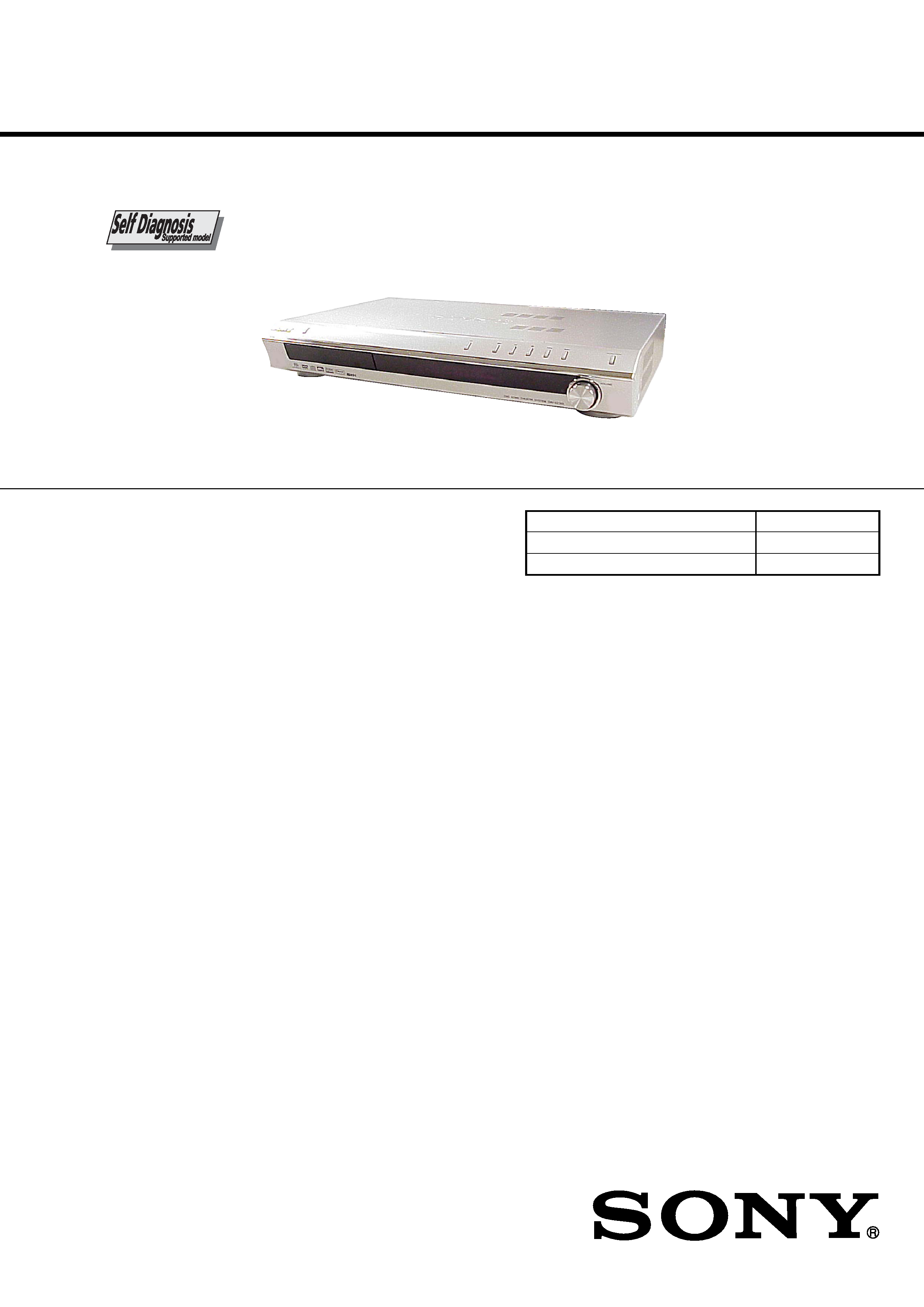
SERVICE MANUAL
Sony Corporation
Home Audio Division
Published by Sony Techno Create Corporation
US Model
Canadian Model
AEP Model
UK Model
E Model
Australian Model
SUPER AUDIO CD/DVD RECEIVER
9-879-674-05
2006C16-1
© 2006.03
Ver. 1.4 2006.03
HCD-DZ100
HCD-DZ100 is the amplifier, DVD/CD and
tuner section in DAV-DZ100.
SPECIFICATIONS
Model Name Using Similar Mechanism
HCD-DZ300
Mechanism Type
CDM85-DVBU102
Optical Pick-up Name
KHM-310CAA/C2NP
This system incorporates with Dolby*1 Digital and Dolby
Pro Logic (II) adaptive matrix surround decoder and the
DTS*2 Digital Surround System.
*1 Manufactured under license from Dolby Laboratories.
"Dolby," "Pro Logic," and the double-D symbol are
trademarks of Dolby Laboratories.
*2 Manufactured under license from Digital Theater
Systems, Inc.
"DTS" and "DTS Digital Surround" are trademarks of
Digital Theater Systems, Inc.
-- Continued on next page --
Amplifier section
North American model:
Surround mode (reference) music power output
Front: 120 W + 120 W
(with SS-TS31)
Center*: 120 W
(with SS-CT31)
Surround*: 120 W + 120
W
(with SS-TS31B)
Subwoofer*: 120 W
(with SS-WS31)
Other models:
Stereo mode (rated)
55 W + 55 W (3 ohms at 1
kHz, DIN)
Surround mode (reference) music power output
Front: 120 W + 120 W
(with SS-TS31)
Center*: 120 W
(with SS-CT31)
Surround*: 120 W + 120
W
(with SS-TS31B)
Subwoofer*: 120 W
(with SS-WS31)
*Depending on the sound field settings and the source,
there may be no sound output.
Inputs
VIDEO/SAT (AUDIO IN) Sensitivity: 250/450 mV
Impedance: 50 kilohms
DVD system
Laser
Semiconductor laser
(DVD:
= 650 nm)
(CD:
= 790 nm)
Emission duration:
continuous
Signal format system
North American, Latin, and Mexican models:
NTSC
Other models:
NTSC/PAL
Frequency response (at 2 CH STEREO mode)
DVD (PCM): 2 Hz to 22
kHz (
±1.0 dB)
CD: 2 Hz to 20 kHz (
±1.0
dB)
(EXCEPT AEP, UK, RU)
TV
Sensitivity: 450 mV
Impedance: 50 kilohms
(AEP, UK, RU)
Tuner section
System
PLL quartz-locked digital
synthesizer system
AUDIO POWER SPECIFICATIONS
for the US model
POWER OUTPUT AND
TOTAL HARMONIC
DISTORTION:
With 3 ohm loads, both
channels driven, from
200 20,000 Hz; rated
55 watts per channel
minimum RMS power,
with no more than 0.7 %
total harmonic distortion
from 250 milli watts to
rated output.
FM tuner section
Tuning range
North American model:
87.5 108.0 MHz
(100 kHz step)
I
Other models:
87.5 108.0 MHz
(50 kHz step)
Antenna (aerial)
FM wire antenna (aerial)
Antenna (aerial) terminals 75 ohms, unbalanced
ntermediate frequency
10.7 MHz
AM tuner section
Tuning range
530 1,710 kHz (with the
interval set at 10 kHz)
531 1,710 kHz (with the
interval set at 9 kHz)
North American, Latin, and Mexican models:
2
HCD-DZ100
Ver. 1.2
CAUTION
Use of controls or adjustments or performance of procedures
other than those specified herein may result in hazardous radiation
exposure.
UNLEADED SOLDER
Boards requiring use of unleaded solder are printed with the lead-
free mark (LF) indicating the solder contains no lead.
(Caution: Some printed circuit boards may not come printed with
the lead free mark due to their particular size)
: LEAD FREE MARK
Unleaded solder has the following characteristics.
· Unleaded solder melts at a temperature about 40 °C higher
than ordinary solder.
Ordinary soldering irons can be used but the iron tip has to be
applied to the solder joint for a slightly longer time.
Soldering irons using a temperature regulator should be set to
about 350
°C.
Caution: The printed pattern (copper foil) may peel away if
the heated tip is applied for too long, so be careful!
· Strong viscosity
Unleaded solder is more viscou-s (sticky, less prone to flow)
than ordinary solder so use caution not to let solder bridges
occur such as on IC pins, etc.
· Usable with ordinary solder
It is best to use only unleaded solder but unleaded solder may
also be added to ordinary solder.
Notes on chip component replacement
· Never reuse a disconnected chip component.
· Notice that the minus side of a tantalum capacitor may be
damaged by heat.
Flexible Circuit Board Repairing
· Keep the temperature of the soldering iron around 270 °C
during repairing.
· Do not touch the soldering iron on the same conductor of the
circuit board (within 3 times).
· Be careful not to apply force on the conductor when soldering
or unsoldering.
Laser component in this product is capable of emitting radiation
exceeding the limit for Class 1.
This appliance is classified as
a CLASS 1 LASER product.
The
CLASS
1
LASER
PRODUCT MARKING is
located on the rear exterior.
Video section
Outputs
Video: 1 Vp-p 75 ohms
S video:
Y: 1 Vp-p 75 ohms
C: 0.286 Vp-p 75 ohms
COMPONENT:
Y: 1 Vp-p 75 ohms
PB/CB, PR/CR: 0.7 Vp-p
75 ohms
Video: 1 Vp-p 75 ohms
R/G/B: 0.7 Vp-p 75 ohms
(EXCEPT AEP, UK, RU)
(AEP, UK, RU)
Antenna (aerial)
AM loop antenna (aerial)
Intermediate frequency
450 kHz
Middle eastern models:
531 1,602 kHz (with the
interval set at 9 kHz)
Other models:
530 1,710 kHz (with the
interval set at 10 kHz)
531 1,602 kHz (with the
interval set at 9 kHz)
General
Power requirements
North American and Mexican models:
120 V AC, 60 Hz
Central/South American models:
110 240 V AC, 50/60 Hz
Taiwan model:
12
Korean model:
220 V AC, 60 Hz
0 V AC, 50/60 Hz
Other models:
220 240 V AC, 50/60 Hz
Power consumption
On: 135 W
Standby: 0.3 W (at the
Power Saving mode)
Dimensions (approx.)
430
70
295 mm
(17
27/8
115/8 inches)
(w/h/d) incl. projecting
parts
Mass (approx.)
3.6 kg (7 lb 15 oz)
Design and specifications are subject to change
without notice.
×
×
××
MODEL IDENTIFICATION
Rear Panel
Model
Part No.
AEP, UK models
2-588-951-0[]
RU model
2-588-951-1[]
EA model
2-588-951-2[]
SP model
2-588-951-3[]
CND model
2-588-951-4[]
AUS model
2-588-951-5[]
KR model
2-588-951-6[]
E32 model
2-588-951-7[]
MX model
2-588-951-9[]
US model
2-634-883-1[]
·Abbreviation
AUS: Australian model
CND
: Canadian model
E32
: 110-240V AC area
in E model
EA
: Saudi Arabia model
KR
: Korean model
MX
: Mexican model
RU
: Russian model
SP
: Singapore model
Parts No.
3
HCD-DZ100
TABLE OF CONTENTS
1.
SERVICING NOTE ................................................... 4
2.
GENERAL ................................................................... 6
3.
DISASSEMBLY
3-1.
Disassembly Flow ........................................................... 10
3-2.
Case, Front Panel Assy .................................................... 11
3-3.
FL Board .......................................................................... 12
3-4.
KEY Board, STBY Board ............................................... 12
3-5.
I/O Board, DC Fan .......................................................... 13
3-6.
DMB11 Board ................................................................. 13
3-7.
MAIN Board .................................................................... 14
3-8.
DVD Mechanism Deck (CDM85-DVBU102) ................ 15
3-9.
Tray .................................................................................. 15
3-10. Belt, MS-203 Board ........................................................ 16
3-11. Optical Pick-up (KHM-310CAA/C2NP) ........................ 17
4.
TEST MODE ............................................................... 18
5.
DIAGRAMS
5-1.
Block Diagram RF/SERVO Section ......................... 24
5-2.
Block Diagram VIDEO Section ............................... 25
5-3.
Block Diagram AMP Section ................................... 26
5-4.
Block Diagram AUDIO Section ............................... 27
5-5.
Block Diagram POWER Section .............................. 28
5-6.
Printed Wiring Board DMB11 Board (Side A) ........ 29
5-7.
Printed Wiring Board DMB11 Board (Side B) ........ 30
5-8.
Schematic Diagram DMB11 Board (1/5) ................. 31
5-9.
Schematic Diagram DMB11 Board (2/5) ................. 32
5-10. Schematic Diagram DMB11 Board (3/5) ................. 33
5-11. Schematic Diagram DMB11 Board (4/5) ................. 34
5-12. Schematic Diagram DMB11 Board (5/5) ................. 35
5-13. Printed Wiring Board MAIN Section (Side A) ........ 36
5-14. Printed Wiring Board MAIN Board (Side B) ........... 37
5-15. Schematic Diagram MAIN Board (1/7) ................... 38
5-16. Schematic Diagram MAIN Board (2/7) ................... 39
5-17. Schematic Diagram MAIN Board (3/7) ................... 40
5-18. Schematic Diagram MAIN Board (4/7) ................... 41
5-19. Schematic Diagram MAIN Board (5/7) ................... 42
5-20. Schematic Diagram MAIN Board (6/7) ................... 43
5-21. Schematic Diagram MAIN Board (7/7) ................... 44
5-22. Printed Wiring Board PANEL Section ..................... 45
5-23. Schematic Diagram PANEL Section ....................... 46
5-24. Printed Wiring Board I/O Board .............................. 47
5-25. Schematic Diagram I/O Board (1/2) ........................ 48
5-26. Schematic Diagram I/O Board (2/2) ........................ 49
5-27. Printed Wiring Board MS-203 Board ....................... 50
5-28. Schematic Diagram MS-203 Board ......................... 50
6.
EXPLODED VIEWS
6-1.
Overall Section ................................................................ 63
6-2.
Front Panel Section ......................................................... 64
6-3.
Chassis Section ................................................................ 65
6-4.
DVD Mechanism Deck Section (CDM85-DVBU102) ... 66
7.
ELECTRICAL PARTS LIST .................................. 67
SAFETY-RELATED COMPONENT WARNING!!
COMPONENTS IDENTIFIED BY MARK 0 OR DOTTED LINE
WITH MARK 0 ON THE SCHEMATIC DIAGRAMS AND IN
THE PARTS LIST ARE CRITICAL TO SAFE OPERATION.
REPLACE THESE COMPONENTS WITH SONY PARTS WHOSE
PART NUMBERS APPEAR AS SHOWN IN THIS MANUAL OR
IN SUPPLEMENTS PUBLISHED BY SONY.
ATTENTION AU COMPOSANT AYANT RAPPORT
À LA SÉCURITÉ!
LES COMPOSANTS IDENTIFIÉS PAR UNE MARQUE 0 SUR
LES DIAGRAMMES SCHÉMATIQUES ET LA LISTE DES
PIÈCES
SONT
CRITIQUES
POUR
LA
SÉCURITÉ
DE
FONCTIONNEMENT. NE REMPLACER CES COM- POSANTS
QUE PAR DES PIÈCES SONY DONT LES NUMÉROS SONT
DONNÉS DANS CE MANUEL OU DANS LES SUPPLÉMENTS
PUBLIÉS PAR SONY.
SAFETY CHECK-OUT
After correcting the original service problem, perform the following
safety check before releasing the set to the customer:
Check the antenna terminals, metal trim, "metallized" knobs, screws,
and all other exposed metal parts for AC leakage.
Check leakage as described below.
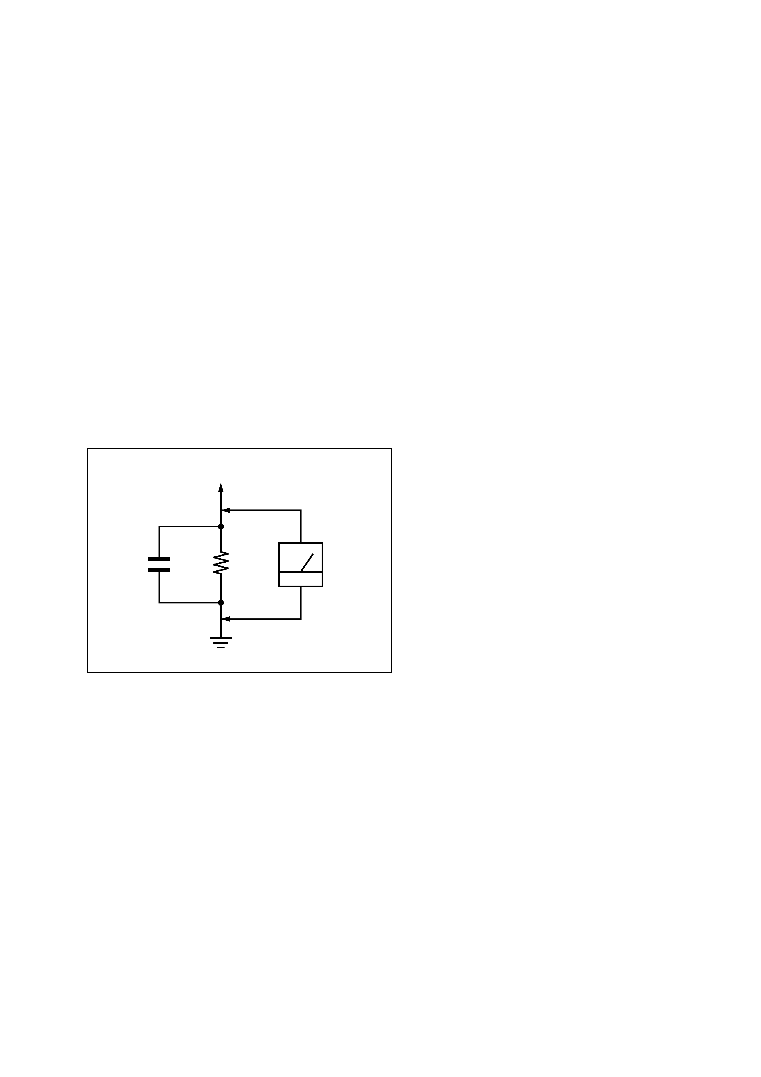
LEAKAGE TEST
The AC leakage from any exposed metal part to earth ground and
from all exposed metal parts to any exposed metal part having a
return to chassis, must not exceed 0.5 mA (500 microamperes.).
Leakage current can be measured by any one of three methods.
1. A commercial leakage tester, such as the Simpson 229 or RCA
WT-540A. Follow the manufacturers' instructions to use these
instruments.
2. A battery-operated AC milliammeter. The Data Precision 245
digital multimeter is suitable for this job.
3. Measuring the voltage drop across a resistor by means of a
VOM or battery-operated AC voltmeter. The "limit" indication
is 0.75 V, so analog meters must have an accurate low-voltage
scale. The Simpson 250 and Sanwa SH-63Trd are examples
of a passive VOM that is suitable. Nearly all battery operated
digital multimeters that have a 2 V AC range are suitable. (See
Fig. A)
1.5 k
0.15
µF
AC
voltmeter
(0.75 V)
To Exposed Metal
Parts on Set
Earth Ground
Fig. A.
Using an AC voltmeter to check AC leakage.
Ver. 1.2