SERVICE MANUAL
9-874-058-01
Sony Corporation
2002G0500-1
Home Audio Company
C
2002.07
Published by Sony Engineering Corporation.
Ver 1.0 2002.07
COMPACT AV SYSTEM
DAV-C770
DAV-C990
SACD/DVD RECEIVER
HCD-C770
HCD-C990
FRONT SPEAKER
SS-TS503
SS-TS551
CENTER SPEAKER
SS-TS503
SS-CT551
REAR SPEAKER
SS-TS503
SS-TS551
SUB WOOFER
SS-WS503
SS-WS551
PACKAGE SPEAKER
SS-WT503
SS-C990
US Model
Canadian Model
DAV-C770/C990
AEP Model
Australian Model
DAV-C770
·DAV-C770/C990 are composed of following models.
As service manuals are issued for each component model, please refer to them.
COMPONENT MODEL NAME
1-477-372-11 COMMANDER, STANDARD (RM-SS990)
1-754-060-13 ANTENNA (FM) (C770: AEP, Australian)
1-754-147-11 ANTENNA (FM) (C770: US, Canadian/C990)
1-754-149-11 LOOP ANT (AM)
1-769-108-11 CORD, CONNECTION (VIDEO CORD)
1-824-622-11 CORD (WITH CONNECTOR) (RED)
(for FRONT R SPEAKER)
1-824-622-21 CORD (WITH CONNECTOR) (PURPLE) (for SUB WOOFER)
1-824-622-31 CORD (WITH CONNECTOR) (WHITE)
(for FRONT L SPEAKER)
1-824-622-41 CORD (WITH CONNECTOR) (GRAY)
(for REAR R SPEAKER)
1-824-622-51 CORD (WITH CONNECTOR) (BLUE)
(for REAR L SPEAKER)
1-824-622-61 CORD (WITH CONNECTOR) (GREEN)
(for CENTER SPEAKER)
1-824-180-11 CORD, CONNECTION (21PIN ADAPTER) (AEP)
4-241-068-11 MANUAL, INSTRUCTION (ENGLISH) (C770)
4-241-068-21 MANUAL, INSTRUCTION (FRENCH) (C770: Canadian, AEP)
4-241-068-31 MANUAL, INSTRUCTION (GERMAN, SPANISH, DUTCH,
SWEDISH, ITALIAN, POLISH) (C770: AEP)
4-241-068-41 MANUAL, INSTRUCTION (DANISH, FINNISH,
PORTUGUESE) (C770: AEP)
4-241-068-51 MANUAL, INSTRUCTION (GREEK) (C770: AEP)
4-241-071-11 MANUAL, INSTRUCTION (ENGLISH) (C990)
4-241-071-21 MANUAL, INSTRUCTION (FRENCH) (C990: Canadian)
4-243-416-01 BATTERY COVER (for RM-SS990)
4-243-457-01 RUBBER (SPEAKER) (for SPEAKER)
PARTS LIST
Part No.
Description
Remark
DAV-C770/C990
SPECIFICATIONS
General
Power requirements
North American model:
120 V AC, 60 Hz
European model:
230 V AC, 50/60 Hz
Australian model:
220 240 V AC, 50/60 Hz
Power consumption
135
140 W (120 V AC) (DAV-C990)
W (120 V AC) 135 W (230 V AC) (DAV-C770)
1 W (120 V AC) 2 W (230 V AC) (at the Power Saving Mode)
Dimensions (approx.)
355
× 70 × 335 mm (14 × 2 7/8 × 13 1/4 inches: DAV-C770)
(14
× 2 7/8 × 15 inches: DAV-C990) (w/h/d) incl. projecting parts
Mass (approx.)
4.4 kg (9 lb 12 oz)
Operating temperature
5°C to 35°C (41°F to 95°F)
Operating humidity
5 % to 90 %
Supplied accessories
Design and specifications are subject to change without notice.
· Speakers (5)
· Subwoofer (1)
· AM loop antenna (1)
· FM wire antenna (1)
· Speaker cords (5m
× 4, 15m × 2) (17ft. × 4, 50ft. × 2)
· Video cord (1)
· Remote Commander (remote) RM-SS990 (1)
· R6 (size AA) batteries (2)
· Foot pads (20)
· Speakers-connection and Installation (card) (1)
· 21-pin Adapter (1) (Only for the European models)
2
DAV-C770/C990
REVISION HISTORY
Clicking the version allows you to jump to the revised page.
Also, clicking the version at the upper right on the revised page allows you to jump to the next revised
page.
Ver.
Date
Description of Revision
1.0
2002.07
New
SERVICE MANUAL
SACD/DVD RECEIVER
US Model
Canadian Model
HCD-C770/C990
AEP Model
Australian Model
HCD-C770
HCD-C770/C990
Ver 1.6 2004.09
9-874-059-07
Sony Corporation
2004I05-1
Audio Group
© 2004.09
Published by Sony Engineering Corporation
SPECIFICATIONS
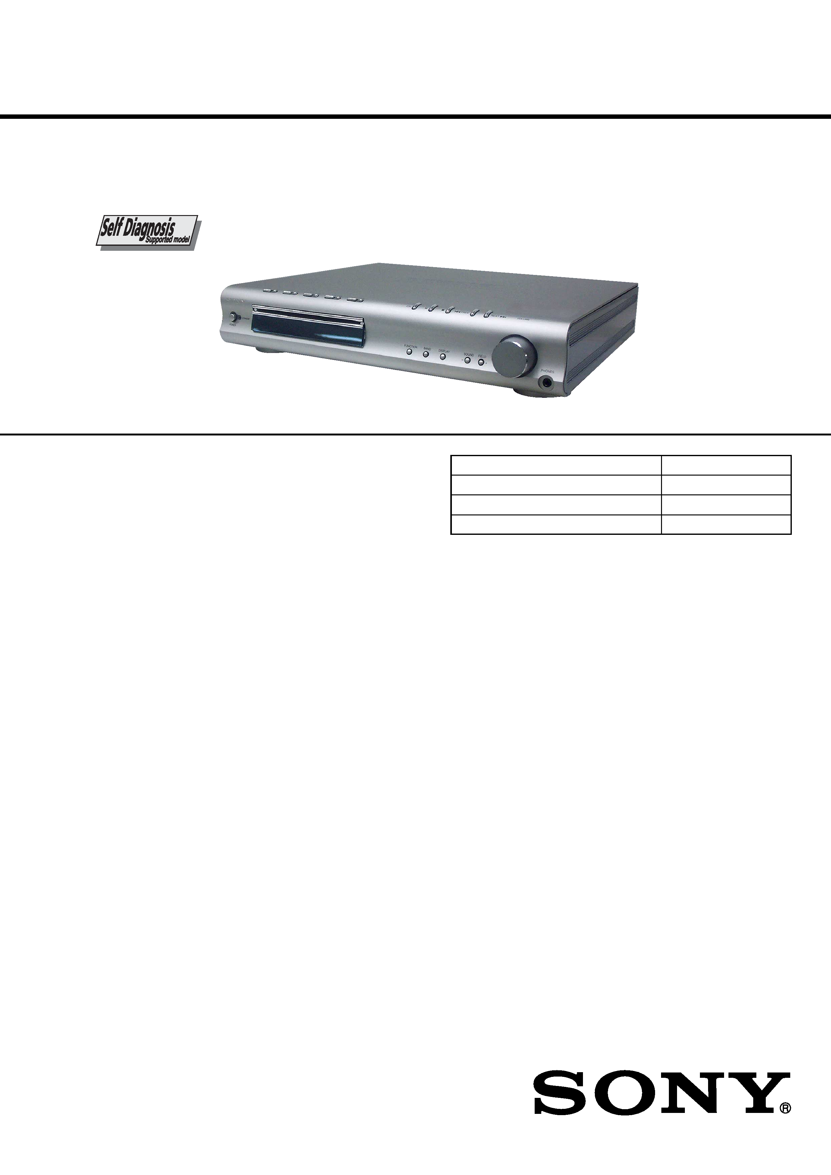
HCD-C770/C990 is the amplifier, DVD/CD
player and tuner section in DAV-C770/C990.
Model Name Using Similar Mechanism
NEW
Mechanism Type
CDM69-DVBU16
Base Unit Name
DVBU16
Optical Traverse Unit Name
DBU-1
AUDIO POWER SPECIFICATIONS (C770: US model)
POWER OUTPUT AND TOTAL HARMONIC DISTORTION:
With 3 ohm loads, both channels driven, from 150 10,000 Hz; rated
70 watts per channel minimum RMS power, with no more than 1 %
total harmonic distortion from 250 milliwatts to rated output.
Amplifier section
Stereo mode (C770)
90 W + 90 W (3 ohms at 1 kHz, THD 10 %)
Surround mode (C770)
Front: 90 W + 90 W
Center*: 90 W
Rear*: 90 W + 90 W (3 ohms at 1 kHz, THD 10 %)
Subwoofer*: 100 W (3 ohms at 100 Hz, THD 10 %)
* Depending on the sound field settings and the source, there may be no sound output.
Inputs (Analog)
VIDEO 1, 2:
Sensitivity: 150 mV
Impedance: 50 kilohms
Inputs (Digital)
VIDEO 2 (optical):
Sensitivity:
Outputs (Analog)
VIDEO 1 (AUDIO OUT):
Voltage: 2 V
Impedance: 1 kilohms
PHONES:
Accepts low- and high-impedance headphones
AUDIO POWER SPECIFICATIONS (C990: US model)
POWER OUTPUT AND TOTAL HARMONIC DISTORTION:
With 3 ohm loads, both channels driven, from 150 10,000 Hz; rated
75 watts per channel minimum RMS power, with no more than 1 %
total harmonic distortion from 250 milliwatts to rated output.
Stereo mode (C990)
100 W + 100 W (3 ohms at 1 kHz, THD 10 %)
Surround mode (C990)
Front: 100 W + 100 W
Center*: 100 W
Rear*: 100 W + 100 W (3 ohms at 1 kHz, THD 10 %)
Subwoofer*: 100 W (3 ohms at 100 Hz, THD 10 %)
Continued on next page
Photo: HCD-C770
HCD-C770/C990
2
Note: Refer to the "5. TEST MODE" (page 22) for another self-diagnosis
function.
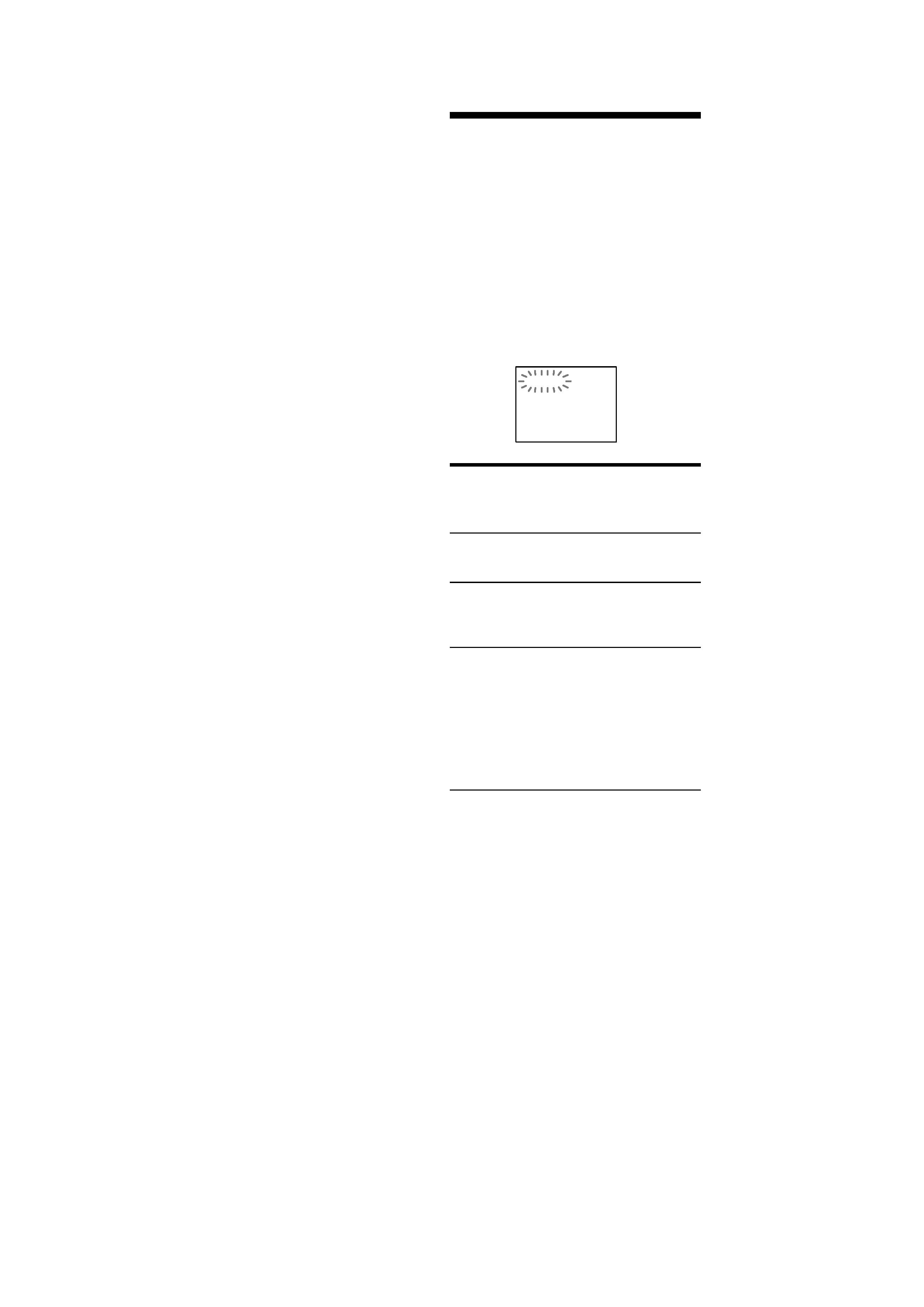
Self-diagnosis Function
(When letters/numbers appear in the
display)
When the self-diagnosis function is
activated to prevent the system from
malfunctioning. In this case a five-character
service number (e.g., C 13 00) with a
combination of a letter and digits appears on
the screen and the front panel display. Refer
to the following table.
First three
characters of
the service
number
C 13
C 31
E XX
(xx is a number)
Cause and/or Corrective
Action
The disc is dirty.
, Clean the disc with a soft
cloth.
The disc is not inserted
correctly.
, Re-insert the disc
correctly.
To prevent a malfunction, the
system has performed the self-
diagnosis function.
, Contact your nearest Sony
dealer or local authorized
Sony service facility and
give the 5-character
service number.
Example: E 61 10
C:13:00
SELF DIAGNOSIS FUNCTION
Super Audio CD/DVD system
Laser
Semiconductor laser
(Super Audio CD/DVD:
= 650 nm)
(CD:
= 780 nm)
Emission duration: continuous
Signal format system
NTSC or NTSC/PAL
Frequency response (at 2 CH STEREO mode)
DVD (PCM): 2 Hz to 22 kHz (
±1.0 dB)
CD: 2 Hz to 20 kHz (
±1.0 dB)
Signal-to-noise ratio
More than 80 dB (VIDEO 1 (AUDIO) connectors only)
Harmonic distortion
Less than 0.03 %
FM tuner section
System
PLL quartz-locked digital synthesizer system
Tuning range
North American model:
87.5 108.0 MHz (100 kHz step)
Other models:
87.5 108.0 MHz (50 kHz step)
Antenna
FM wire antenna
Antenna terminals
75 ohms, unbalanced
Intermediate frequency
10.7 MHz
AM tuner section
System
PLL quartz-locked digital synthesizer system
Tuning range
North American model:
530 1,710 kHz (with the interval set at 10 kHz)
531 1,710 kHz (with the interval set at 9 kHz)
European model:
531 1,602 kHz (with the interval set at 9 kHz)
Other models:
531 1,602 kHz (with the interval set at 9 kHz)
530 1,710 kHz (with the interval set at 10 kHz)
Antenna
Loop antenna
Intermediate frequency
450 kHz
Video section
Inputs
Video: 1 Vp-p 75 ohms
Outputs
Video: 1 Vp-p 75 ohms
S video:
Y: 1 Vp-p 75 ohms
C: 0.286 Vp-p 75 ohms
COMPONENT:
Y: 1 Vp-p 75 ohms
PB/CB, PR/CR: 0.7 Vp-p 75 ohms
General
Power requirements
North American model:
120 V AC, 60 Hz
European model:
230 V AC, 50/60 Hz
Australian model:
220 240 V AC, 50/60 Hz
Power consumption (C770)
135 W (120 V AC) 135 W (230 V AC)
1 W (120 V AC) 2 W (230 V AC)
Dimensions (approx.)
× 70 × 335 mm (14 × 2
7/8 × 13 1/4 inches) (w/h/d)
incl. projecting parts
Mass (approx.)
4.4 kg (9 lb 12 oz)
Operating temperature
5°C to 35°C (41°F to 95°F)
Operating humidity
5 % to 90 %
Design and specifications are subject to change without notice.
355
Power consumption (C990)
140 W (120 V AC)
1 W (120 V AC) (at the Power Saving Mode)
(at the Power Saving Mode)
HCD-C770/C990
3
Notes on chip component replacement
·Never reuse a disconnected chip component.
· Notice that the minus side of a tantalum capacitor may be dam-
aged by heat.
Flexible Circuit Board Repairing
·Keep the temperature of the soldering iron around 270 °C dur-
ing repairing.
· Do not touch the soldering iron on the same conductor of the
circuit board (within 3 times).
· Be careful not to apply force on the conductor when soldering
or unsoldering.
CAUTION
Use of controls or adjustments or performance of procedures
other than those specified herein may result in hazardous ra-
diation exposure.
ATTENTION AU COMPOSANT AYANT RAPPORT
À LA SÉCURITÉ!
LES COMPOSANTS IDENTIFIÉS PAR UNE MARQUE 0
SUR LES DIAGRAMMES SCHÉMATIQUES ET LA LISTE
DES PIÈCES SONT CRITIQUES POUR LA SÉCURITÉ
DE FONCTIONNEMENT. NE REMPLACER CES COM-
POSANTS QUE PAR DES PIÈCES SONY DONT LES
NUMÉROS SONT DONNÉS DANS CE MANUEL OU
DANS LES SUPPLÉMENTS PUBLIÉS PAR SONY.
SAFETY-RELATED COMPONENT WARNING!!
COMPONENTS IDENTIFIED BY MARK 0 OR DOTTED
LINE WITH MARK 0 ON THE SCHEMATIC DIAGRAMS
AND IN THE PARTS LIST ARE CRITICAL TO SAFE
OPERATION. REPLACE THESE COMPONENTS WITH
SONY PARTS WHOSE PART NUMBERS APPEAR AS
SHOWN IN THIS MANUAL OR IN SUPPLEMENTS PUB-
LISHED BY SONY.
This appliance is classified as a
CLASS 1 LASER product. The label
is located on the bottom exterior.
This label is located on the bottom
exterior.
SAFETY CHECK-OUT
After correcting the original service problem, perform the follow-
ing safety check before releasing the set to the customer:
Check the antenna terminals, metal trim, "metallized" knobs,
screws, and all other exposed metal parts for AC leakage.
Check leakage as described below.
LEAKAGE TEST
The AC leakage from any exposed metal part to earth ground and
from all exposed metal parts to any exposed metal part having a
return to chassis, must not exceed 0.5 mA (500 microamperes.).
Leakage current can be measured by any one of three methods.
1. A commercial leakage tester, such as the Simpson 229 or RCA
WT-540A. Follow the manufacturers' instructions to use these
instruments.
2. A battery-operated AC milliammeter. The Data Precision 245
digital multimeter is suitable for this job.
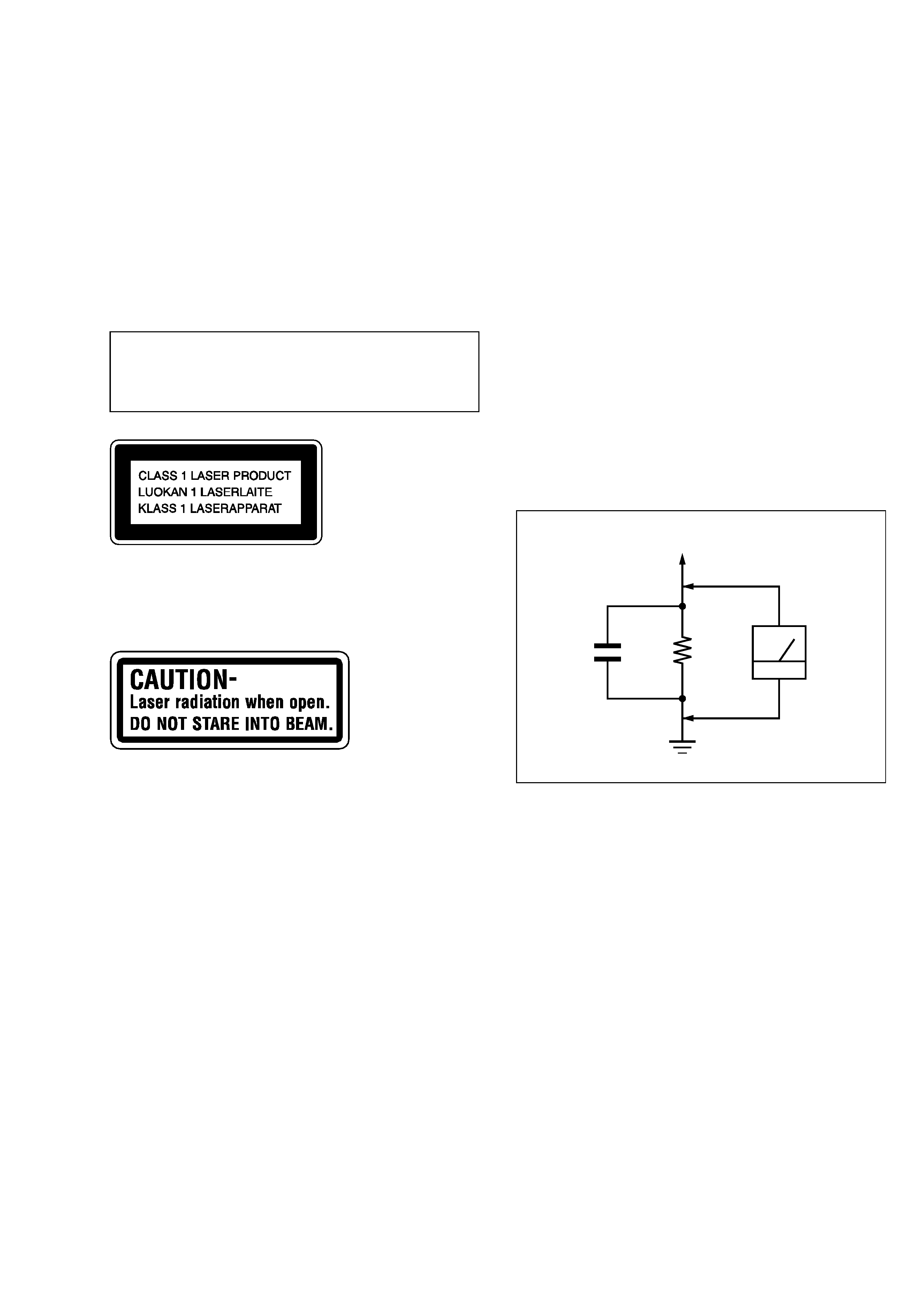
3. Measuring the voltage drop across a resistor by means of a VOM
or battery-operated AC voltmeter. The "limit" indication is 0.75
V, so analog meters must have an accurate low-voltage scale.
The Simpson 250 and Sanwa SH-63Trd are examples of a pas-
sive VOM that is suitable. Nearly all battery operated digital
multimeters that have a 2 V AC range are suitable. (See Fig. A)
Fig. A.
Using an AC voltmeter to check AC leakage.
1.5 k
0.15 µF
AC
voltmeter
(0.75 V)
To Exposed Metal
Parts on Set
Earth Ground