DAV-C450
US Model
Canadian Model
E Model
Australian Model
SERVICE MANUAL
COMPACT AV SYSTEM
Sony Corporation
Home Audio Group
Published by Sony Engineering Corporation
9-873-995-03
2005G16-1
© 2005.07
·DAV-C450 is composed of following model.
As for the service manual, it is issued for each component
model, then, please refer to it.
Ver. 1.2 2005.07
COMPONENT MODEL NAME
·Abbreviation
CND
: Canadian model.
E12
: 220 240 V AC area in E model.
E32
: 110 240 V AC area in E model.
EA
: Saudi Arabia model.
MX
: Mexican model.
MY
: Malaysia model.
SP
: Singapore model.
PARTS LIST
The components identified by
mark 0 or dotted line with mark
0 are critical for safety.
Replace only with part number
specified.
Les composants identifiés par
une marque 0 sont critiques
pour la sécurité.
Ne les remplacer que par une
pièce portant le numéro spécifié.
Part No.
Description
Remarks
ACCESSORIES
************
1-477-335-11 REMOTE COMMANDER (RM-SS450)
0 1-569-008-21 ADAPTOR, CONVERSION 2P (E32,MY,SP,EA)
1-754-060-12 ANTENNA (FM) (EXCEPT US,CND)
1-754-147-11 ANTENNA (FM) (F TYPE) (US,CND)
1-754-149-11 LOOP ANT (AM)
1-769-108-12 CORD, CONNECTION (VIDEO CORD)
1-823-352-11 CORD (WITH CONNECTOR) (5m) (RED)
1-823-352-21 CORD (WITH CONNECTOR) (5m) (PURPLE)
1-823-352-31 CORD (WITH CONNECTOR) (5m) (WHITE)
1-823-352-41 CORD (WITH CONNECTOR) (15m) (GRAY)
1-823-352-51 CORD (WITH CONNECTOR) (15m) (BLUE)
1-823-352-61 CORD (WITH CONNECTOR) (5m) (GREEN)
4-228-654-01 CUSHION (FOR SS-TS502/WS502)
4-240-154-11 MANUAL, INSTRUCTION (ENGLISH)
4-240-154-21 MANUAL, INSTRUCTION (FRENCH) (CND,E12,EA)
4-240-154-31 MANUAL, INSTRUCTION (SPANISH) (E32,MX)
4-240-154-41 MANUAL, INSTRUCTION (ARABIC) (EA)
4-240-154-51 MANUAL, INSTRUCTION (CHINESE) (MY,SP)
4-240-873-02 COVER,BATTERY (FOR RM-SS450)
DAV-C450
SS-WT502
SS-TS502
(FRONT, CENTER, REAR
SPEAKER SYSTEM)
SS-WS502
(SUBWOOFER SPEAKER
SYSTEM)
HCD-C450
(COMPACT DISC DECK
RECEIVER SYSTEM)
DAV-C450
REVISION HISTORY
Clicking the version allows you to jump to the revised page.
Also, clicking the version at the upper right on the revised page allows you to jump to the next revised
page.
Ver.
Date
Description of Revision
1.0
2002.04
New
1.1
2002.08
Part number of cord (with connector) is corrected
(SPM-02064)
1.2
2005.07
Mark of the color of the speaker codes are corrected
(SPM-05045)
HCD-C450
US Model
Canadian Model
E Model
Australian Model
SERVICE MANUAL
COMPACT AV SYSTEM
HCD-C450 is the amplifier, DVD/CD and tuner
section in DAV-C450.
SPECIFICATIONS
Ver 1.6 2004.08
Model Name Using Similar Mechanism
NEW
Mechanism Type
CDM53K-DVBU7
Base Unit Name
DVBU7
Optical Pick-up Name
KHM-240AAA
Sony Corporation
Audio Group
Published by Sony Engineering Corporation
9-874-002-07
2004H16-1
© 2004.08
AUDIO POWER SPECIFICATIONS
POWER OUTPUT AND TOTAL HARMONIC DISTORTION:
With 3 ohms loads, both channels driven, from 120 10,000 Hz; rated
80 watts per channel minimum RMS power, with no more than 10 %
total harmonic distortion from 250 milliwatts to rated output.
Amplifier section
Stereo mode
North American and Mexican models:
80 W + 80 W (3 ohms at 1 kHz, THD 10 %)
Other models:
70 W + 70 W (4 ohms at 1 kHz, THD 10 %)
Surround mode
North American and Mexican models:
Front: 80 W + 80 W
Center*: 80 W
Rear*: 80 W + 80 W (3 ohms at 1 kHz, THD 10 %)
Subwoofer*: 100 W (3 ohms at 100 Hz, THD 10 %)
Other models:
Front: 70 W + 70 W
Center*: 70 W
Rear*: 70 W + 70 W (4 ohms at 1 kHz, THD 10 %)
Subwoofer*: 100 W (3 ohms at 100 Hz, THD 10 %)
* Depending on the sound field settings and the source, there may be no sound output.
Inputs (Analog)
AUDIO 1, 2:
Sensitivity: 150 mV
Impedance: 50 kilohms
Inputs (Digital)
AUDIO 2 (optical):
Sensitivity:
Outputs (Analog)
AUDIO 1 (AUDIO OUT):
Voltage: 2 V
Impedance: 1 kilohms
PHONES:
Accepts low and high-impedance headphones
Super Audio CD/DVD system
Laser
Semiconductor laser
(Super Audio CD/DVD:
= 650 nm)
(CD:
= 780 nm)
Emission duration: continuous
Signal format system
NTSC or NTSC/PAL
Frequency response (at 2 CH STEREO mode)
DVD (PCM): 2 Hz to 22 kHz (
±1.0 dB)
CD: 2 Hz to 20 kHz (
±1.0 dB)
Signal-to-noise ratio
More than 80 dB (AUDIO 1 (AUDIO) connectors only)
Harmonic distortion
Less than 0.03 %
FM tuner section
System
PLL quartz-locked digital synthesizer system
North American model:
87.5 108.0 MHz (100 kHz step)
Other models:
87.5 108.0 MHz (50 kHz step)
Antenna
FM wire antenna
Antenna terminals
75 ohms, unbalanced
AM tuner section
System
Tuner section:
PLL quartz-locked digital synthesizer system
Tuning range
North American model:
530 1,710 kHz (with the interval set at 10 kHz)
531 1,710 kHz (with the interval set at 9 kHz)
Middle Eastern, and Philipinne models:
531 1,602 kHz (with the interval set at 9 kHz)
Other models:
531 1,602 kHz (with the interval set at 9 kHz)
530 1,710 kHz (with the interval set at 10 kHz)
Antenna
Loop antenna
Video section
Outputs
VIDEO: 1 Vp-p 75 ohms
S-VIDEO: Y: 1 Vp-p 75 ohms
C: 0.286 Vp-p 75 ohms
COMPONENT: Y: 1 Vp-p 75 ohms
PB/CB, PR/CR: 0.7 Vp-p 75 ohms
General
Power requirements
North American model:
120 V AC, 60 Hz
Australian and Asian models:
220 240 V AC, 50/60 Hz
Middle Eastern, and Philippine models:
110 240 V/ 220 240 V AC, 50/60 Hz
Power consumption
120 W (120 V AC), 120 W (230 V AC)
Dimensions (approx.)
355
× 100 × 394 mm (14 × 4 × 15 5/8 inches) (w/h/d) incl. projecting parts
Mass (approx.)
5.5 kg (12 lb 3 oz)
Operating temperature
5°C to 35°C (41°F to 95°F)
Operating humidity
5 % to 90 %
Design and specifications are subject to change without notice.
2
HCD-C450
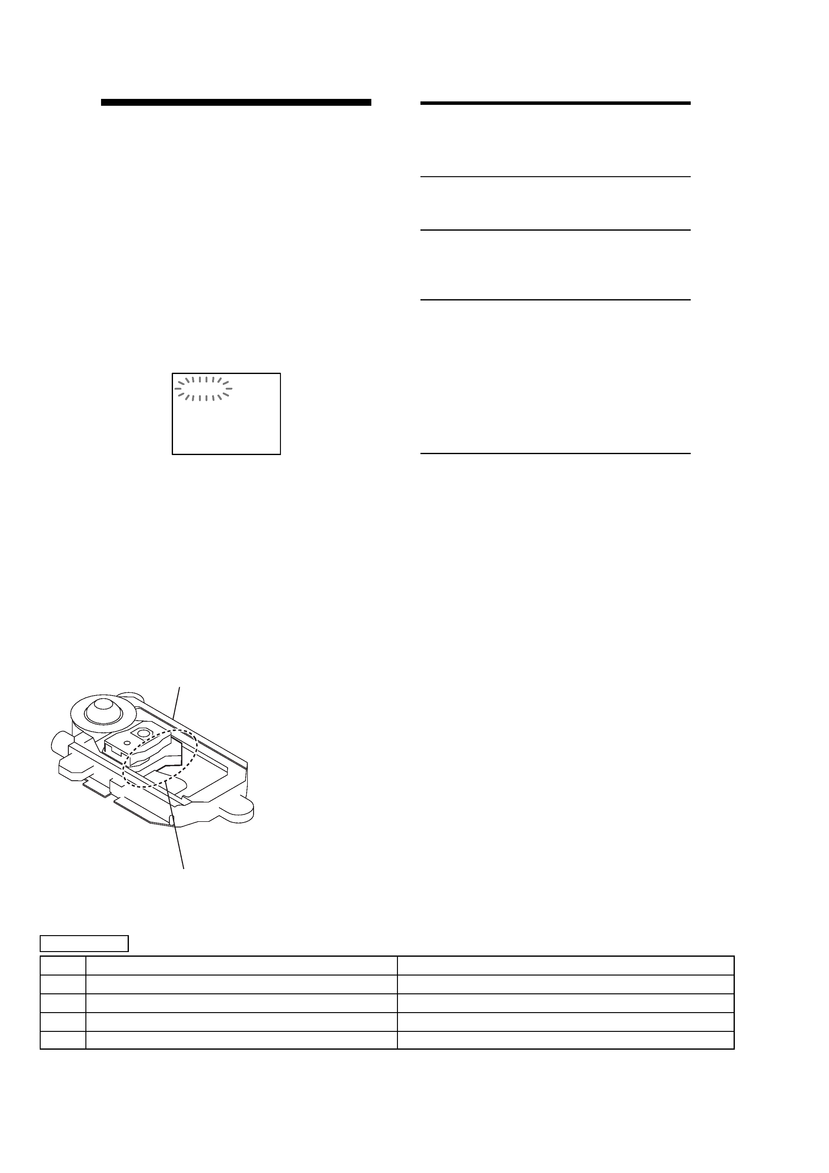
SELF-DIAGNOSIS
Self-diagnosis Function
(When letters/numbers appear in the
display)
The self-diagnosis function is activated to
prevent the system from malfunctioning. In
this case a five-character service number
(e.g., C 13 00) with a combination of a letter
and digits appears on the screen and the
front panel display. Refer to the following
table.
C:13:00
First three
characters of
the service
number
C 13
C 31
E XX
(xx is a number)
Cause and/or Corrective
Action
The disc is dirty.
, Clean the disc with a soft
cloth.
The disc is not inserted
correctly.
, Re-insert the disc
correctly.
To prevent a malfunction, the
system has performed the self-
diagnosis function.
, Contact your nearest Sony
dealer or local authorized
Sony service facility and
give the 5-character
service number.
Example: E 61 10
CHANGE OF OPTICAL PICK-UP
Optical Pick-up has been replaced from KHM-240AAA (TYPE A) to KHM-270AAA (TYPE B) from the middle of production.
In parallel with that, certain parts of DVD board have been changed.
TYPE A/B DISCRIMINATION
PARTS LIST OF EACH MODEL
DVD BOARD
REF
TYPE A
TYPE B
KHM-240AAA
KHM-270AAA
R076
1-216-837-11 METAL CHIP
22K
5%
1/10W
No Mount
R077
1-216-815-11 METAL CHIP
330
5%
1/10W
1-216-833-11 METAL CHIP
10K
5%
1/10W
R079
1-216-801-11 METAL CHIP
22
5%
1/10W
1-216-845-11 METAL CHIP
100K
5%
1/10W
SERVICING NOTE
SILVER: KHM-240AAA (TYPE A)
BLACK: KHM-270AAA (TYPE B)
optical device
Ver 1.3 2003. 05
3
HCD-C450
SAFETY CHECK-OUT
After correcting the original service problem, perform the following
safety checks before releasing the set to the customer:
Check the antenna terminals, metal trim, "metallized" knobs, screws,
and all other exposed metal parts for AC leakage. Check leakage as
described below.
LEAKAGE
The AC leakage from any exposed metal part to earth Ground and
from all exposed metal parts to any exposed metal part having a
return to chassis, must not exceed 0.5 mA (500 microampers).
Leakage current can be measured by any one of three methods.
1.
A commercial leakage tester, such as the Simpson 229 or RCA
WT-540A. Follow the manufacturers' instructions to use these
instruments.
2.
A battery-operated AC milliammeter. The Data Precision 245
digital multimeter is suitable for this job.
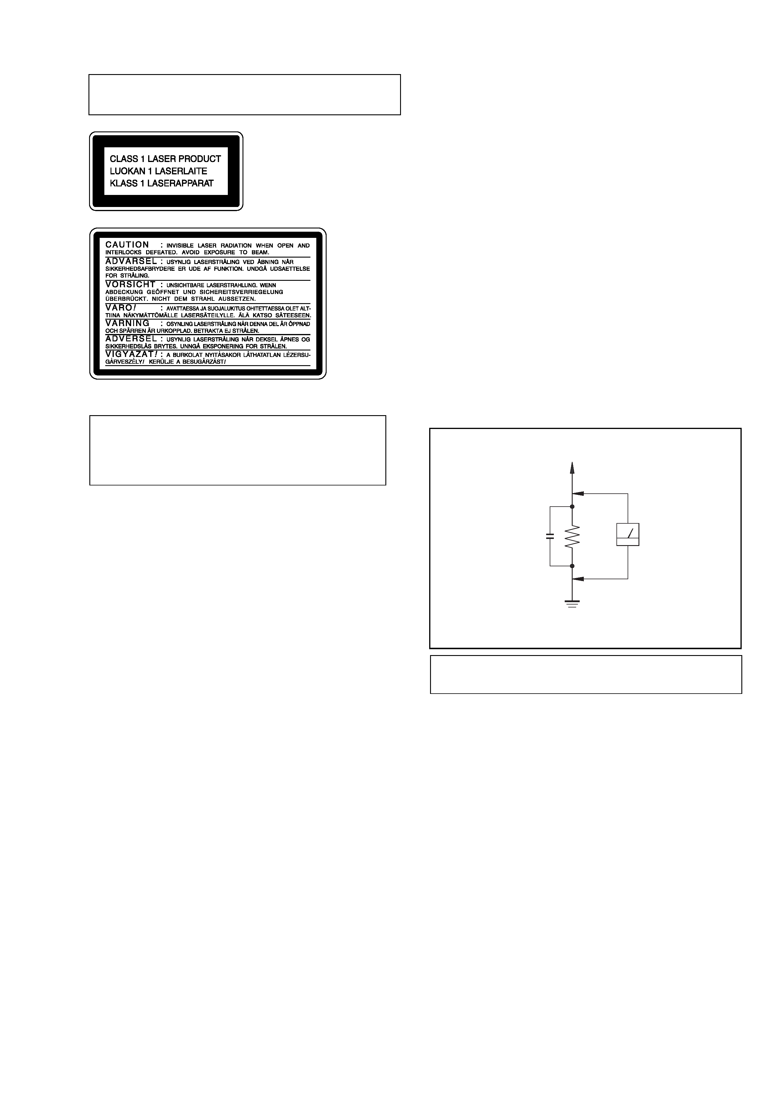
3.
Measuring the voltage drop across a resistor by means of a
VOM or battery-operated AC voltmeter. The "limit" indication
is 0.75 V, so analog meters must have an accurate low-voltage
scale. The Simpson 250 and Sanwa SH-63Trd are examples of
a passive VOM that is suitable. Nearly all battery operated
digital multimeters that have a 2V AC range are suitable. (See
Fig. A)
CAUTION
Use of controls or adjustments or performance of procedures
other than those specified herein may result in hazardous
radiation exposure.
Notes on chip component replacement
·Never reuse a disconnected chip component.
· Notice that the minus side of a tantalum capacitor may be
damaged by heat.
Flexible Circuit Board Repairing
·Keep the temperature of soldering iron around 270°C
during repairing.
· Do not touch the soldering iron on the same conductor of the
circuit board (within 3 times).
· Be careful not to apply force on the conductor when soldering
or unsoldering.
Laser component in this product is capable of emitting radiation
exceeding the limit for Class 1.
This appliance is classified as
a CLASS 1 LASER product.
The CLASS 1 LASER
PRODUCT MARKING is
located on the rear exterior.
This caution
label is located
inside the unit.
To Exposed Metal
Parts on Set
0.15
µF
1.5 k
AC
Voltmeter
(0.75 V)
Earth Ground
Fig. A. Using an AC voltmeter to check AC leakage.
NOTES ON HANDLING THE OPTICAL PICK-UP BLOCK
OR BASE UNIT
The laser diode in the optical pick-up block may suffer electrostatic
break-down because of the potential difference generated by the
charged electrostatic load, etc. on clothing and the human body.
During repair, pay attention to electrostatic break-down and also
use the procedure in the printed matter which is included in the
repair parts.
The flexible board is easily damaged and should be handled with
care.
NOTES ON LASER DIODE EMISSION CHECK
The laser beam on this model is concentrated so as to be focused on
the disc reflective surface by the objective lens in the optical pick-
up block. Therefore, when checking the laser diode emission,
observe from more than 30 cm away from the objective lens.
LASER DIODE AND FOCUS SEARCH OPERATION
CHECK
Carry out the "S curve check" in "CD section adjustment" and check
that the S curve waveform is output several times.
Ver 1.6
CHECKING
OF
OPERATIONS
WITH
REMOTE
COMMANDERS OF DIFFERENT MODELS
Some of the signal of remote commander vary between generation
of player.
Between DAV-S400/S500/S800/C450/C700/C900 and DAV-S550/
S880/C770/C900, remote commander signal codes of
"FUNCTION", "BAND", "ST/MONO" and "MEMORY" are
different.
Take notice of the above when you check the operation with remote
commanders of different models.
NOTE OF REPLACING THE DVD BOARD
When replacing the DVD board, since the adjustment value is not
set up correctly, "Drive Auto Adjustment" can't be performed.
In this case, initialize Memory in the following procedures.
Procedure:
1.Starting test mode. (See page 18)
2.Press the [2] key of the remote commander, and set the "DRIVE
MANUAL OPERATION". (See page 24)
3.Press the [6] key of the remote commander, and set the "6. Memory
Check". (See page 26)
4.Press the [CLEAR] key of the remote commander, and initialize
Memory.