SPECIFICATIONS
D99C CHASSIS
SERVICE MANUAL
CPD-E210
CPD-E210
US Model
Canadian Model
Chassis No. SCC-L31A-A
TRINITRON
® COLOR MONITOR
Picture tube
Video image area
Resolution
Standard image area
Input signal
Video
Sync
0.24 mm aperture grill pitch
17 inches measured diagonally
90-degree deflection
(16" maximum viewing image)
Approx. 327 X 243 mm (w/h)
(129/10 x 91/2 inches)
Horizontal: Max. 1600 dots
Vertical: Max. 1200 lines
Approx. 312 x 234 mm (w/h)
(121/4 x 91/4 inches)
Analog RGB (75 ohms typical)
0.7 Vp-p, ±5%, Positive
Separate HD/VD,
TTL Polarity Free
External Composite,
TTL Polarity Free (2K ohms impedance)
Deflection frequency
AC input voltage / current
Dimensions
Mass
Plug and Play
Horizontal: 30 to 85 KHz
Vertical: 48 to 120 Hz
100 to 120 V, 50/60 Hz, 1.7A
220 to 240V, 50/60Hz, 0.9A
404 x 413.5 x 419.5mm (w/h/d)
(159/10 x 163/10 x 161/2 inches)
Approx. 20.0 kg (44 lb 2 oz.)
DDC/DDC2B, DDC2Bi, GTF
Design and specifications are subject to change without notice.
869 Front.p65
10/20/1999, 10:25 AM
1
-- 2 --
CPD-E210
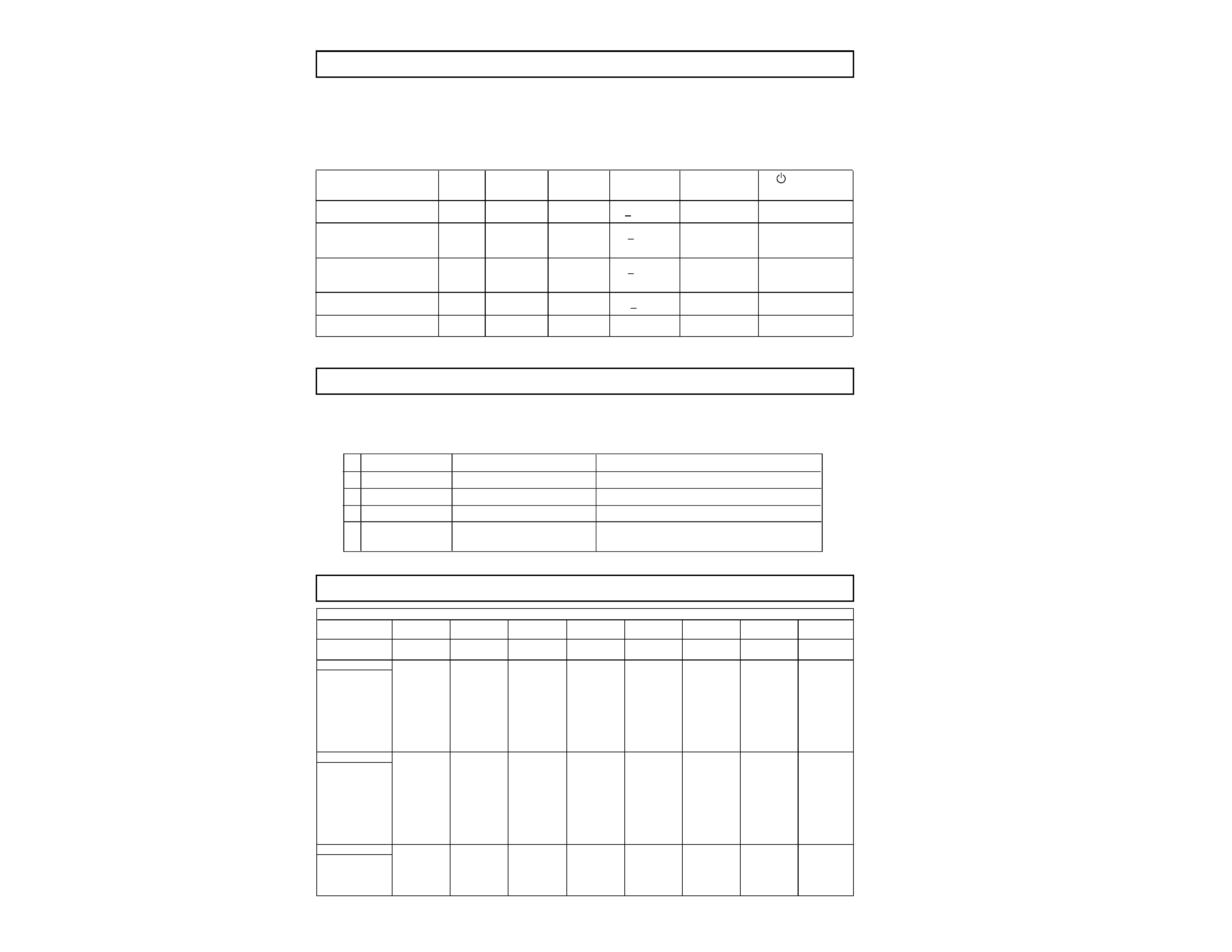
POWER MANAGEMENT
The power saving mode complies with the VESA Display Power Management Signaling standard. Each
state of power management shall be activated by the host computer terminating the appropriate sync
signals. Blanking the video must precede termination of the sync signals. The elapsed time counter
shall also be controlled by the host computer. Reactivation of the monitor shall be accomplished from
the host computer by re-establishing the normal sync signal.
Status
Area of Failure
LED Indication
1 Failure 1
HV or +B
Amber (0.5 second)/Off (0.5 second)
2 Failure 2
Amber (1.5 second)/Off (0.5 second)
3 Failure 3
ABL
Amber (0.5 second)/Off (1.5 second)
4 Aging/Self Test
Amber (0.5 second)/Off (0.5 second)/
Green (0.5 second)/Off (0.5 second)
H Stop or V Stop
TIMING SPECIFICATION
SELF DIAGNOSIS FUNCTION
When a failure occurs, the STANDBY/TIMER lamp will flash a set number of times to indicate the
possible cause of the problem. If there is more than one error, the lamp will identify the first of the
problem areas.
Power consumption
Screen
Horizontal
Vertical
Power
Recovery time
indicator
mode
(video)
sync signal
sync signal consumption
1
Normal operation
active
yes
yes
< 120 W
--
Green
2
Standby (1st mode)
blank
no
yes
< 15 W
Approx. 5 sec.
Green and Orange
Alternate
3
Suspend (2nd mode)
blank
yes
no
< 15 W
Approx. 5 sec.
Green and Orange
Alternate
4
Active-off (3rd mode)
blank
no
no
< 3 W
Approx. 10 sec.
Orange
5
Power-off
--
--
--
0 W
--
Off
Primary Mode
MODE
12345678
Resolution (H x V)
640 X 480
800 X 600
832 x624
1024 X 768
1024 X 768
720 X 400
640 X 480
1280 X 1024
Dot Clock (MHz)
25.175
56.250
57.283
78.750
94.500
28.322
36.000
135.000
HORIZONTAL
Hor. Freq. (kHz)
31.469
53.674
49.725
60.023
68.677
31.469
43.269
79.976
H-Total
31.778
18.631
20.111
16.660
14.561
31.777
23.111
12.504
H-Blanking
6.356
4.409
5.586
3.657
3.725
6.355
5.333
3.022
H-Front Porch
0.636
0.569
0.559
0.203
0.508
0.636
1.556
0.119
H-Sync.
3.813
1.138
1.117
1.219
1.016
3.813
1.556
1.067
H-Back Porch
1.907
2.702
3.910
2.235
2.201
1.907
2.222
1.837
H-Active
25.422
14.222
14.524
13.003
10.836
25.422
17.778
9.481
(µsec)
VERTICAL
Ver. Freq. (Hz)
59.940
85.061
74.550
75.029
84.997
70.087
85.008
75.025
V-Total
525
631
667
800
808
449
509
1066
V-Blanking
45
31
43
32
40
49
29
42
V-Front Porch
10
1111
12
1
1
V-Sync.
2333323
3
V-Back Porch
33
27
39
28
36
35
25
38
V-Active
480
600
624
768
768
400
480
1024
(lines)
SYNC.
Int (G)
NO
NO
NO
NO
NO
NO
NO
NO
Ext (H/V)/Polarity
YES -/-
NO +/+
YES -/-
YES +/+
YES +/+
YES -/+
YES -/-
YES +/+
Ext (CS)/Polarity
NO
NO
NO
NO
NO
NO
NO
NO
Int/Non Int
NON INT
NON INT
NON INT
NON INT
NON INT
NON INT
NON INT
NON INT
TIMING SPECIFICATION
-- 3 --
CPD-E210
TABLE OF CONTENTS
Section
Title
Page
Safety Check-Out Instructions ............................................................... 4
1. GENERAL .................................................................................. 5
2. DISASSEMBLY
2-1. Cabinet Removal .......................................................... 12
2-2. Service Position ............................................................ 12
2-3. A, D & H Board Removal .............................................. 12
2-4. Picture Tube Removal .................................................. 13
3. SAFETY RELATED ADJUSTMENTS ............................ 14
4. ADJUSTMENTS ..................................................................... 15
5. DIAGRAMS
5-1. Block Diagram .............................................................. 19
5-2. Circuit Boards Location ................................................ 22
5-3. Schematic Diagrams and Printed Wiring Boards ......... 22
1. D Board - Schematic Diagram ................................ 23
2. H Board - Schematic Diagram ................................ 28
3. A Board - Schematic Diagram ................................ 30
5-4. Semiconductors ........................................................... 33
6. EXPLODED VIEWS
6-1. Chassis ......................................................................... 34
6-2. Packing Materials ......................................................... 35
7. ELECTRICAL PARTS LIST ............................................... 36
-- 4 --
CPD-E210
SAFETY CHECK-OUT
After correcting the original service problem, perform the
following safety checks before releasing the set to the
customer:
Leakage Test
The AC leakage from any exposed metal part to earth ground
and from all exposed metal parts to any exposed metal part
having a return to chassis, must not exceed 0.5 mA (500
microampere). Leakage current can be measured by any one
of three methods.
WARNING!!
NEVER TURN ON THE POWER IN A CONDITION IN WHICH THE
DEGAUSS COIL HAS BEEN REMOVED.
SAFETY-RELATED COMPONENT WARNING!!
COMPONENTS IDENTIFIED BY SHADING AND MARK
ON THE
SCHEMATIC DIAGRAMS, EXPLODED VIEWS AND IN THE PARTS
LIST ARE CRITICAL FOR SAFE OPERATION. REPLACE THESE
COMPONENTS WITH SONY PARTS WHOSE PART NUMBERS
APPEAR AS SHOWN IN THIS MANUAL OR IN SUPPLEMENTS
PUBLISHED BY SONY. CIRCUIT ADJUSTMENTS THAT ARE
CRITICAL FOR SAFE OPERATION ARE IDENTIFIED IN THIS
MANUAL. FOLLOWTHESE PROCEDURES WHENEVER CRITICAL
COMPONENTS ARE REPLACED OR IMPROPER OPERATION IS
SUSPECTED.
AVERTISSEMENT!!
NE JAMAIS METTRE SOUS TENSION QUAND LA BOBINE DE
DEMAGNETISATION EST ENLEVEE.
ATTENTION AUX COMPOSANTS RELATIFS A LA SECURITE!!
LES COMPOSANTS IDENTIFIES PAR UNE TRAME ET PAR UNE
MARQUE
SUR LES SCHEMAS DE PRINCIPE, LES VUES
EXPLOSEES ET LES LISTES DE PIECES SONT D'UNE
IMPORTANCE
CRITIQUE
POUR
LA
SECURITE
DU
FONCTIONNEMENT.
NE LES REMPLACER QUE PAR DES
COMPOSANTS SONY DONT LE NUMERO DE PIECE EST
INDIQUE DANS LE PRESENT MANUEL OU DANS DES
SUPPLEMENTS PUBLIES PAR SONY. LES REGLAGES DE
CIRCUIT DONT L'IMPORTANCE EST CRITIQUE POUR LA
SECURITE DU FONCTIONNEMENT SONT IDENTIFIES DANS LE
PRESENT MANUEL. SUIVRE CES PROCEDURES LORS DE
CHAQUE REMPLACEMENT DE COMPOSANTS CRITIQUES, OU
LORSQU'UN MAUVAIS FONTIONNEMENT SUSPECTE.
1. Check the area of your repair for unsoldered or poorly-
soldered connections. Check the entire board surface
for solder splashes and bridges.
2. Check the interboard wiring to ensure that no wires are
"pinched" or contact high-wattage resistors.
3. Check that all control knobs, shields, covers, ground
straps, and mounting hardware have been replaced.
Be absolutely certain that you have replaced all the
insulators.
4. Look for unauthorized replacement parts, particularly
transistors, that were installed during a previous repair.
Point them out to the customer and recommend their
replacement.
5. Look for parts which, though functioning, show obvious
signs of deterioration. Point them out to the customer
and recommend their replacement.
6. Check the line cords for cracks and abrasion.
Recommend the replacement of any such line cord to
the customer.
7. Check the B+ and HV to see if they are specified values.
Make sure your instruments are accurate; be suspicious
of your HV meter if sets always have low HV.
8. Check the antenna terminals, metal trim, "metallized"
knobs, screws, and all other exposed metal parts for
AC Leakage. Check leakage as described below.
1. A commercial leakage tester, such as the Simpson 229 or
RCA WT-540A. Follow the manufacturers' instructions to use
these instructions.
2. A battery-operated AC milliammeter. The Data Precision
245 digital multimeter is suitable for this job.
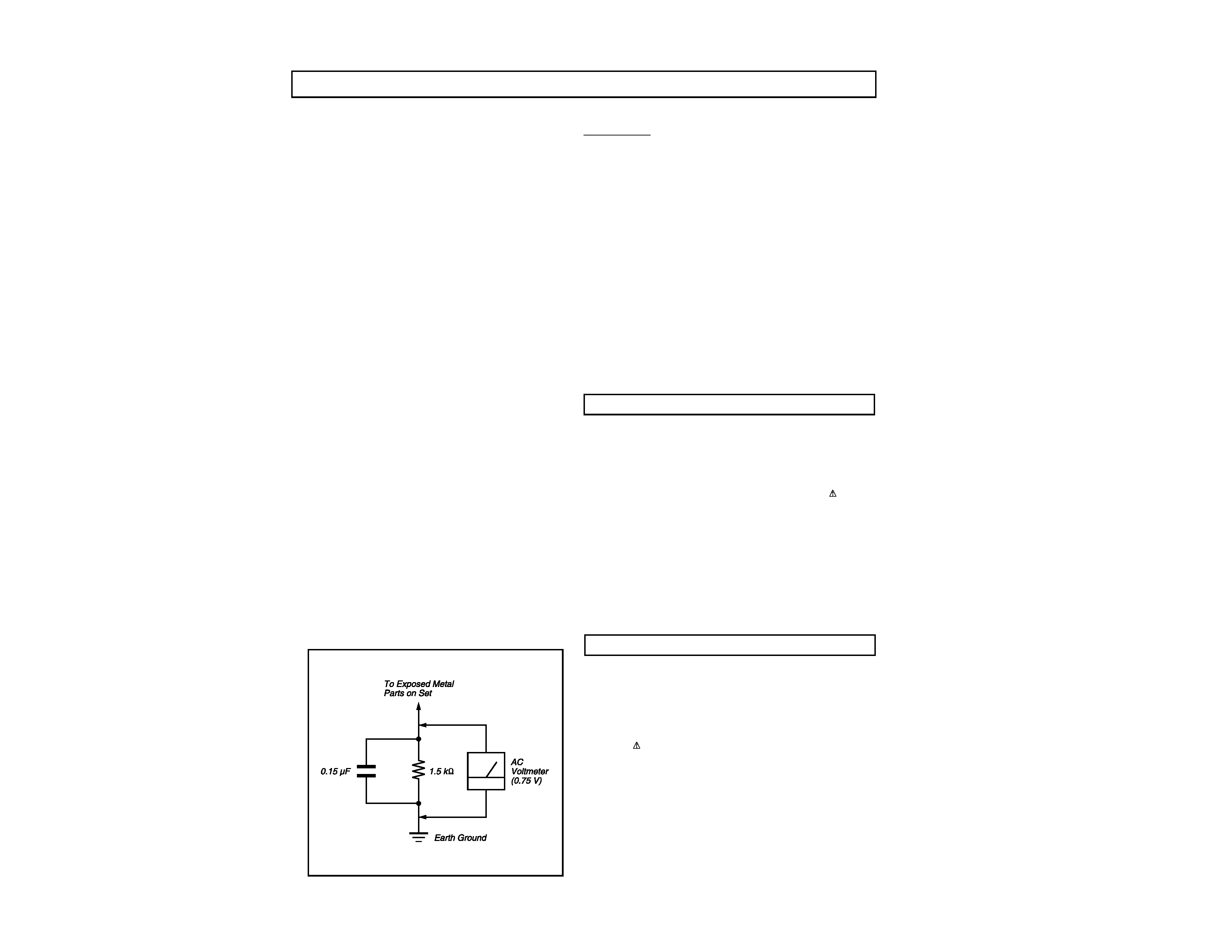
3. Measuring the voltage drop across a resistor by means of
a VOM or battery-operated AC voltmeter. The "limit"
indication is 0.75 V, so analog meters must have an accurate
low voltage scale. The Simpson's 250 and Sanwa SH-63Trd
are examples of passive VOMs that are suitable. Nearly
all battery operated digital multimeters that have a 2V AC
range are suitable. (See Figure A)
Figure A
--
5
--
CPD-E210
5
US
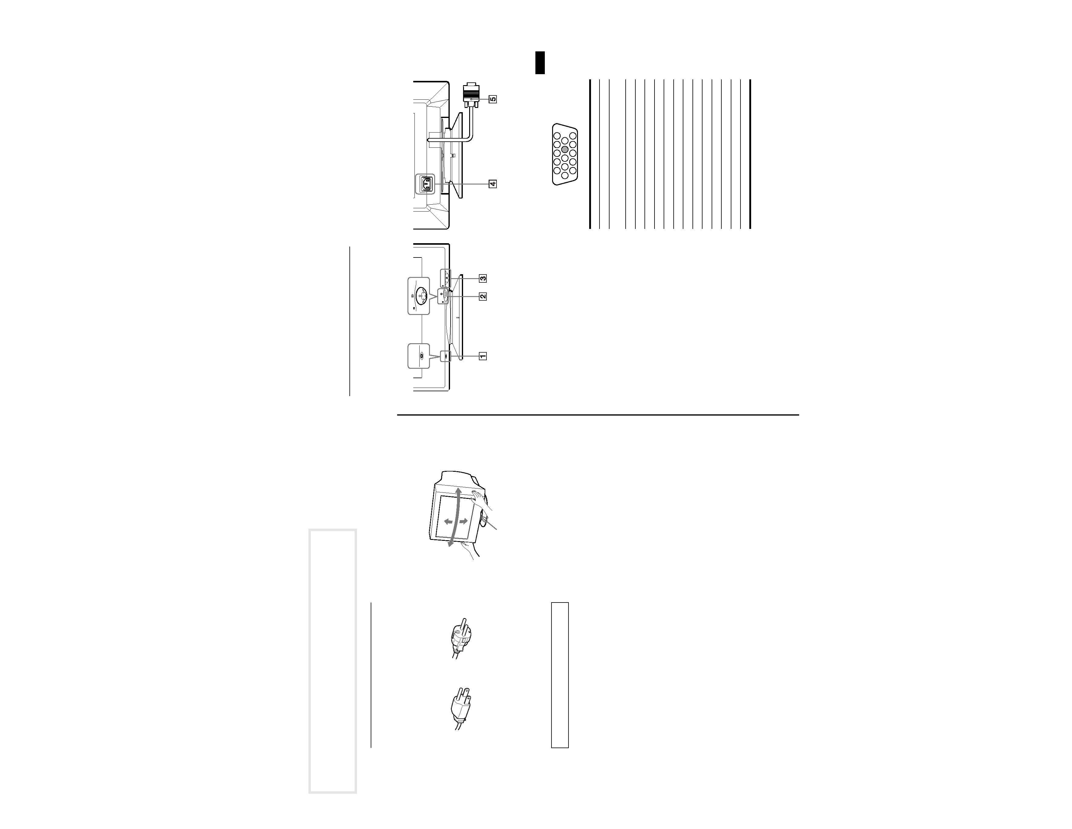
Identifying parts and controls
See the pages in parentheses for further details.
1 RESET button (page 12)
This button resets the adjustments to the factory settings.
2 Control button (page 9)
The control button is used to display the menu and make
adjustments to the monitor, including brightness and contrast
adjustments.
3 1 (power) switch and indicator (pages 7, 13, 16)
This button turns the monitor on and off. The power indicator
lights up in green when the monitor is turned on, and either
flashes in green and orange, or lights up in orange when the
monitor is in power saving mode.
4 AC IN connector (page 6)
This connector provides AC power to the monitor.
5 Video input connector (HD15) (page 6)
This connector inputs RGB video signals (0.700 Vp-p,
positive) and sync signals.
* DDC (Display Data Channel) is a standard of VESA.
AC IN
MENU
RESET
MENU
RESET
Rear
Front
Pin No.
Signal
1Red
2
Green
(Sync on Green)
3Blue
4
ID (Ground)
5
DDC Ground*
6
Red Ground
7
Green Ground
8
Blue Ground
9
10
Ground
11
ID (Ground)
12
Bi-Directional Data (SDA)*
13
H. Sync
14
V. Sync
15
Data Clock (SCL)*
1 2
3 4 5
8
7
6
11 12 13 14 15
10
9
SECTION 1
GENERAL
The following are partial abstracts from the Operating Instruction
Manual. The page numbers shown reflect those of the Operating
Instruction Manual.
4
Precautions
Warning on power connections
· Use the supplied power cord. If you use a different power cord,
be sure that it is compatible with your local power supply.
For the customers in the U.S.A.
If you do not use the appropriate cord, this monitor will not
conform to mandatory FCC standards.
· Before disconnecting the power cord, wait at least 30 seconds
after turning off the power to allow the static electricity on the
screen's surface to discharge.
· After the power is turned on, the screen is demagnetized
(degaussed) for about 5 seconds. This generates a strong
magnetic field around the screen which may affect data stored
on magnetic tapes and disks placed near the monitor. Be sure to
keep magnetic recording equipment, tapes, and disks away
from the monitor.
Installation
Do not install the monitor in the following places:
· on surfaces (rugs, blankets, etc.) or near materials (curtains,
draperies, etc.) that may block the ventilation holes
· near heat sources such as radiators or air ducts, or in a place
subject to direct sunlight
· in a place subject to severe temperature changes
· in a place subject to mechanical vibration or shock
· on an unstable surface
· near equipment which generates magnetism, such as a
transformer or high voltage power lines
· near or on an electrically charged metal surface
Maintenance
· Clean the screen with a soft cloth. If you use a glass cleaning
liquid, do not use any type of cleaner containing an anti-static
solution or similar additive as this may scratch the screen's
coating.
· Do not rub, touch, or tap the surface of the screen with sharp or
abrasive items such as a ballpoint pen or screwdriver. This type
of contact may result in a scratched picture tube.
· Clean the cabinet, panel and controls with a soft cloth lightly
moistened with a mild detergent solution. Do not use any type
of abrasive pad, scouring powder or solvent, such as alcohol or
benzene.
Transportation
When you transport this monitor for repair or shipment, use the
original carton and packing materials.
Use of the tilt-swivel
This monitor can be adjusted within the angles shown below. To
find the center of the monitor's turning radius, align the center of
the monitor's screen with the centering dots on the stand.
Hold the monitor at the bottom with both hands when you turn it
horizontally or vertically. Be careful not to pinch your fingers at
the back of the monitor when you tilt the monitor up vertically.
The equipment should be installed near an easily accessible
outlet.
Example of plug types
for 100 to 120 V AC
for 200 to 240 V AC
90°
5°
90°
15°
Centering dots