1
Model Name Using Similar Mechanism
NEW
CD Mechanism Type
CDM-2811DAA
Optical Pick-up Name
DAX-11D
SERVICE MANUAL
US Model
D-191/192CK/193
Canadian Model
D-191
AEP Model
UK Model
D-190/191/191SR/192CK/193
E Model
Australian Model
D-191/192CK/193
Chinese Model
D-191/193
D-190/191/191SR/192CK/193
COMPACT DISC COMPACT PLAYER
MICROFILM
Photo: D-191
CD player
System
Compact disc digital audio system
Laser diode properties
Material: GaAlAs
Wave length:
= 780 nm
Emission duration: Continuous
Laser output: Less than 44.6 µW (This output
is the value measured at a distance of 200
mm from the objective lens surface on the
optical pick-up block with 7 mm aperture.)
Error correction
Sony Super Strategy Cross Interleave Reed
Solomon Code
D-A conversion
1-bit quartz time-axis control
Frequency response
20 - 20,000 Hz +1/3 dB
(measured by EIAJ CP-307)
Output (at 4.5 V input level)
Headphones (stereo minijack)
Approx. 5 mW + approx. 5 mW
at 16 ohms
(Approx. 2 mW + approx. 2 mW
at 16 ohms*)
*For the customers in France
SPECIFICATIONS
Continued on next page
General
Power requirements
For the area code of the model you purchased,
check the upper left side of the bar code on the
package.
· Sony NC-DMAA rechargeable battery:
2.4 V DC, Ni-Cd, 700 mAh (D-193)
· Two LR6 (size AA) batteries: 3 V DC
· AC power adaptor (DC IN 4.5 V jack):
US/CND/E92/MX model: 120 V, 60 Hz
AEP/FR/EE/E13/G model:
220 - 230 V, 50/60 Hz
UK model: 230 - 240 V, 50 Hz
EA model: 110 - 240 V, 50/60 Hz
AUS model: 240 V, 50 Hz
JEW/E33 model: 100 - 240 V, 50/60 Hz
HK model: 220 V, 50/60 Hz
CH/AR model: 220 V, 50 Hz
· Sony DPM-300P mount plate for use on car
battery: 4.5 V DC
Dimensions (w/h/d) (without projecting parts
and controls)
Approx. 131
× 28 × 148 mm
(5 1/4
× 1 1/9 × 5 4/5 in.)
Mass (without rechargeable batteries)
Approx. 220 g (7.8 oz.)
Operating temperature
5°C - 35°C (41°F - 95°C)
Ver 1.2 1999. 05
with SUPPLEMENT-1
(9-926-937-81)
with SUPPLEMENT-2
(9-926-937-82)

2
CAUTION
Use of controls or adjustments or performance of proce-
dures other than those specified herein may result in haz-
ardous radiation exposure.
Flexible Circuit Board Repairing
· Keep the temperature of the soldering iron around 270°C during
repairing.
· Do not touch the soldering iron on the same conductor of the
circuit board (within 3 times).
· Be careful not to apply force on the conductor when soldering
or unsoldering.
Notes on Chip Component Replacement
· Never reuse a disconnected chip component.
· Notice that the minus side of a tantalum capacitor may be
damaged by heat.
"La Fiesta" model
The "La Fiesta" model is same as the E13, E33 or E92 models
except for upper lid assy and individual carton.
See page 26 for part No. of upper lid assy, page 31 for part No. of
individual carton.
· E13 : AC 220 - 230V area in E model
· E33 : AC 100 - 240V area in E model
· E92 : AC 120V area in E model
Supplied accessories
For the area code of the model you purchased,
check the upper left side of the bar code on the
package.
D-190
Earphones (1)
Connecting cord (Phono plug
× 2 stereo
miniplug) (1)
D-191
AC power adaptor (1)
Headphones (1)*1
Earphones (1)*2
Connecting cord (Phono plug
× 2 stereo
miniplug) (1)*3
AC plug adaptor (1)*4
*1 Supplied with US and CND models
*2 Not supplied with US and CND models
*3 Not supplied with US model
*4 Supplied with E33, E13, and EA models
D-191SR
AC power adaptor (1)
Earphones (1)
Active speakers (SRS-A5) (1)
D-192CK
AC power adaptor (1)
Headphones (1)*1
Earphones (1)*2
Connecting cord (Phono plug
× 2 stereo
miniplug) (1)*2
Car connecting pack (1)
Car battery cord (1)
Mount plate (1)
Velcro tape (2)
Spare fuse (1)
Spiral tube (1)
AC plug adaptor (1)*3
*1 Supplied with US model
*2 Not supplied with US model
*3 Supplied with E33, E13, and EA models
D-193
AC power adaptor (1)
Headphones (1)*1
Earphones (1)*2
Rechargeable batteries (2)
Connecting cord (Phono plug
× 2 stereo
miniplug) (1)*2
AC plug adaptor (1)*3
*1 Supplied with US model
*2 Not supplied with US model
*3 Supplied with E33, E13, and EA models
Design and specifications are subject to change without
notice.
SAFETY-RELATED COMPONENT WARNING!!
COMPONENTS IDENTIFIED BY MARK
! OR DOTTED LINE
WITH MARK
! ON THE SCHEMATIC DIAGRAMS AND IN
THE PARTS LIST ARE CRITICAL TO SAFE OPERATION.
REPLACE THESE COMPONENTS WITH SONY PARTS WHOSE
PART NUMBERS APPEAR AS SHOWN IN THIS MANUAL OR
IN SUPPLEMENTS PUBLISHED BY SONY.
ATTENTION AU COMPOSANT AYANT RAPPORT
À LA SÉCURITÉ!!
LES COMPOSANTS IDENTIFIÉS PAR UNE MARQUE
! SUR LES
DIAGRAMMES SCHÉMATIQUES ET LA LISTE DES PIÈCES SONT
CRITIQUES POUR LA SÉCURITÉ DE FONCTIONNEMENT. NE
REMPLACER CES COMPOSANTS QUE PAR DES PIÈCES SONY
DONT LES NUMÉROS SONT DONNÉS DANS CE MANUEL OU
DANS LES SUPPLÉMENTS PUBLIÉS PAR SONY.
This Compact Disc player is
classified as a CLASS 1
LASER product.
The CLASS 1 LASER
PRODUCT table is located
on the bottom exterior.
· Abbreviation
AR
: Arabic model
AUS : Australian model
BR
: Brazilian model
CH
: Chinese model
CND : Canadian model
E13 : AC 220-230V area in E model
E33 : AC 100-240V area in E model
E92 : AC 120V area in E model
EA
: Saudi Arabia model
EE
: East European model
FR
: French model
G
: German model
MX : Mexican model
3
TABLE OF CONTENTS
1. SERVICE NOTE ................................................................. 3
2. GENERAL ............................................................................ 4
3. DISASSEMBLY
3-1. Cabinet (Rear) Sub Assy ..................................................... 5
3-2. Main Board ......................................................................... 5
3-3. MD Assy ............................................................................. 5
4. ELECTRICAL ADJUSTMENTS ................................... 6
5. DIAGRAMS
5-1. IC Pin Descriptions ............................................................. 7
5-2. Block Diagram .................................................................... 9
5-3. Printed Wiring Board ........................................................ 12
5-4. Schematic Diagram Main Section (1/2) ........................ 15
5-5. Schematic Diagram Main Section (2/2) ........................ 17
6. EXPLODED VIEWS
6-1. Cabinet Section ................................................................. 20
6-2. MD Section ....................................................................... 22
7. ELECTRICAL PARTS LIST ......................................... 23
SECTION 1
SERVICE NOTE
NOTES ON HANDLINGTHE OPTICAL PICK-UP BLOCK OR
BASE UNIT
The laser diode in the optical pick-up block may suffer electrostatic
breakdown because of the potential difference generated by the
charged electrostatic load, etc. on clothing and the human body.
During repair, pay attention to electrostatic breakdown and also use
the procedure in the printed matter which is included in the repair
parts.
The flexible board is easily damaged and should be handled with
care.
NOTES ON LASER DIODE EMISSION CHECK
The laser beam on this model is concentrated so as to be focused on
the disc reflective surface by the objective lens in the optical pick-up
block. Therefore, when checking the laser diode emission, observe
from more than 30 cm away from the objective lens.
Before Replacing the Optical Pick-Up Block
Please be sure to check throughly the parameters as par the "Optical
Pick-Up Block Checking Procedures" (Part No.: 9-960-027-11)
issued separately before replacing the optical pick-up block.
Note and specifications required to check are given below.
· FOK output : IC501 @ pin
When checking FOK, remove the lead wire to disc motor.
· S curve P-to-P value : 2.0Vp-p IC501 $· pin
When checking S curve P-to-P value, remove the lead wire to
disc motor.
· RF signal P-to-P value : 0.6 - 1.3Vp-p
· Traverse signal P-to-P value : 0.8 - 2.8Vp-p
· The repairing grating holder is impossible.
Precautions for Checking Emission of Laser Diode
Laser light of the equipment is focused by the objective lens in the
optical pick-up so that the light focuses on the reflection surface of
the disc.
Therefore, be sure to keep your eyes more than 30 cm apart from
the objective lens when you check the emission of laser diode.
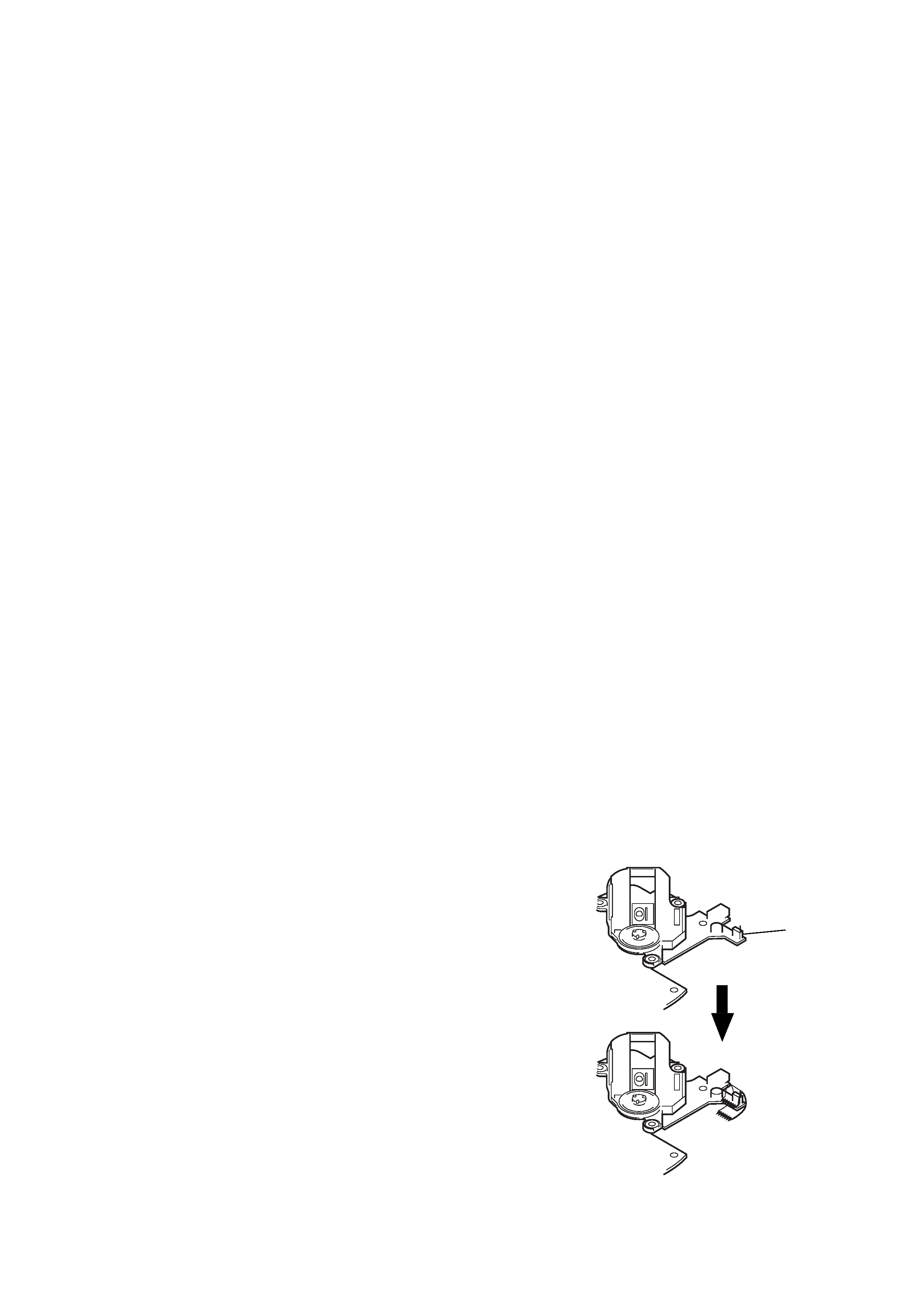
Laser Diode Checking Methods
During normal operation of the equipment, emission of the laser
diode is prohibited unless the upper lid is closed while turning ON
the S808 (push switch type).
The following checking method for the laser diode are operable.
Emission of the laser diode is visually checked
1. Open the upper lid.
2. Push the S808 as shown in Fig. 1.
3. Check the objective lens for confirming normal emission of
the laser diode. If not emitting, there is a trouble in the
automatic power control circuit or the optical pick-up.
During normal operation, the laser diode is turned ON about
2.5 seconds for focus searching.
Fig. 1 Method to push the S808
S808
4
SECTION 2
GENERAL
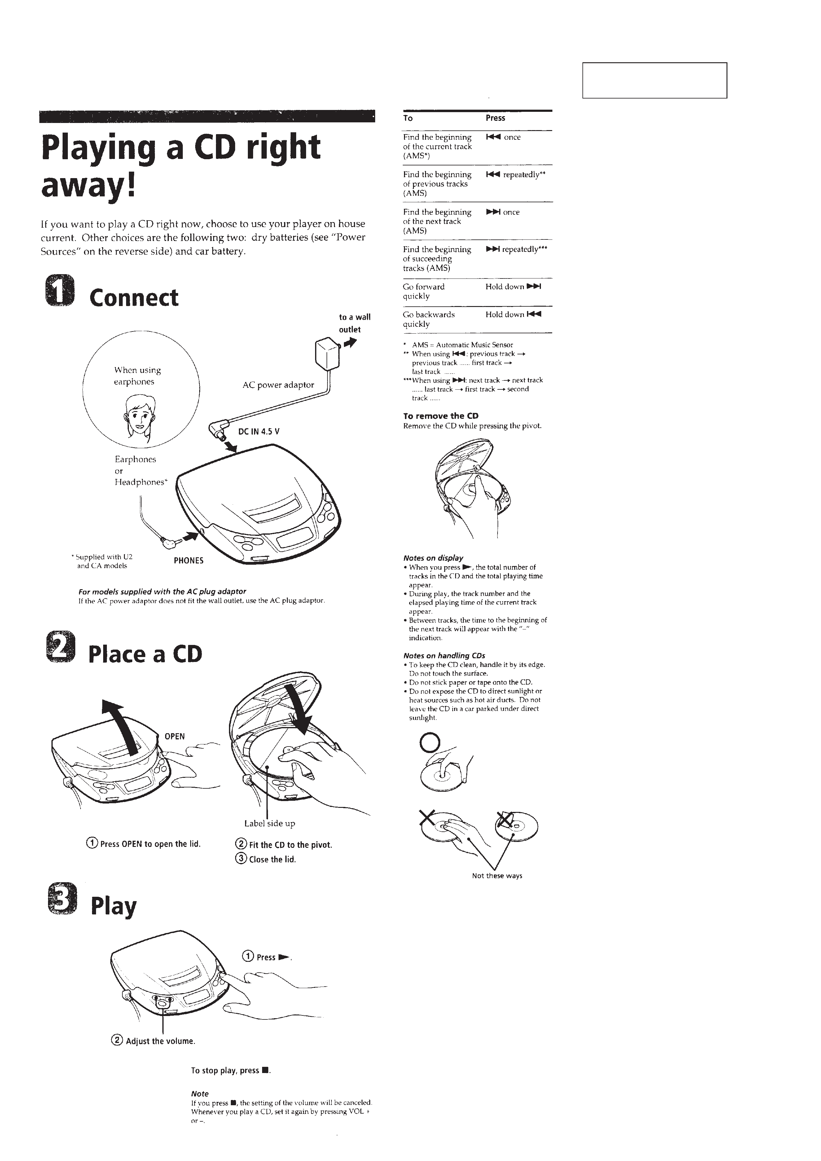
This section is extracted
from instruction manual.
4
5
SECTION 3
DISASSEMBLY
Note : Follow the disassembly procedure in the numerical order given.
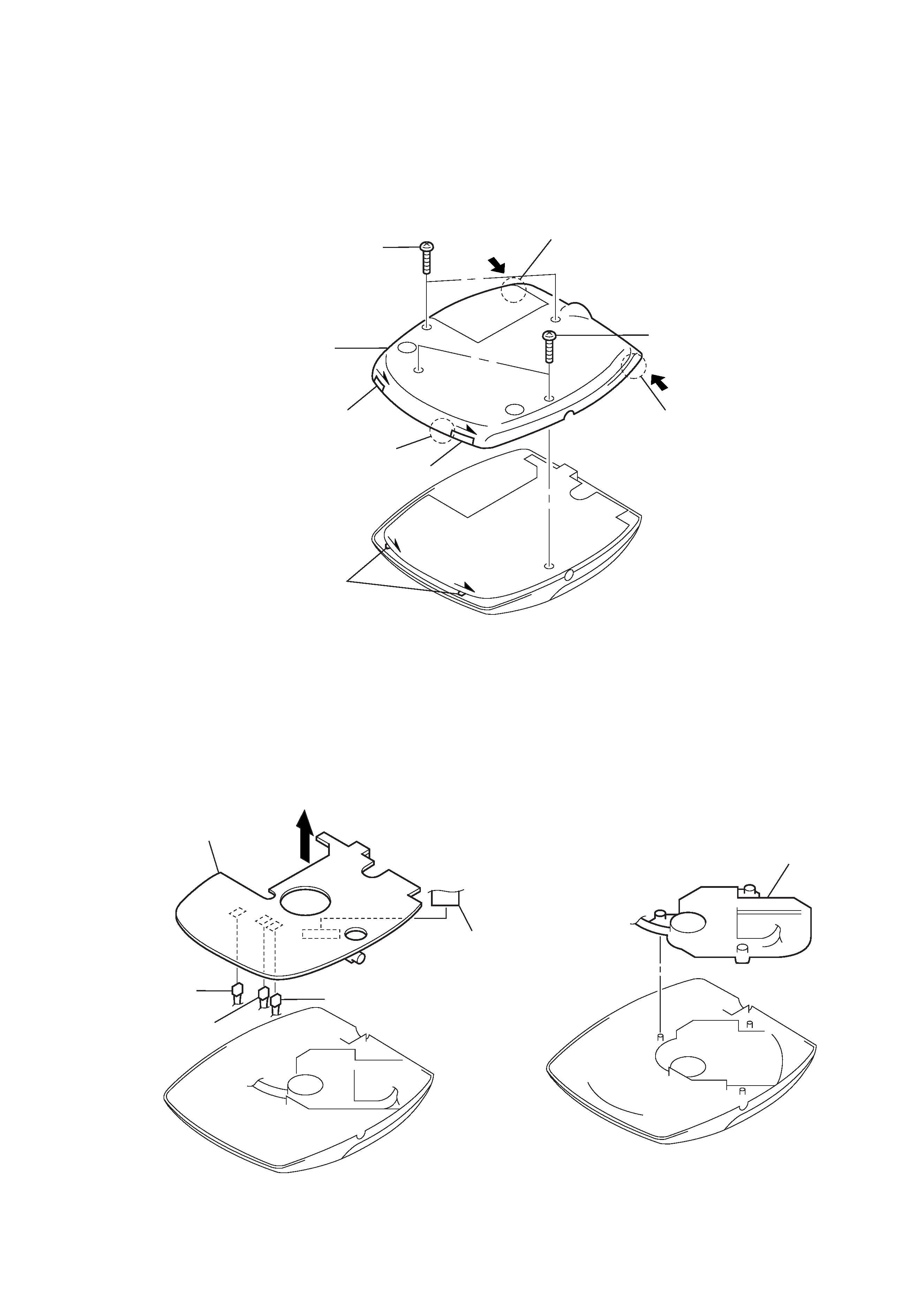
3-1. CABINET (REAR) SUB ASSY
Note : When installing, fit the knobs (H-B) and switches.
3-2. MAIN BOARD
3-3. MD ASSY
1 screws (B2x10) (G), tapping
2 screws (B2x10) (G), tapping
3 claw
4 claw
5 claw
6 cabinet (rear) sub assy
knob (H-B)
knob (H-B)
switches
1 CN501
5 MAIN board
2 CN502
3 CN503
4 CN504
1 MD assy