CX-LEM200
US Model
Canadian Model
AEP Model
UK Model
E Model
Australian Model
SERVICE MANUAL
MICRO HI-FI COMPONENT SYSTEM
Sony Corporation
Personal Audio Group
Published by Sony Engineering Corporation
9-877-164-04
2005C16-1
© 2005.03
CX-LEM200 is the Amplifier, CD player, Tape
Deck and Tuner section in XR-EM200.
SPECIFICATIONS
Ver. 1.3 2005.03
Model Name Using Similar Mechanism
NEW
CD
CD Mechanism Type
KSM-213EDP
Section
Base Unit Name
BU-K7BD44B
Optical Pick-up Name
KSS-213E/C2N
TAPE
Model Name Using Similar Mechanism
NEW
Section
Tape Transport Mechanism Type
CMAL5Z220A
TUNER
FM tuning range
87.5 MHz to 108 MHz
FM usable sensitivity (IHF)
16.8 dBf
FM antenna terminal
75 ohms (unbalanced)
MW tuning range
531 kHz to 1602 kHz
AM tuning range
530 kHz to 1710 kHz (10 kHz step)
531 kHz to 1710 kHz (9 kHz step)
US and CND models:
AEP, UK, E and AUS models:
AM usable sensitivity
350
µV/m
AM antenna
Loop antenna
AMPLIFIER
Power output
(AEP and UK models)
Rated: 8 W + 8 W(6
, T.H.D. 1 %,
1 kHz/DIN 45500)
Reference: 10 W + 10 W(6
, T.H.D.
10 %, 1 kHz/DIN 45324)
MUSIC POWER
20 W + 20 W
Input
AUX IN: 800 mV
Outputs
SPEAKERS: 6
or more
PHONES: 32
or more
CASSETTE DECK
Track format
4 tracks, 2 channels stereo
Frequency response
50 Hz 10000 Hz
Recording system
AC bias
Heads
Recording/playback
× 1, erase × 1
CD PLAYER
Laser
Semiconductor laser (
= 780 nm)
Emission duration: continuous
D/A converter
1 bit dual
Signal-to-noise ratio
95 dB (1 kHz, 0 dB)
Wow and flutter
Unmeasurable
GENERAL
230 V AC, 50/60 Hz (AEP, UK)
Power requirements
120 V AC, 60 Hz (US, CND, MX, TW)
Power consumption
40 W
Power consumption in standby mode
with ECO mode on: 0.3 W
with ECO mode off: 6 W
Dimensions (w/h/d)
Approx. 163
× 230.5 × 243 mm
Mass
Approx. 3.0 kg
Supplied accessories:
FM antenna (1)
AM antenna (1)
Remote commander (1)
Batteries (2)
Specifications and external appearance are subject to change
without notice.
AUDIO POWER SPECIFICATIONS:
(U.S.A. model only)
POWER OUTPUT AND TOTAL HARMONIC DISTORTION:
With 6-ohm loads, both channels driven, from 100 - 10,000 Hz;
rated 10 W per channel minimum RMS power, with no more than
10% total harmonic distortion from 250 mW to rated output.
220-240V AC, 50/60Hz (E15)
220V AC, 60Hz (KR)
220-240V AC,50/60Hz (SP, MY)
220-240V AC, 50/60Hz (AUS)
Voltage Selector models:
110-120V or 220-240V AC 50/60Hz
Adjustable with voltage selector
· Abbreviation
AUS : Australian model.
CND : Canadian model.
SP
: Singapore model.
MY : Malaysia model.
TW : Taiwan model.
KR
: Korean model.
E51 : Chilean and Peruvian models.
MX : Mexican model.
2
CX-LEM200
1. SERVICING NOTES ······················································· 3
2. GENERAL ·········································································· 5
3. DISASSEMBLY
3-1. Rear Cabinet ··································································· 7
3-2. CD Cabinet Section, Front Panel Section ······················· 8
3-3. CD Mechanism Deck ······················································ 8
3-4. CONTROL Board ··························································· 9
3-5. Tape Mechanism Deck ···················································· 9
3-6. Cassette Door Assy ······················································· 10
3-7. POWER Board, MAIN Board ······································ 10
3-8. Optical Pick-up (KSS-213E/C2N) ································ 11
4. MECHANICAL ADJUSTMENTS ····························· 12
5. ELECTRICAL ADJUSTMENTS ······························· 12
6. DIAGRAMS ······································································ 15
6-1. Block Diagram CD Section ··································· 17
6-2. Block Diagram Main Section ································ 18
6-3. Printed Wiring Board CD Section ························· 19
6-4. Schematic Diagram CD Section ···························· 20
6-5. Printed Wiring Boards Main Section ····················· 21
6-6. Schematic Diagram Main Section ························· 22
6-7. Printed Wiring Board Control Section ··················· 23
6-8. Schematic Diagram Control Section ······················ 24
6-9. Printed Wiring Board Power Section ····················· 25
6-10. Schematic Diagram Power Section ······················ 26
6-11. IC Pin Function Description ······································· 28
7. EXPLODED VIEWS
7-1. Cabinet Section ····························································· 30
7-2. Front Panel Section ······················································· 31
7-3. CD Cabinet Section ······················································ 32
7-4. KSM-213EDP ······························································· 33
8. ELECTRICAL PARTS LIST ······································· 34
TABLE OF CONTENTS
Ver 1.1 2003.06
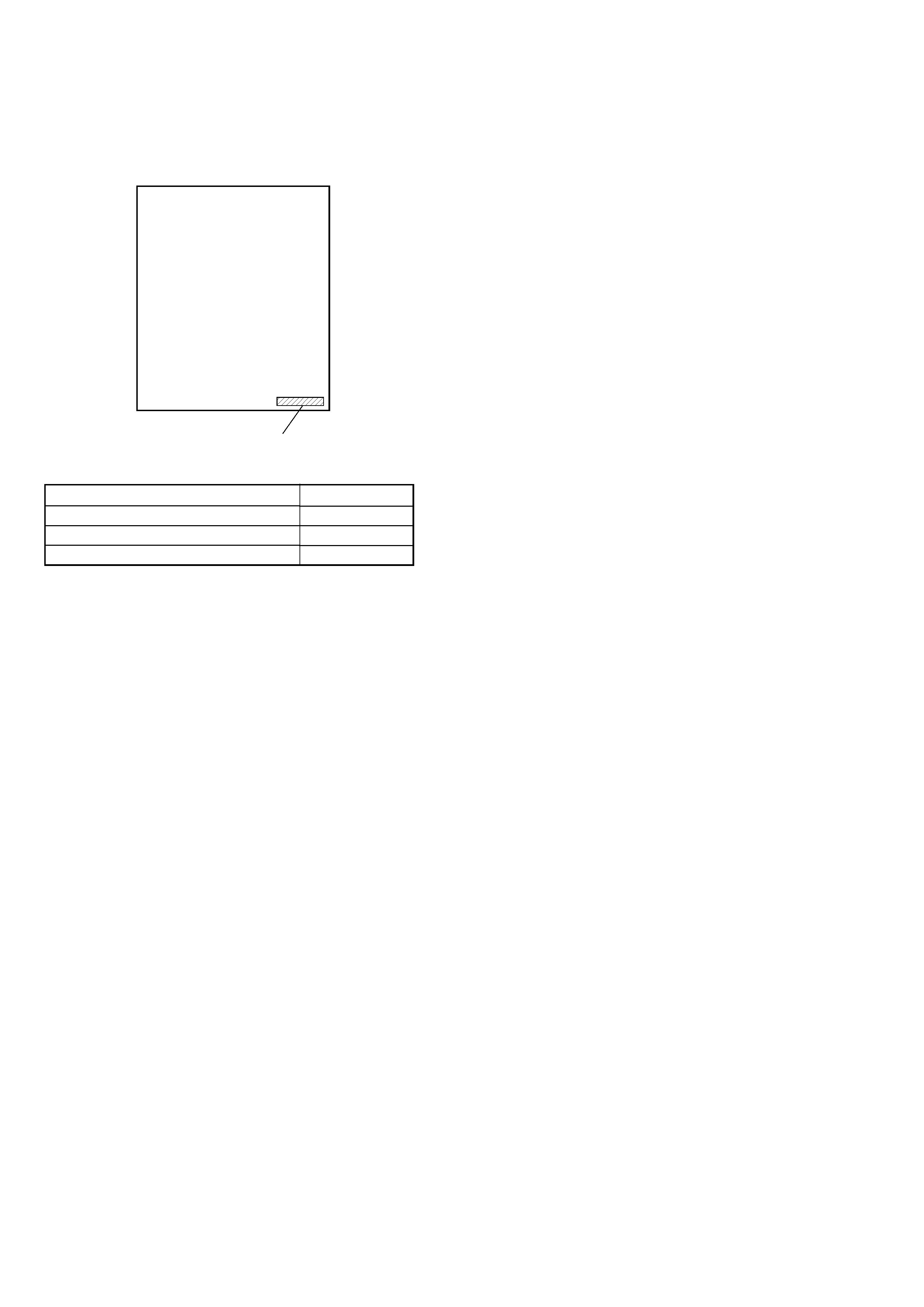
MODEL IDENTIFICATION
-- REAR PANEL --
· Abbreviation
AUS : Australian model.
CND : Canadian model.
SP
: Singapore model.
MY : Malaysia model.
TW : Taiwan model.
KR
: Korean model.
E51 : Chilean and Peruvian models.
MX : Mexican model.
Parts No.
Parts No.
4-245-014-1s
4-245-014-3s
4-245-014-4s
Model Destination
US, CND, AEP, UK
E51, AUS, MX, TW, KR
SP, MY
3
CX-LEM200
SECTION 1
SERVICING NOTES
SAFETY-RELATED COMPONENT WARNING!!
COMPONENTS IDENTIFIED BY MARK 0 OR DOTTED LINE WITH
MARK 0 ON THE SCHEMATIC DIAGRAMS AND IN THE PARTS
LIST ARE CRITICAL TO SAFE OPERATION. REPLACE THESE
COMPONENTS WITH SONY PARTS WHOSE PART NUMBERS
APPEAR AS SHOWN IN THIS MANUAL OR IN SUPPLEMENTS
PUBLISHED BY SONY.
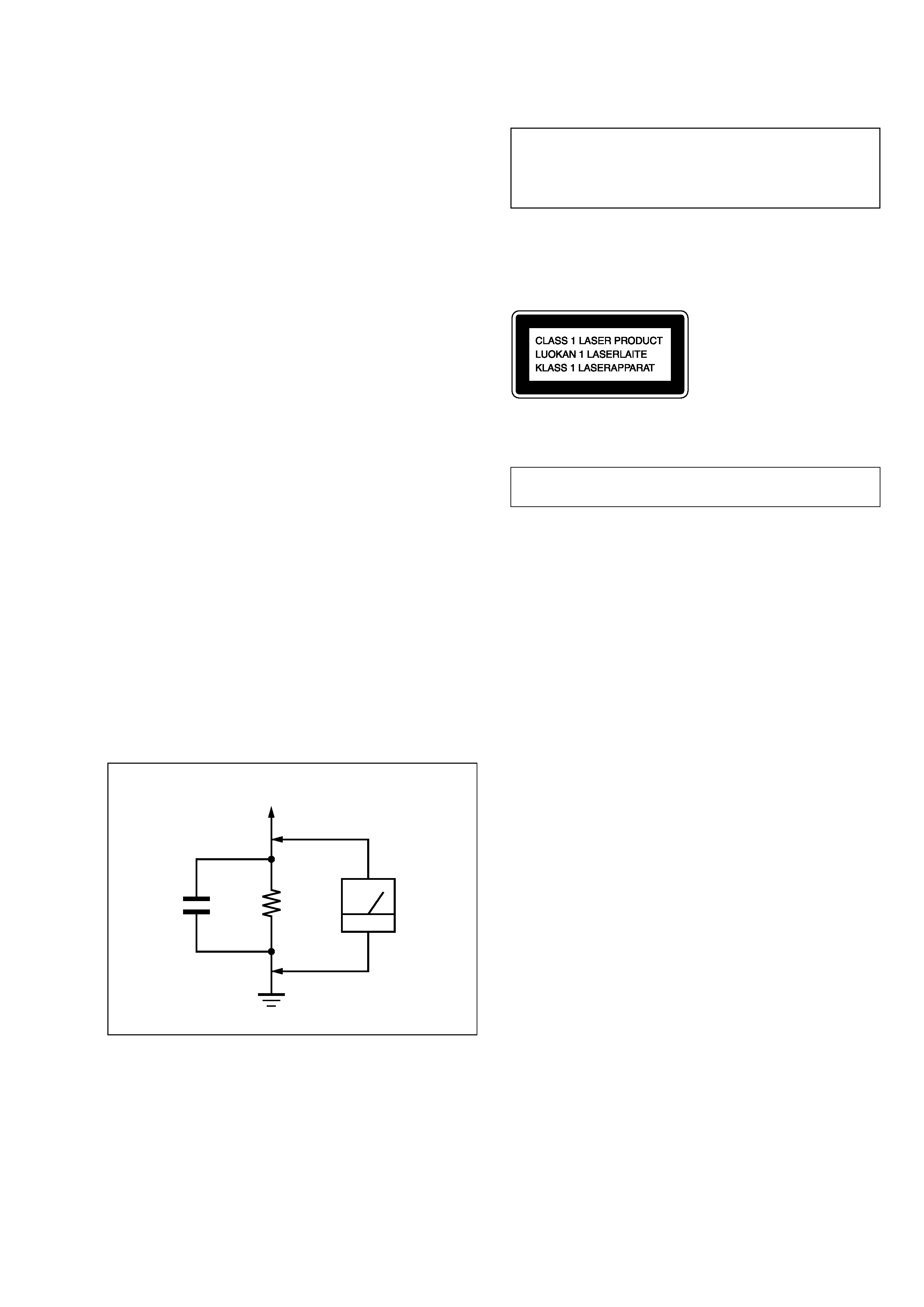
Fig. A.
Using an AC voltmeter to check AC leakage.
1.5 k
0.15
µF
AC
voltmeter
(0.75 V)
To Exposed Metal
Parts on Set
Earth Ground
SAFETY CHECK-OUT
After correcting the original service problem, perform the following
safety check before releasing the set to the customer:
Check the antenna terminals, metal trim, "metallized" knobs, screws,
and all other exposed metal parts for AC leakage.
Check leakage as described below.
LEAKAGE TEST
The AC leakage from any exposed metal part to earth ground and
from all exposed metal parts to any exposed metal part having a
return to chassis, must not exceed 0.5 mA (500 microamperes.).
Leakage current can be measured by any one of three methods.
1. A commercial leakage tester, such as the Simpson 229 or RCA
WT-540A. Follow the manufacturers' instructions to use these
instruments.
2. A battery-operated AC milliammeter. The Data Precision 245
digital multimeter is suitable for this job.
3. Measuring the voltage drop across a resistor by means of a VOM
or battery-operated AC voltmeter. The "limit" indication is 0.75
V, so analog meters must have an accurate low-voltage scale.
The Simpson 250 and Sanwa SH-63Trd are examples of a
passive VOM that is suitable. Nearly all battery operated digital
multimeters that have a 2 V AC range are suitable. (See Fig. A)
CAUTION
Use of controls or adjustments or performance of procedures
other than those specified herein may result in hazardous
radiation exposure.
This appliance is classified as a CLASS 1 LASER product.
This label is located on the exterior.
Laser component in this product is capable of emitting radiation
exceeding the limit for Class 1.
The laser diode in the optical pick-up block may suffer electrostatic
break-down because of the potential difference generated by the
charged electrostatic load, etc. on clothing and the human body.
During repair, pay attention to electrostatic break-down and also
use the procedure in the printed matter which is included in the
repair parts.
The flexible board is easily damaged and should be handled with
care.
NOTES ON LASER DIODE EMISSION CHECK
The laser beam on this model is concentrated so as to be focused on
the disc reflective surface by the objective lens in the optical pick-
up block. Therefore, when checking the laser diode emission,
observe from more than 30 cm away from the objective lens.
LASER DIODE AND FOCUS SEARCH OPERATION
CHECK
Carry out the "S curve check" in "CD section adjustment" and check
that the S curve waveforms is output three times.
NOTES ON HANDLING THE OPTICAL PICK-UP
BLOCK OR BASE UNIT
Notes on chip component replacement
·Never reuse a disconnected chip component.
· Notice that the minus side of a tantalum capacitor may be dam-
aged by heat.
Flexible Circuit Board Repairing
·Keep the temperature of the soldering iron around 270 °C during
repairing.
· Do not touch the soldering iron on the same conductor of the
circuit board (within 3 times).
· Be careful not to apply force on the conductor when soldering or
unsoldering.
ATTENTION AU COMPOSANT AYANT RAPPORT
À LA SÉCURITÉ!
LES COMPOSANTS IDENTIFÉS PAR UNE MARQUE 0 SUR LES
DIAGRAMMES SCHÉMATIQUES ET LA LISTE DES PIÈCES SONT
CRITIQUES POUR LA SÉCURITÉ DE FONCTIONNEMENT. NE
REMPLACER CES COMPOSANTS QUE PAR DES PIÈSES SONY
DONT LES NUMÉROS SONT DONNÉS DANS CE MANUEL OU
DANS LES SUPPÉMENTS PUBLIÉS PAR SONY.
Ver 1.1 2003.06
4
CX-LEM200
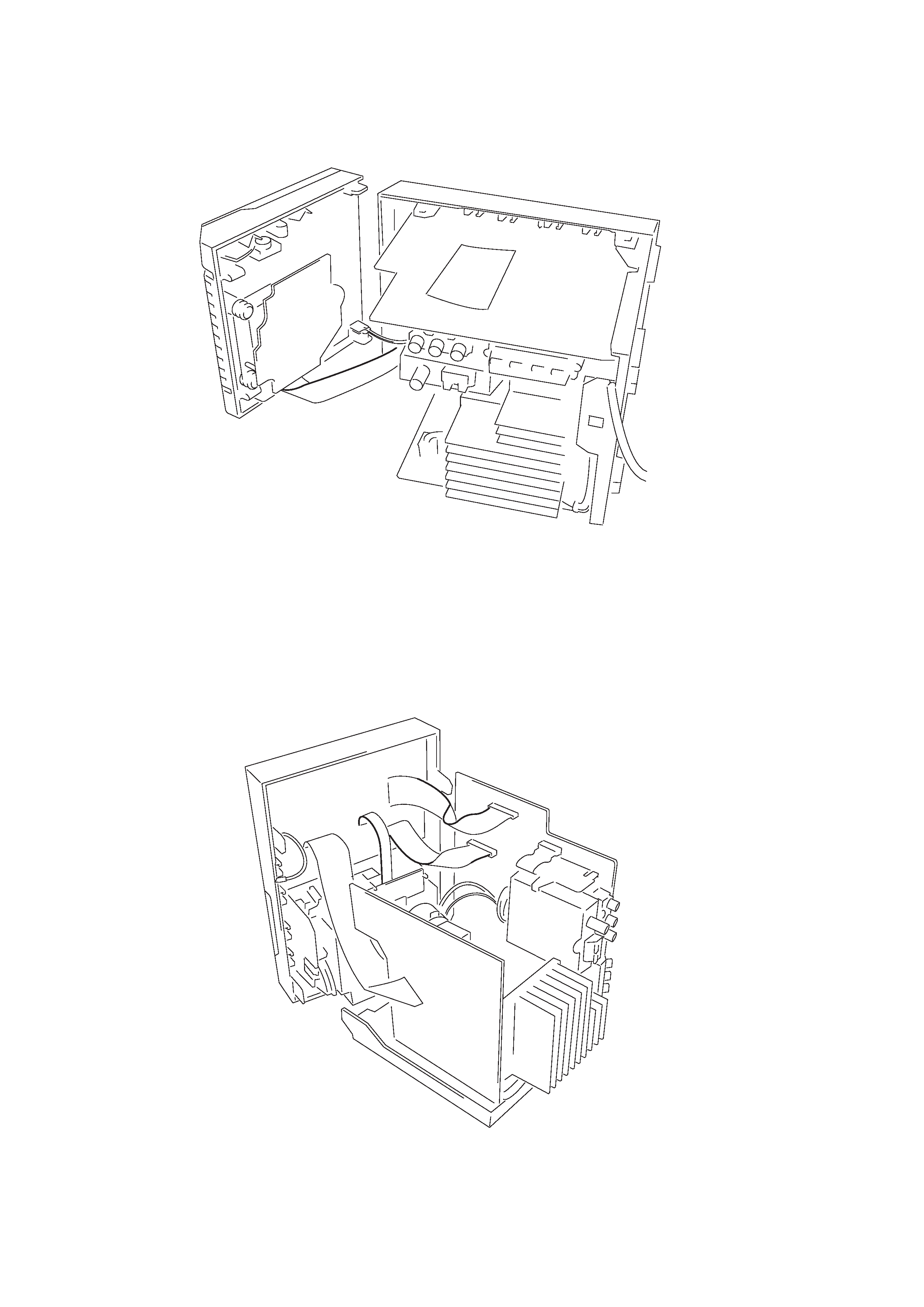
Service Position of the CD Mechanism Deck
Service Position of the Tape Cassette Mechanism Deck
5
CX-LEM200
SECTION 2
GENERAL
This section is extracted
from instruction manual.
5
En
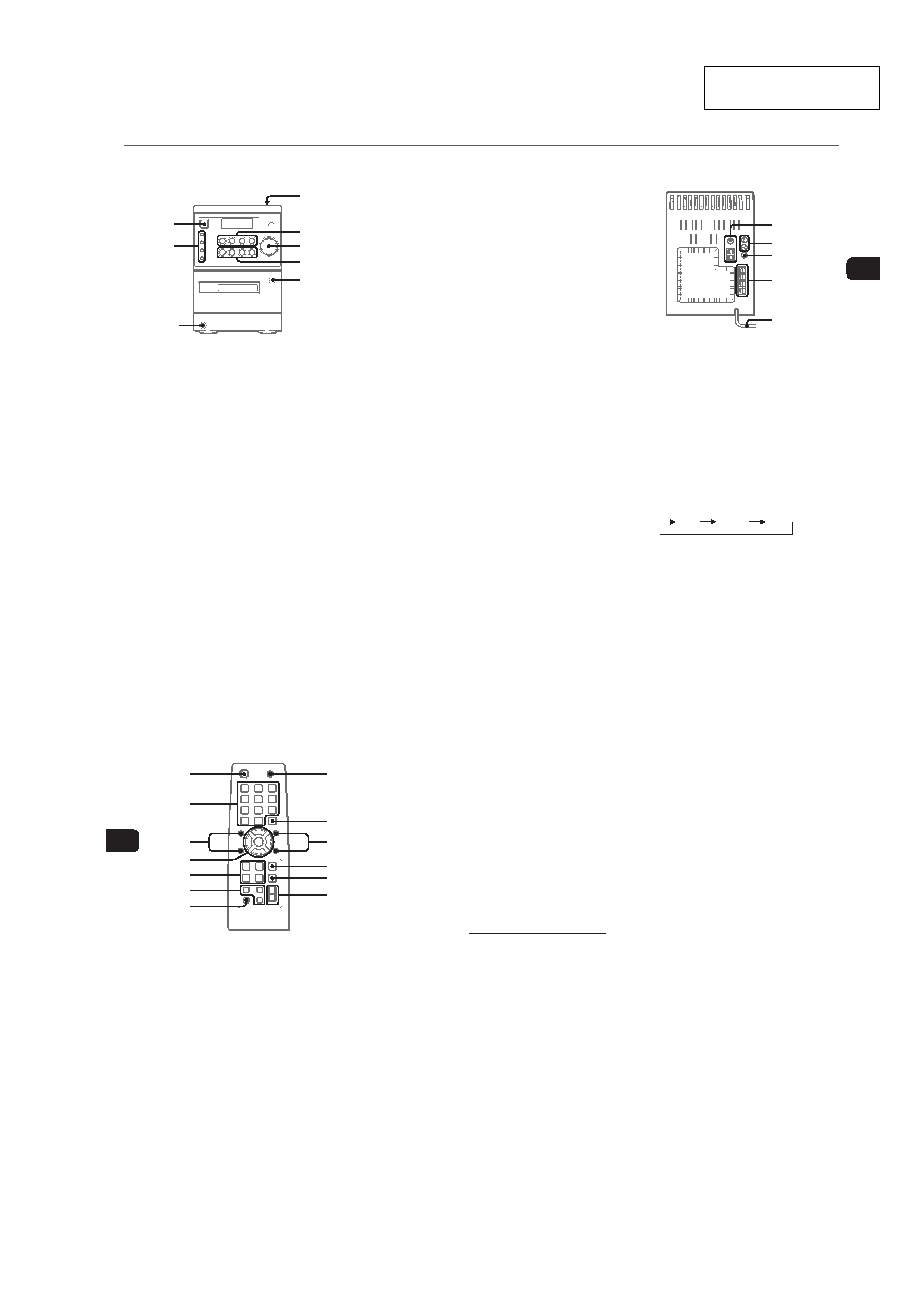
PARTS AND CONTROLS
Main unit: front
Refer to the pages indicated in parentheses for details.
1
2
6
5
4
7
3
8
1 POWER 6STANDBY/ON (7)
Switches the unit on and off (standby).
2 ECO (7)
Sets the ECO mode on or off.
SYNCHRO REC (13)
Starts recording and CD play simultaneously.
REC START/PAUSE (13)
Starts and pauses recording.
DISPLAY (8)
Changes the display in CD playback mode.
3 PHONES jack
Plug in optional headphones set with a stereo mini plug
(ø3.5 mm). Speaker output is cancelled.
4 OPEN (8)
Opens or closes the disc compartment.
5 ECD (7-9)
Starts and pauses CD play.
TUNER/BAND (7, 10)
Selects tuner function and the tuner band.
cTAPE (REC MUTING) (7, 12, 13)
Starts playback.
Also used to enter 4-second blank spaces during
recording.
AUX (7)
Selects the function of external equipment connected to
AUX IN jacks.
6 VOLUME (11, 14)
Adjusts the volume.
7 f/r-, +t/g (8, 10-12, 14, 15)
CD: skips to a previous or a succeeding track when
pressed, searches a track in fast forward or reverse
playback when held down.
Tape: rewinds or fast forwards the tape.
Tuner: manually tunes up or down within the band.
sSTOP (8, 9, 12, 13)
CD and tape: stops playback.
Tuner: clears a preset station.
TONE (11)
Adjusts the bass or treble level.
8 zPUSH EJECT (12, 13)
Opens or closes the cassette holder.
Main unit: rear
Refer to the pages indicated in parentheses for details.
3
4
5
2
1
1 AM jack and FM 75 terminal (4)
Plug in the supplied AM and FM antennas.
2 AUX IN jacks
Accept analogue sound signals from external equipment.
Connect external equipment using an optional connecting
cable with RCA phono plugs (red plug to R jack, white
plug to L jack). Refer also to the operating instructions
for your equipment.
To switch function to external input, press AUX.
To change a source name in the display of the
AUX function.
Hold down AUX and press POWER while the power is
on.
AUX
VIDEO
TV
3 SUB WOOFER jack
Connect optional powered sub woofer with a built-in
amplifier to the jack.
4 SPEAKER terminals (4)
Connect the speaker cords of the supplied speakers.
5 AC power cord (4)
6
En
Remote commander
Refer to the pages indicated in parentheses for details.
1
4
5
6
7
9
8
!
@
#
0
2
3
Buttons with the same or similar names on the main unit
basically have the same function.
1 POWER (7)
2 110/0, >10 (8-10)
CD: selects a track of the specified number.
Tuner: tunes in the station with the specified preset
number.
The numbered buttons take on these functions when pressed with
SHIFT held down:
CLOCK (7)
Selects clock mode.
TIMER (14)
Selects timer mode.
TUNER MODE (10)
Switches between stereo or monaural FM reception.
3 SHUFFLE/PROGRAM (8, 9)
Selects shuffle or programmed CD playback mode.
REPEAT (8)
Selects repeat CD playback mode.
4 PRESETN,M (10)
f/r,t/g (8, 10-12, 14, 15)
ENTER (7, 10, 14, 15)
Determines the mode.
Stores the received station to preset.
5 ECD (7-9)
TUNER/BAND (7, 10)
dTAPE (7, 12)
Starts playback but cannot change the playback side.
AUX (7)
6 DISPLAY (8)
Changes the display in CD playback mode.
DIMMER (7)
Adjusts the display window brightness.
SLEEP (14)
Selects sleep-timer mode.
7 SHIFT
Hold down when pressing a numbered button to change
its function to that printed above the number.
8 MUTING (11)
To turn off the sound temporarily.
9 CLEAR (9, 10, 15)
CD: Clears a CD program.
Tuner: Clears a preset station.
0 TREBLE (11)
Adjusts the treble level.
BASS (11)
Adjusts the bass level.
! s (8, 9, 12, 13)
@ FUNCTION (13)
Switches the active function among TAPE, TUNER, AUX
(VIDEO or TV) and CD.
# VOLUME +,- (11)