MICROFILM
SERVICE MANUAL
US Model
Canadian Model
CVX-V3
AEP Model
UK Model
CVX-V3P
COLOR VIDEO CAMERA
CVX-V3/V3P
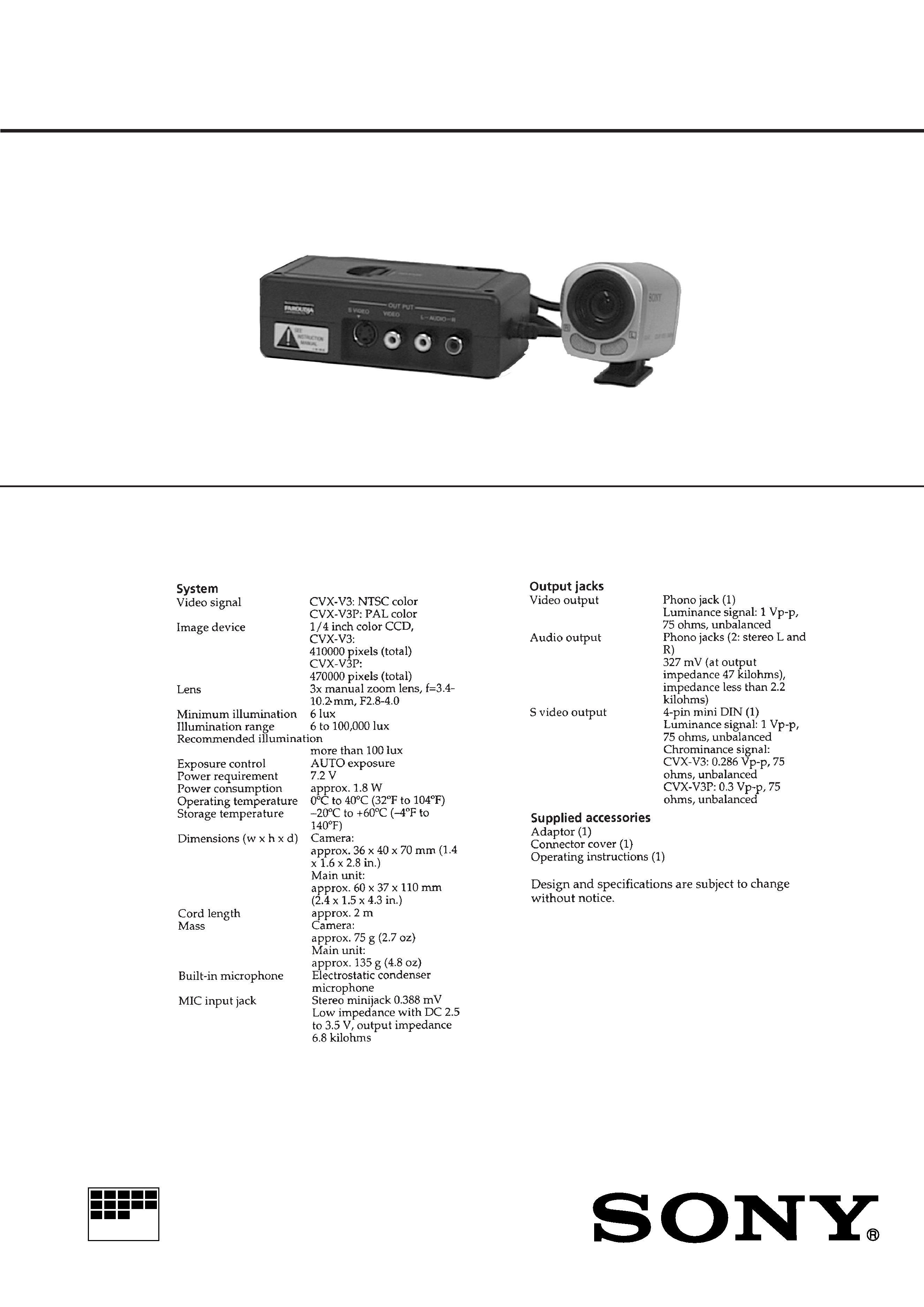
SPECIFICATIONS
NTSC model: CVX-V3
PAL model
: CVX-V3P
Photo: CVX-V3

3
1.
GENERAL ................................................................... 1-1
2.
DISASSEMBLY
2-1.
Removal of Cabinet (Lower) Assembly ........................ 2-1
2-2.
Removal of VA-103 Board ............................................. 2-1
2-3.
Removal of Camera Head Assembly,
CS-53 Board .................................................................. 2-1
2-4.
Removal of Case (B) Assembly .................................... 2-2
2-5.
Removal of Lens (CD) PC Board Assembly ................. 2-2
2-6.
Circuit Boards Location ................................................. 2-3
3.
BLOCK DIAGRAMS
3-1.
Overall Block Diagram ................................................... 3-1
3-2.
Camera (1) Block Diagram ........................................... 3-5
3-3.
Camera (2) Block Diagram ........................................... 3-9
3-4.
Audio Block Diagram ..................................................... 3-11
3-5.
Power Block Diagram .................................................... 3-13
4.
PRINTED WIRING BOARDS AND
SCHEMATIC DIAGRAMS
4-1.
Frame Schematic Diagram ............................................ 4-1
4-2.
Printed Wiring Boards and Schematic Diagrams ......... 4-5
CD-184 (CCD Imager) Schematic Diagram ................. 4-6
CD-184 (Timing Generator), (Iris Drive, Mic In)
Schematic Diagrams ..................................................... 4-7
CS-53 (Camera, Y/C Process, Mic Amp,
Mode Control) Printed Wiring Board ............................. 4-11
CS-53 (Camera, Y/C Process)
Schematic Diagram ....................................................... 4-15
CS-53 (Mode Control) Schematic Diagram .................. 4-21
CS-53 (Mic Amp) Schematic Diagram .......................... 4-23
VA-103 (DC-DC Converter, Video/Audio I/O, LANC I/O),
IF-69 (Interface) Printed Wiring Boards ........................ 4-28
VA-103 (DC-DC Converter) Schematic Diagram ......... 4-33
VA-103 (Video/Audio I/O) Schematic Diagram ............. 4-36
VA-103 (LANC I/O), IF-69 (Interface)
Schematic Diagrams ..................................................... 4-39
5.
ADJUSTMENTS
5-1.
Camera Section Adjustment ......................................... 5-1
1-1.
Preparations Before Adjustment ................................... 5-1
1-1-1. List of Service Tools ................................................. 5-1
1-1-2. Preparations ............................................................. 5-2
1-1-3. Precaution ................................................................ 5-3
1.
Setting the Switch .................................................... 5-3
2.
Order of Adjustment ................................................. 5-3
3.
Subjects .................................................................... 5-3
1-1-4. Adjustment Remote Commander ............................ 5-4
1.
Using the Adjustment Remote Commander ............ 5-4
2.
Precaution Upon Using the Adjustment
Remote Commander ................................................ 5-4
1-1-5. Data Process ............................................................ 5-5
1-2.
Initialization of F Page Data .......................................... 5-6
1.
Initializing the F Page Data ...................................... 5-6
2.
Modification of F Page Data .................................... 5-6
3.
F Page Table ............................................................. 5-6
1-3.
Camera System Adjustments .................................. 5-9
1.
28 MHz Origin Oscillation Adjustment ..................... 5-9
2.
HALL Adjustment ..................................................... 5-10
3.
Picture Frame Setting .............................................. 5-11
4.
Color Reproduction Adjustment ............................... 5-12
5.
IRIS IN/OUT Adjustment .......................................... 5-13
6.
Auto White Balance Reference Data Input .............. 5-14
7.
Auto White Balance Adjustment .............................. 5-14
8.
White Balance Check ............................................... 5-15
9.
Battery Down Adjustment ........................................ 5-16
6.
REPAIR PARTS LIST
6-1.
Exploded Views ............................................................. 6-1
6-1-1. Main Section ............................................................. 6-1
6-1-2. Camera Head Section .............................................. 6-2
6-2.
Electrical Parts List ....................................................... 6-3
TABLE OF CONTENTS
Section
Title
Page
Section
Title
Page
* The color reproduction frame is shown after the page
of ELECTRICAL PARTS LIST.
2-1
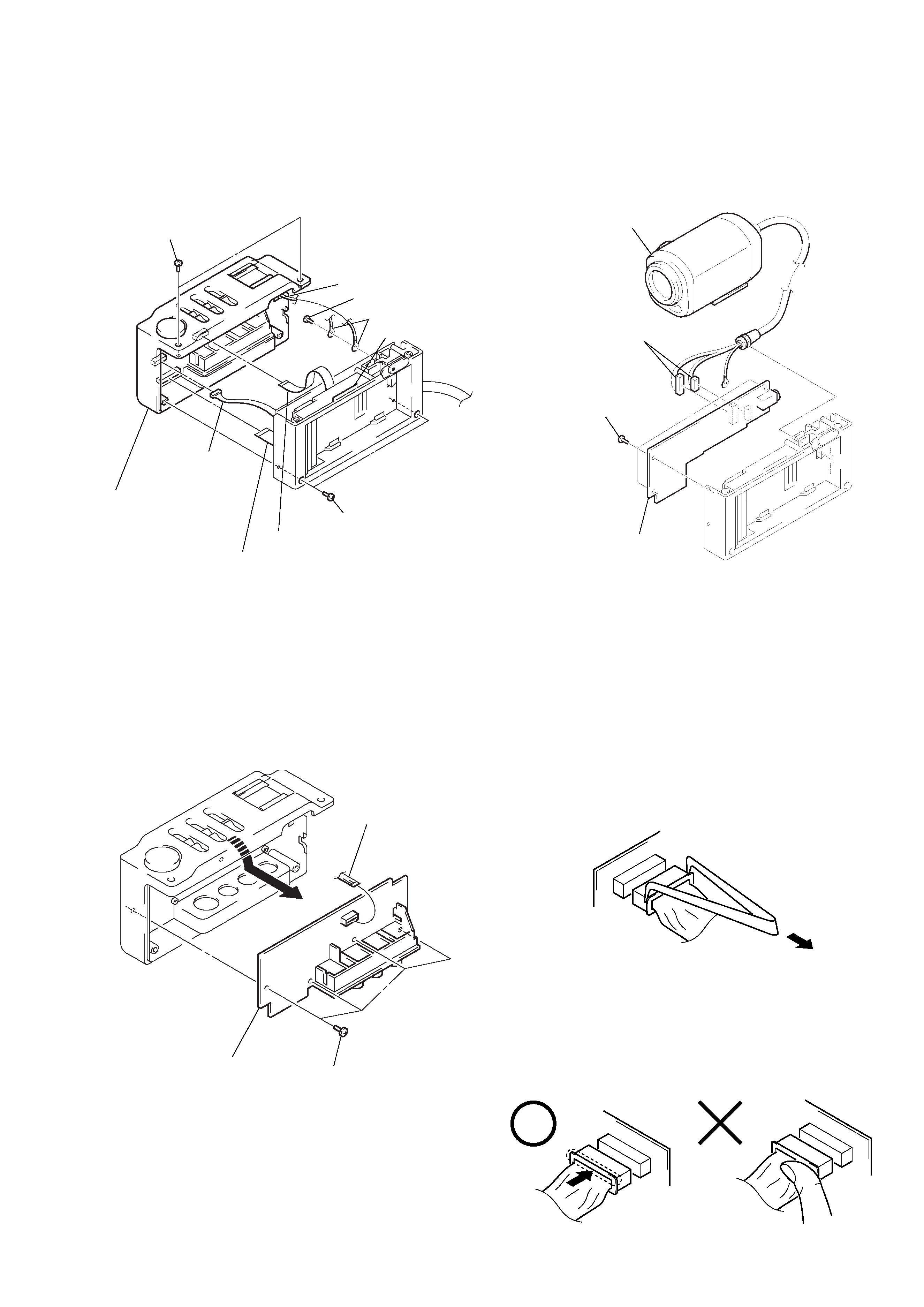
Note: Follow the disassembly procedure in the numerical order given.
2-1. REMOVAL OF CABINET (LOWER)
ASSEMBLY
2-3. REMOVAL OF CAMERA HEAD
ASSEMBLY, CS-53 BOARD
2-2. REMOVAL OF VA-103 BOARD
SECTION 2
DISASSEMBLY
CVX-V3/V3P
1 Two tapping
screws
3 Claw
9 Tapping screw
0 Two earth leads
4 Claw
2 Two tapping screws
6 Connector
(CN601)
5 Cabinet (lower)
assembly
8 Flexible flat cable (CN802)
7 Flexible flat cable (CN801)
CS-53
Board
2 Camera head assembly
1 Two connectors
(CN301, 302)
(Note1, 2)
3 Three tapping
screws
4 CS-53 board
VA-103
Board
1 Flexible board
(CN803)
2 Four tapping screws
3 VA-103 board
Note 1: When remove a connector, don't pull at
wire of connector.
Be in danger of the snapping of a wire.
Note 2: When installing a connector, don't press
down at wire of connector.
Be in danger of the snapping of a wire.