1
SERVICE MANUAL
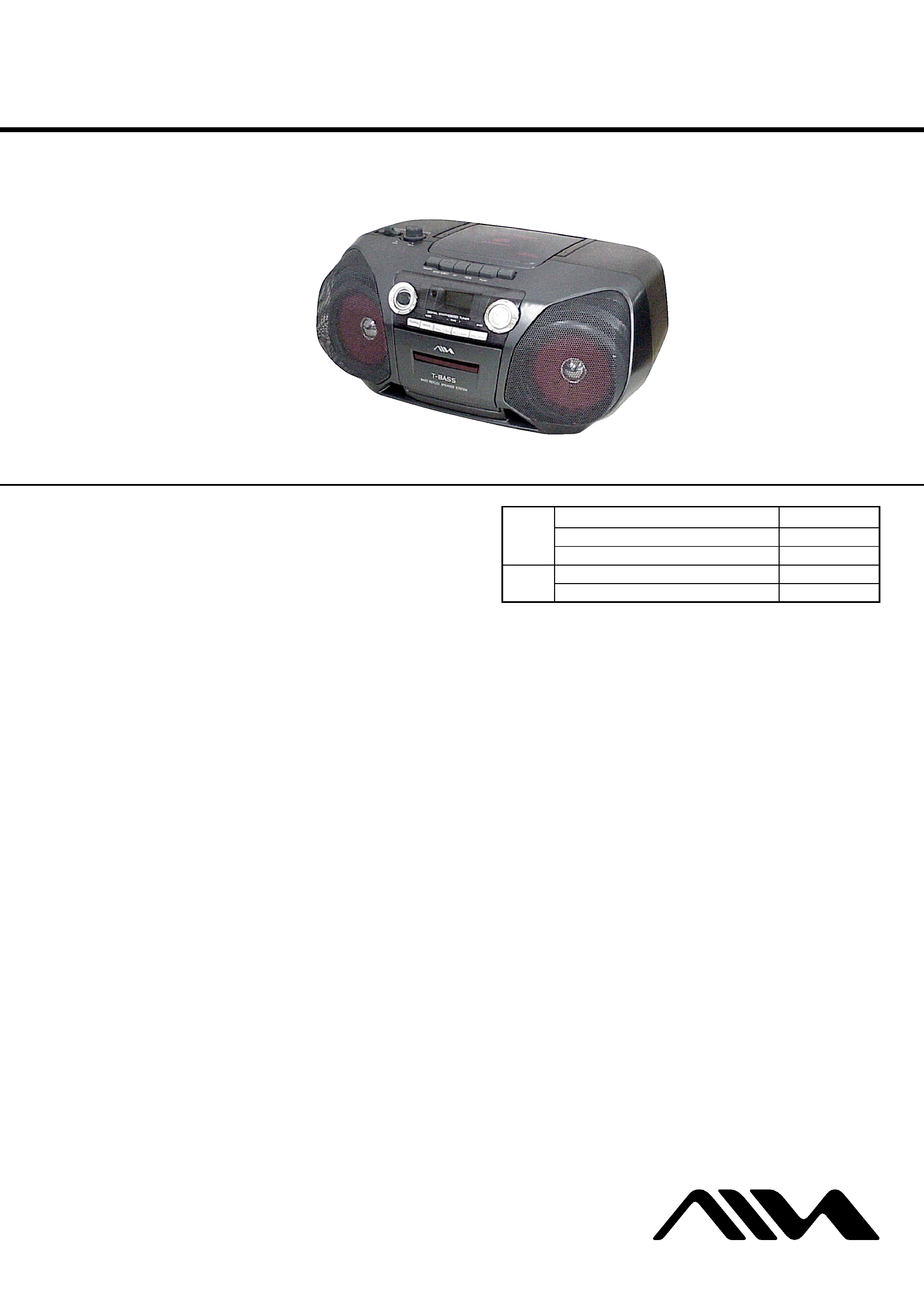
CSD-TD10/TD30
CD STEREO RADIO CASSETTE RECORDER
Radio section
Frequency range, antenna
FM: 87.5 - 108.0 MHz Rod antenna
US, CND, E4 model:
AM: 530/531 - 1,710/1,602 kHz (10/9 kHz step)
Ferrite bar antenna
AEP, UK model:
AM: 531/530 - 1,602/1,610 kHz (9/10 kHz step)
Ferrite bar antenna
MX model:
AM: 530/531 - 1,710/1,610 kHz (10/9 kHz step)
Ferrite bar antenna
Deck section
Track format
4 tracks, 2 channels
Frequency range
Normal tape: 50 - 12,500 Hz (JEITA)
Recording system
AC bias
Erasing system
Magnet erase
Heads
Recording/playback head (1)
Erasure head (1)
SPECIFICATIONS
CD player section
Disc
Compact disc
Scanning method
Non-contact optical scanner (semiconductor laser)
Laser diode properties
Material: GaAlAs
Wavelength:
= 780 nm
Emission duration: Continuous
Laser output: Less than 44.6 µW
(This output is the value measured at a distance of
200 mm from the objective lens surface on the
optical pick-up block with 7 mm aperture.)
General
Speaker
100 mm cone type (2)
Power output
AEP model:
3.4 W + 3.4 W (DIN MUSIC POWER)
2 W + 2 W (JEITA 8 ohms, T.H.D. 10% DC)
AEP, UK, E4, MX model:
1 W + 1 W (DIN 1% Rated Power)
Ver 1.0 2003. 07
9-961-070-01
2003G04-1
© 2003. 07
US Model
AEP Model
UK Model
E Model
Australian Model
CSD-TD10/TD30
Canadian Model
CSD-TD10
CD
Model Name Using Similar Mechanism CSD-A300
Section
CD Mechanism Type
KSM-213RDM
Optical Pick-up Name
KSS-213R
TC
Model Name Using Similar Mechanism NEW
Section Tape Transport Mechanism Type
MF-TD10
Sony Corporation
Personal Audio Company
Published by Sony Engineering Corporation
Photo: CSD-TD30
Continued on next page
2
CSD-TD10/TD30
SAFETY-RELATED COMPONENT WARNING!!
COMPONENTS IDENTIFIED BY MARK 0 OR DOTTED LINE
WITH MARK 0 ON THE SCHEMATIC DIAGRAMS AND IN
THE PARTS LIST ARE CRITICAL TO SAFE OPERATION.
REPLACE THESE COMPONENTS WITH SONY PARTS WHOSE
PART NUMBERS APPEAR AS SHOWN IN THIS MANUAL OR
IN SUPPLEMENTS PUBLISHED BY SONY.
CAUTION
Use of controls or adjustments or performance of proce-
dures other than those specified herein may result in haz-
ardous radiation exposure.
Flexible Circuit Board Repairing
· Keep the temperature of the soldering iron around 270°C during
repairing.
· Do not touch the soldering iron on the same conductor of the
circuit board (within 3 times).
· Be careful not to apply force on the conductor when soldering
or unsoldering.
Notes on Chip Component Replacement
· Never reuse a disconnected chip component.
· Notice that the minus side of a tantalum capacitor may be dam-
aged by heat.
NOTES ON HANDLING THE OPTICAL PICK-UP BLOCK
OR BASE UNIT
The laser diode in the optical pick-up block may suffer electrostatic
breakdown because of the potential difference generated by the
charged electrostatic load, etc. on clothing and the human body.
During repair, pay attention to electrostatic breakdown and also use
the procedure in the printed matter which is included in the repair
parts.
The flexible board is easily damaged and should be handled with
care.
NOTES ON LASER DIODE EMISSION CHECK
The laser beam on this model is concentrated so as to be focused on
the disc reflective surface by the objective lens in the optical pick-
up block. Therefore, when checking the laser diode emission,
observe from more than 30 cm away from the objective lens.
ATTENTION AU COMPOSANT AYANT RAPPORT
À LA SÉCURITÉ!!
LES COMPOSANTS IDENTIFIÉS PAR UNE MARQUE 0 SUR LES
DIAGRAMMES SCHÉMATIQUES ET LA LISTE DES PIÈCES SONT
CRITIQUES POUR LA SÉCURITÉ DE FONCTIONNEMENT. NE
REMPLACER CES COMPOSANTS QUE PAR DES PIÈCES SONY
DONT LES NUMÉROS SONT DONNÉS DANS CE MANUEL OU
DANS LES SUPPLÉMENTS PUBLIÉS PAR SONY.
This Compact Disc player is classified as a CLASS 1
LASER product.
The CLASS 1 LASER PRODUCT label is located on the
exterior.
AEP, UK, E, AUS model
Power requirements
DC 12 V using eight size C (R14) batteries
US, CND, MX model:
AC 120 V, 60 Hz
AEP, UK model:
AC 230 V, 50 Hz
E4 model:
AC 110 V - 120 V/220 - 240 V switchable, 50/60 Hz
Power consumption
US, CND model:
12 W
AEP, UK, E4, MX model:
13 W
Dimensions (W
× H × D)
390
× 170 × 258.5 mm
(15 3/8
× 6 3/4 × 10 1/4 in.)
Weight (excluding batteries)
2.7 kg (5 lbs. 15 oz.)
Accessory
Remote control (1, CSD-TD30 only)
AC cord (1)
Specifications and external appearance are subject to
change without notice.
·Abbreviation
CND
: Canadian model
E4
: AC 110-120V/220-240V area in E model
MX
: Mexican model
TW
: Taiwan model
AUS: Australian model
SP
: Singapore model
KR
: Korean model
CLASS 1
KLASSE 1
LUOKAN 1
KLASS 1
LASER
LASER
LASER
LASER
PRODUCT
PRODUKT
LAITE
APPARAT

3
TABLE OF CONTENTS
1. SERVICING NOTES ......................................................... 4
2. GENERAL ............................................................................ 5
3. DISASSEMBLY
3-1. CABI Rear Assy .................................................................. 7
3-2. CABI Top Assy ................................................................... 7
3-3. CD Block Assy .................................................................... 8
3-4. Main Board ......................................................................... 8
3-5. Tape Mechanism Deck ........................................................ 9
3-6. CASS Door Assy ................................................................. 9
3-7. Display Board ................................................................... 10
3-8. HRP001, HE001, Pinch Roller Arm Assy ......................... 10
3-9. Belt, M501 ........................................................................ 11
3-10. Optical Pick-up ................................................................. 11
4. MECHANICAL ADJUSTMENTS ............................... 12
5. ELECTRICAL ADJUSTMENTS
Tape Section .......................................................................... 13
Tuner Section ......................................................................... 14
CD Section ............................................................................ 15
6. DIAGRAMS
6-1. IC Pin Description ............................................................. 17
6-2. Block Diagram CD Section ......................................... 19
6-3. Block Diagram Tuner Section ..................................... 20
6-4. Block Diagram Tape Section ....................................... 21
6-5. Circuit Boards Location .................................................... 22
6-6. Printed Wiring Board Main Section ............................ 23
6-7. Schematic Diagram CD Section .................................. 24
6-8. Schematic Diagram Tuner Section .............................. 25
6-9. Schematic Diagram Tape Section ............................... 26
6-10. Printed Wiring Board TC Section ............................... 27
6-11. Printed Wiring Boards
Control, Power Supply Section .................................. 28
6-12. Schematic Diagram Control, Power Supply Section .. 29
6-13. IC Block Diagrams ............................................................ 30
7. EXPLODED VIEWS
7-1. Main Board Section .......................................................... 32
7-2. Cabinet Front (1) Section .................................................. 33
7-3. Cabinet Front (2) Section .................................................. 34
7-4. Chassis CD Section ........................................................... 35
7-5. Cabinet Rear Section ......................................................... 36
7-6. Tape Mechanism Section .................................................. 37
7-7. CD Mechanism Section .................................................... 38
8. ELECTRICAL PARTS LIST ......................................... 39
CSD-TD10/TD30
4
CSD-TD10/TD30
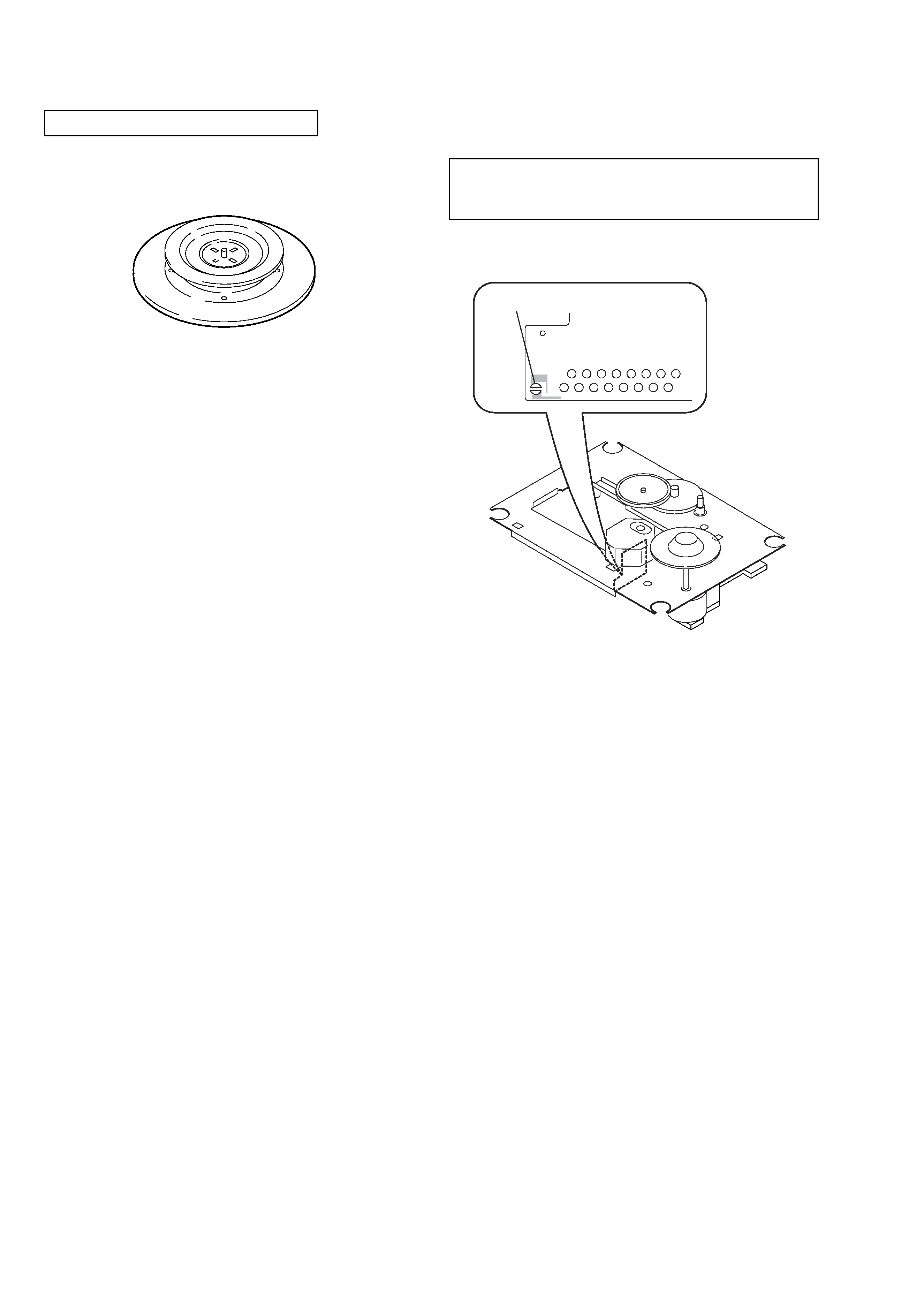
CHUCK PLATE JIG ON REPAIRING
On repairing CD section, playing a disc without the lid (CD), use
Chuck Plate Jig.
· Code number of Chuck Plate Jig: X-4918-255-1
SECTION 1
SERVICING NOTES
PRECAUTION TO REPLACE OPTICAL BLOCK
(KSM-213RDM)
solder
Body or clothes electrostatic potential could ruin laser diode
in the optical block. Be sure ground body and workbench,
and use care the clothes do not touch the diode.
1) After the connection, remove solder shown in the right figure.
5
CSD-TD10/TD30
SECTION 2
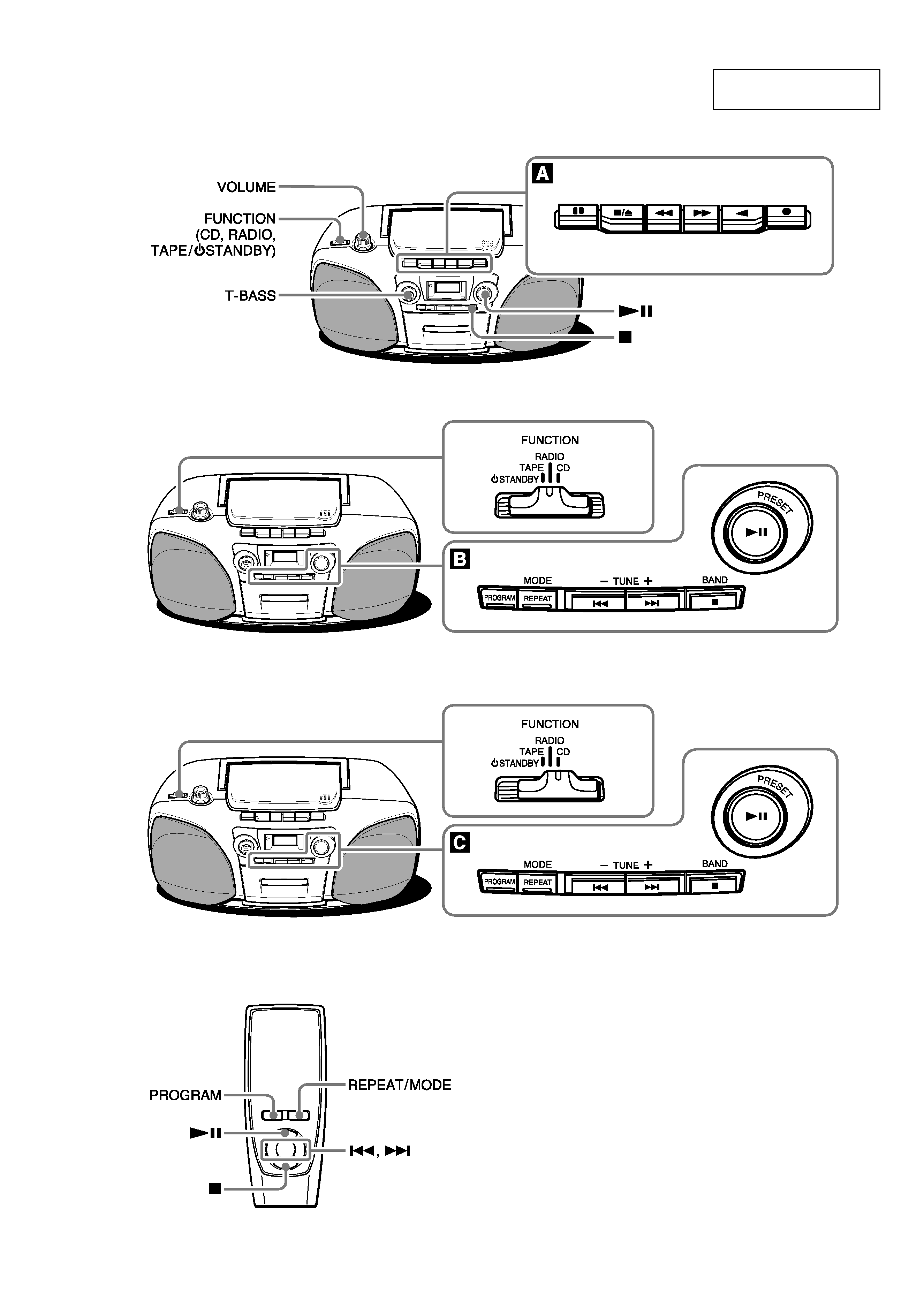
GENERAL
This section is extracted
from instruction manual.
PAUSE
STOP/EJECT
FF
REW
PLAY
REC
(CSD-TD30 only)