
Design and specifications are subject to change without notice.
TRINITRON® COLOR MONITOR
SERVICE MANUAL
21CR1 CHASSIS
AEP Model
Chassis No: SCC-L33T-A
CPD-E530
9-878-801-01
ORIGINAL MANUAL ISSUE DATE: 1/2003
ALL REVISIONS AND UPDATES TO THE ORIGINAL MANUAL ARE APPENDED TO THE END OF THE PDF FILE.
REVISION DATE
REVISION TYPE
SUBJECT
1/2003
No revisions or updates are applicable at this time.
HISTORY INFORMATION FOR THE FOLLOWING MANUAL:
Design and specifications are subject to change without notice.
TRINITRON® COLOR MONITOR
SERVICE MANUAL
21CR1 CHASSIS
AEP Model
Chassis No: SCC-L33T-A
CPD-E530
9-878-801-01
Picture tube
0.24 mm aperture grill pitch (center)
21 inches measured diagonally
90-degree deflection
FD Trinitron
Video image area
19.8" viewing image
Approx. 403.8 X 302.2 mm (w/h)
(16 x 12 inches)
Resolution
*Recommended
Addressable:
Horizontal: Max. 1600 dots
Vertical: Max. 1200 lines
Standard image area Approx. 388 x 291 mm (w/h)
(153/8 x 111/2 inches)
or
Approx. 364 x 291 mm (w/h)
(143/8 x 111/2 inches)
Input signal
Video
Analog RGB (75 ohms typical)
0.700 Vp-p Positive
Sync
H/V Separate or Composite sync
TTL 2 k ohms, Polarity free
Sync on Green:
0.3 Vp-p Negative
Power consumption
135 W
Deflection frequency* Horizontal: 30 kHz to 117 kHz
Vertical:
48 kHz to 170 kHz
AC input voltage/current 100V to 240V, 50 - 60Hz,
2.0 - 1.0A
Dimensions
497 x 502 x 485 mm (w/h/d)
(195/8 x 19 x 187/8 inches)
Mass
Approx. 30 kg (66 lb 2 oz.)
Plug and Play
DDC2B/DDC2Bi, GTF**
*
Recommended horizontal and vertical timing condition
Horizontal sync width duty should be more than 4.8% of
total horizontal time or 0.8 µs, whichever is larger.
Horizontal blanking width should be more than 2.3 µsec.
Vertical blanking width should be more than 450 µsec.
** If the input signal is Generalized Timing Formula (GTF)
compliant, the GTF feature of the monitor will automatically
provide an optimal image for the screen.
SPECIFICATIONS
Self Diagnosis
Supported model

-- 3 --
CPD-E530
TABLE OF CONTENTS
SECTION TITLE
PAGE
Power Management .................................................................................................................................. 4
Diagnosis Function.................................................................................................................................... 4
Timing Specification .................................................................................................................................. 5
Warnings and Cautions............................................................................................................................. 6
Safety Check-Out...................................................................................................................................... 7
SECTION 1: DISASSEMBLY.................................................................................................................................. 8
1-1. Cabinet Removal............................................................................................................................. 8
1-2. Service Position............................................................................................................................... 9
1-3. A1 Board (C Block) Removal ........................................................................................................ 10
1-4. A1 Board Removal ........................................................................................................................ 10
1-5. Bezel Assembly and H1 Board Removal........................................................................................11
1-6. D Board Removal .......................................................................................................................... 12
1-7. Picture Tube Removal ................................................................................................................... 13
Anode Cap Removal ..................................................................................................................... 13
1-8. Harness Location .......................................................................................................................... 14
SECTION 2: SAFETY RELATED ADJUSTMENTS.............................................................................................. 15
2-1. HV Regulator Circuit Check .......................................................................................................... 15
2-2. HV Protector Circuit Check............................................................................................................ 15
2-3. Beam Current Protector Circuit Check .......................................................................................... 15
SECTION 3: ADJUSTMENTS .............................................................................................................................. 16
3-1. Landing Rough Adjustment ........................................................................................................... 16
3-2. Landing Fine Adjustment............................................................................................................... 16
3-3. Convergence Rough Adjustment................................................................................................... 17
3-4. White Balance Adjustment Specification ....................................................................................... 17
3-5. Vertical and Horizontal Position and Size Specification ................................................................ 18
3-6. Focus Adjustment.......................................................................................................................... 18
SECTION 4: DIAGRAMS...................................................................................................................................... 19
4-1. Circuit Boards Location ................................................................................................................. 19
4-2. Printed Wiring Board and Schematic Diagram Information........................................................... 19
4-3. Block Diagrams ............................................................................................................................. 20
A1 Block Diagram, H1 Block Diagram, and L2 Block Diagram ..................................................... 20
DA Block Diagram and N Block Diagram ...................................................................................... 21
D Block Diagram ........................................................................................................................... 22
4-4. Schematics and Supporting Information ....................................................................................... 23
H1 Board Schematic Diagram....................................................................................................... 23
A1 Board Schematic Diagram ....................................................................................................... 24
D Board Schematic Diagram......................................................................................................... 26
DA Board Schematic Diagram....................................................................................................... 28
N Board Schematic Diagram......................................................................................................... 29
L2 Board Schematic Diagram ....................................................................................................... 30
4-5. Semiconductors............................................................................................................................. 31
SECTION 5: EXPLODED VIEW ........................................................................................................................... 33
5-1. Chassis.......................................................................................................................................... 33
5-2. Picture Tube .................................................................................................................................. 34
5-3. Packing Materials .......................................................................................................................... 35
SECTION 6: ELECTRICAL PARTS LIST............................................................................................................ 36
-- 4 --
CPD-E530
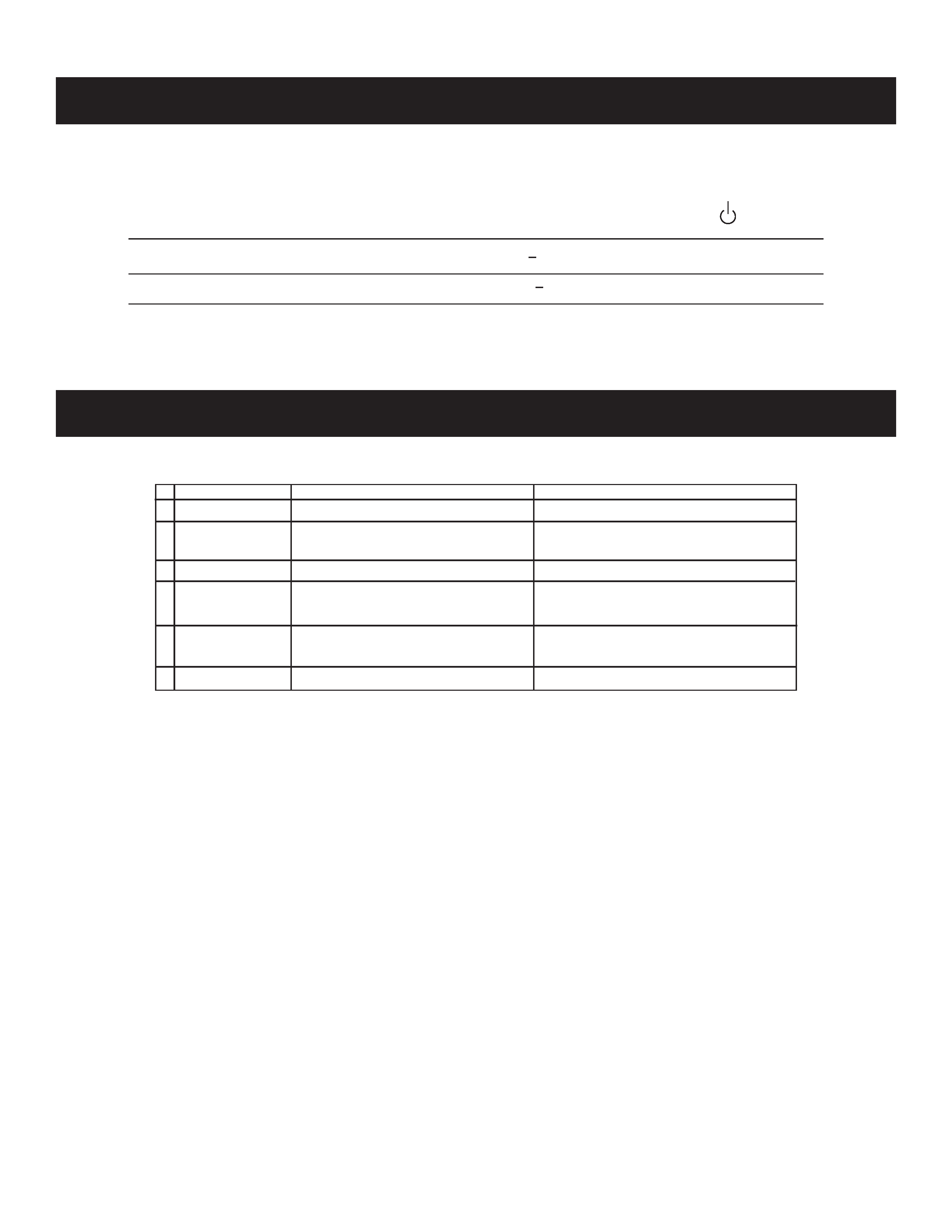
POWER MANAGEMENT
The power saving mode complies with the VESA Display Power Management Signaling standard. Each state of power management shall be activated
by the host computer terminating the appropriate sync signals. Blanking the video must precede termination of the sync signals. The elapsed time
counter shall also be controlled by the host computer. Reactivation of the monitor shall be accomplished from the host computer by re-establishing the
normal sync signal.
Power consumption
Screen
Horizontal
Vertical
Power
Recovery time
Indicator
mode
(video) sync signal sync signal consumption
1
Normal operation
active
yes
yes
< 135 W
--
Green
2
Active-off* (deep sleep)** blank
no*
no*
< 3 W
Orange
3
Power-off
--
--
--
0 W (approx)
--
Off
* When your computer enters power saving mode, the input signal is cut and NO SIGNAL appears on the screen before the
monitor enters active mode. After a few seconds, the monitor enters power saving mode.
* "Deep sleep" is power saving mode defined by the Environmental Protection Agency.
DIAGNOSIS FUNCTION
When a failure occurs, the STANDBY/TIMER lamp will flash a set number of times to indicate the possible cause of the problem. If there is more than
one error, the lamp will identify the first of the problem areas.
1
2
3
5
4
Status
Area of Failure
LED Indication
Amber (0.5 second) / Off (0.5 second)
Amber (0.5 second) / Off (1.5 second)
+B
Horizontal/Vertical Deflection Failure
Thermal Protector
ABL Protector
HV Failure
Failure 1
Failure 2
Failure 3
Failure 4
Aging/Self Test
6 Out of scan range
Amber (1.5 second) / Off (0.5 second)
Green (0.5 second) / Off (0.5 second)
Green (OSD Indication)
Amber (0.25 second) / Off (0.25 second)
Amber (0.25 second) / Off (1.25 second)
Amber (0.5 second) / Off (0.5 second)
Aging Mode (Video Aging): During Power Save, press MENU button for longer than 2 seconds.
Self Test (OSD Color Bar):
During Power Save, push up Control button for longer than 2 seconds.
Reliability Check Mode:
During Power Save, push down Control button for longer than 2 seconds.
-- 5 --
CPD-E530
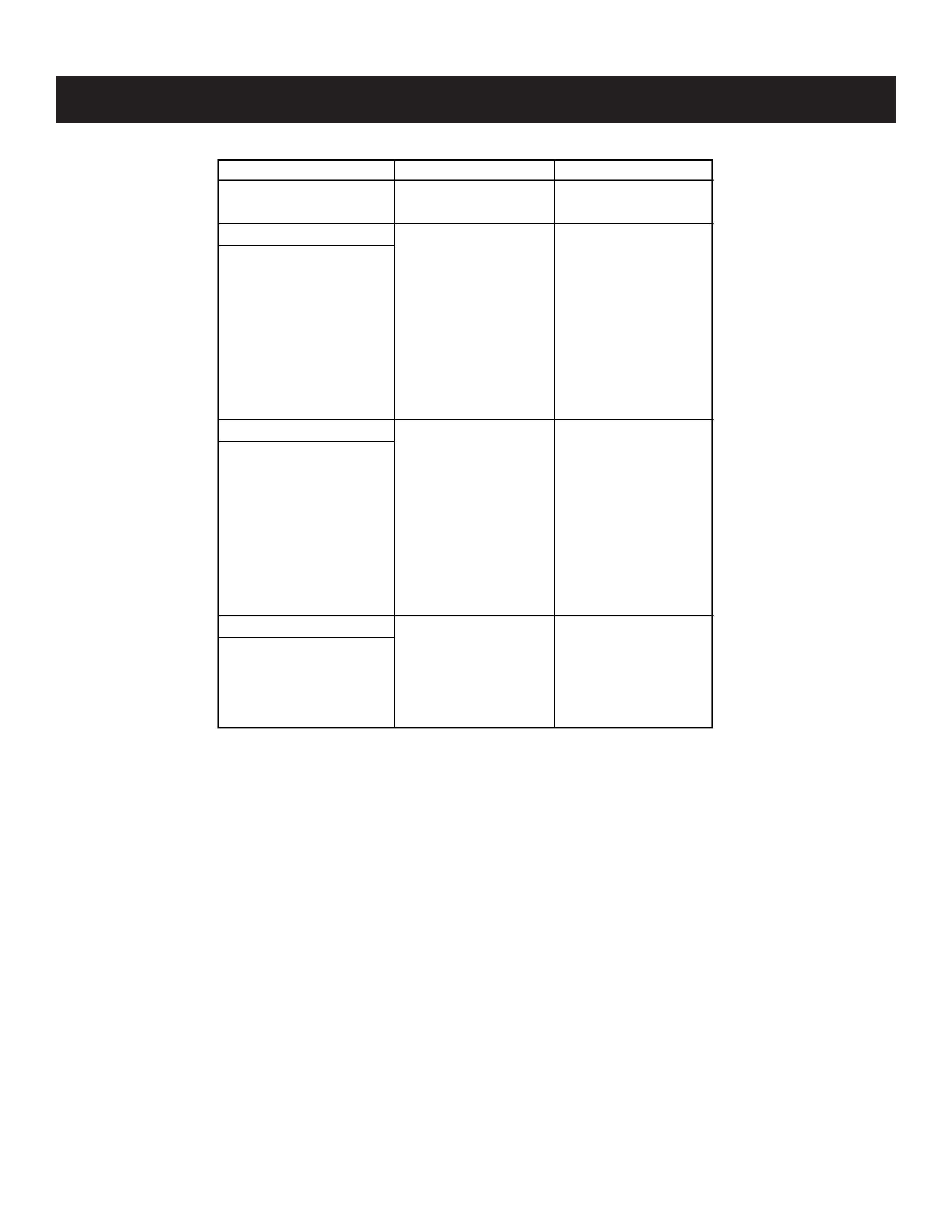
TIMING SPECIFICATION
MODE AT PRODUCTION
MODE 1
MODE 2
RESOLUTION
640 X 480
1600 X 1200
CLOCK
25.175 MHz
229.500 MHz
--HORIZONTAL--
H-FREQ
31.469 kHz
106.250 kHz
usec
usec
H. TOTAL
31.778
9.412
H. BLK
6.356
2.440
H. FP
0.636
0.279
H. SYNC
3.813
0.837
H. BP
1.907
1.325
H. ACTIV
25.422
6.972
--VERTICAL--
V. FREQ (HZ)
59.940 Hz
85.000 Hz
lines
lines
V. TOTAL
525
1250
V. BLK
45
50
V. FP
10
1
V. SYNC
2
3
V. BP
33
46
V. ACTIV
480
1200
--SYNC--
INT(G)
NO
NO
EXT (H/V) /POLARITY
YES N/N
YES P/P
EXT (CS) /POLARITY
NO
NO
INT/NON INT
NON INT
NON INT