
9-978-885-0
2
HISTORY INFORMATION FOR THE FOLLOWING MANUAL:
ORIGINAL MANUAL ISSUE DATE: 1/2002
ALL REVISIONS AND UPDATES TO THE ORIGINAL MANUAL ARE APPENDED TO THE END OF THE PDF FILE.
REVISION DATE
REVISION TYPE
SUBJECT
1/2002
No revisions or updates are applicable at this time.
2/2002
Supplement - 1
For CPD-E240(U/C) Model - Color: Black/Exploded View Parts List
SERVICE MANUAL
17VC CHASSIS
TRINITRON
® COLOR MONITOR
CPD-E240
US/Canada Model
Chassis No: SCC-L38A-A
CPD-E240
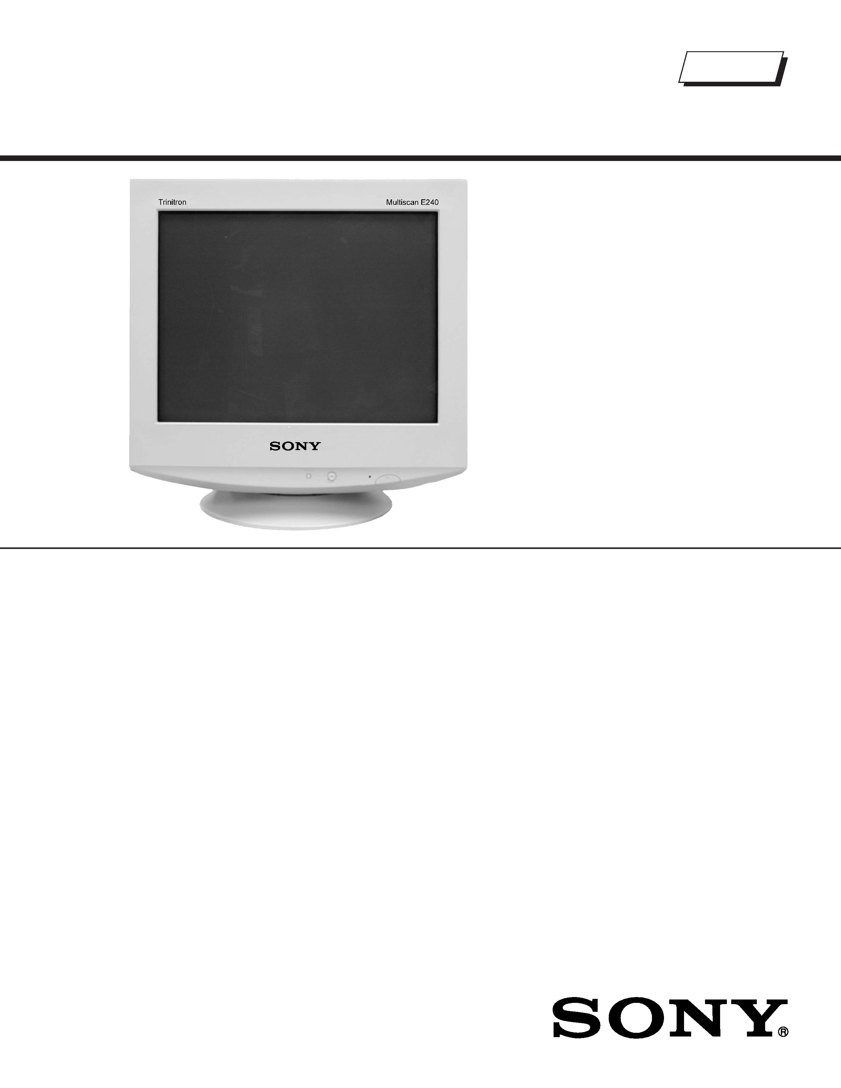
TRINITRON® COLOR MONITOR
SERVICE MANUAL
SPECIFICATIONS
17VC CHASSIS
CPD-E240
US/Canada Model
Chassis No: SCC-L38A-A
Design and specifications are subject to change without notice.
CPD-E240
Self Diagnosis
Supported model
Picture tube
0.24 mm aperture grill pitch (center)
17 inches measured diagonally
90-degree deflection
Video image area
(16.1" maximum viewing image)
Approx. 328 X 242 mm (w/h)
(13 x 9 5/8 inches)
Resolution
Horizontal: Max. 1280 dots
Vertical: Max. 1024 lines
Standard image area
Approx. 312 x 234 mm (w/h)
(12 3/8 x 9 1/4 inches)
Input signal
Video
Analog RGB (75 ohms typical)
0.7 Vp-p, ±5%, Positive
Sync
Separate HD/VD,
TTL Polarity Free
External Composite,
TTL Polarity Free (2K ohms impedance)
Sync on Green
Power Consumption
100 W
Deflection frequency
Horizontal: 30 to 75 KHz
Vertical: 48 to 120 Hz
AC input voltage/current 100 to 120 V, 50/60 Hz, 1.7A
220 to 240V, 50/60Hz, 0.9A
Dimensions
402 x 418 x 421 mm (w/h/d)
(15 7/8 x 16 1/2 x 16 5/8 inches)
Mass
Approx. 19 kg (41 lb 14 oz.)
9-978-885-0
2

-- 3 --
CPD-E240
SECTION TITLE
PAGE
Power Management.................................................................................................................................. 4
Self Diagnosis Function ............................................................................................................................ 4
Timing SpeciÞcation.................................................................................................................................. 4
Warnings and Cautions............................................................................................................................. 5
Safety Check Out Instructions .................................................................................................................. 6
1. Disassembly
1-1. Cabinet Removal ............................................................................................................................... 7
1-2. Service Position................................................................................................................................. 7
1-3. A and D Board Removal .................................................................................................................... 8
1-4. Picture Tube Removal ....................................................................................................................... 9
Anode Cap Removal ......................................................................................................................... 9
2. Safety Related Adjustments
2-1. HV Regulator Check........................................................................................................................ 10
2-2. HV Protector Circuit Check.............................................................................................................. 10
2-3. Beam Protector Check (Software Logic) ......................................................................................... 10
2-4.B+ Voltage Check............................................................................................................................. 10
3. Adjustments
3-1. Landing Rough Adjustment ..............................................................................................................11
3-2. Landing Fine Adjustment ..................................................................................................................11
3-3. Convergence Rough Adjustment......................................................................................................11
3-4. Convergence and V. Key (H. TRP) Fine Adjustment ........................................................................11
3-5. Vertical and Horizontal Position and Size SpeciÞcation .................................................................. 12
3-6. Focus Adjustment ............................................................................................................................ 12
3-7. Digital Convergence Adjustment ..................................................................................................... 13
3-8. Convergence SpeciÞcation.............................................................................................................. 13
4. Diagrams
4-1. Circuit Boards Location ................................................................................................................... 14
4-2. Schematic Diagrams And Printed Wiring Boards ............................................................................ 14
4-3. Block Diagram ................................................................................................................................. 15
A Board - Schematic Diagram......................................................................................................... 17
D Board - Schematic Diagram ........................................................................................................ 19
H1 Board - Schematic Diagram ...................................................................................................... 23
4-4. Semiconductors............................................................................................................................... 24
5. Exploded Views
5-1. Picture Tube .................................................................................................................................... 25
5-2. Chassis............................................................................................................................................ 26
5-3. Packing Materials ............................................................................................................................ 27
6. Electrical Parts List ....................................................................................................................................... 28
TABLE OF CONTENTS
-- 4 --
CPD-E240
POWER MANAGEMENT
The power saving mode complies with the VESA Display Power Management Signaling standard. Each state of power management shall be activated
by the host computer terminating the appropriate sync signals. Blanking the video must precede termination of the sync signals. The elapsed time
counter shall also be controlled by the host computer. Reactivation of the monitor shall be accomplished from the host computer by re-establishing the
normal sync signal.
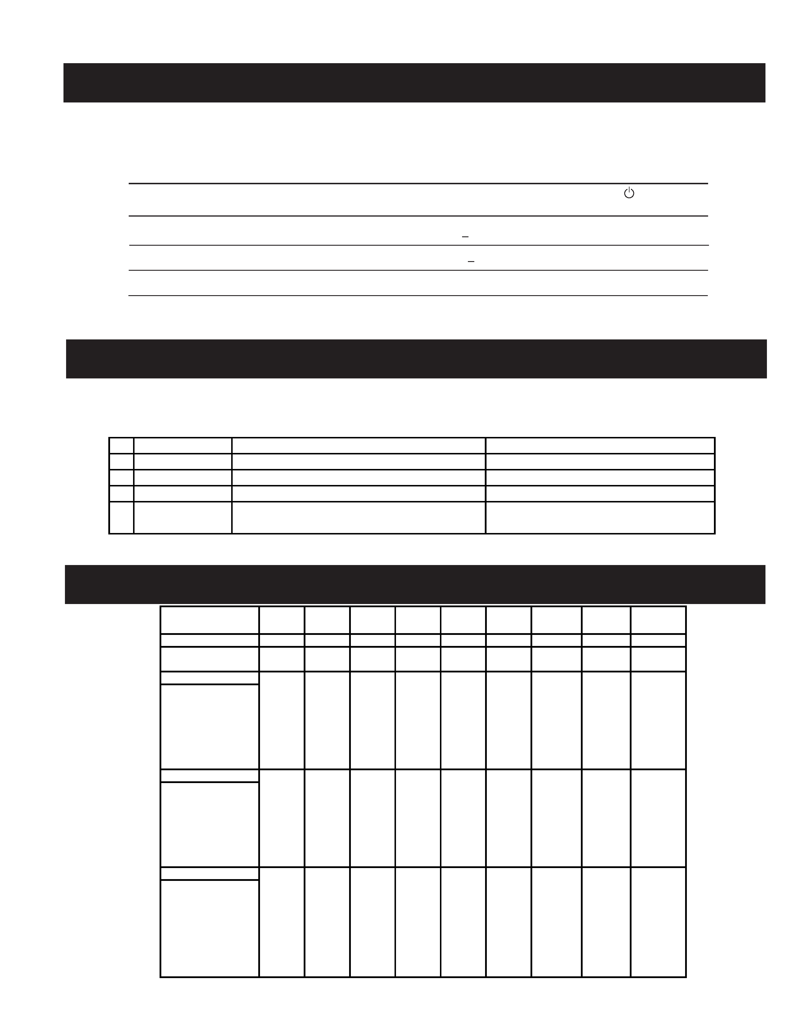
TIMING SPECIFICATION
SELF DIAGNOSIS FUNCTION
When a failure occurs, the STANDBY/TIMER lamp will ßash a set number of times to indicate the possible cause of the problem. If there is more than
one error, the lamp will identify the Þrst of the problem areas.
Power consumption
Screen
Horizontal
Vertical
Power
Recovery time
indicator
mode
(video)
sync signal sync signal consumption
1
Normal operation
active
yes
yes
< 100 W
--
Green
2
Active-off (3rd mode)
blank
no*
no*
< 3 W
Approx. 10 sec.
Orange
3
Power-off
--
--
--
0 W (approx)
--
Off
* In this mode, the signal will appear in one of three ways: The Horizontal Sync Signal alone off, the Vertical Sync Signal
alone off, or both signals off.
PRIME
MODE
MODE
1
2
3
4
5
6
7
8
9
RESOLUTION 640 X 480 640 X 480 720 X 400 800 X 600 800 X 600 832 X 624 1024 X 768 1024 X 768 1280 X 1024
CLOCK
25.175
36
28.322
49.5
56.25
57.283
78.75
94.5
108
HORIZONTAL
H. FREQ
31.469
43.269
31.469
46.875
53.674
49.725
60.023
68.677
63.981
H. TOTAL
31.778
23.111
31.777
21.333
18.631
20.111
16.660
14.561
15.630
H. BLK
6.356
5.333
6.355
5.172
4.409
5.586
3.657
3.725
3.778
H. FP
0.636
1.556
0.636
0.323
0.569
0.559
0.203
0.508
0.444
H. SYNC
3.813
1.556
3.813
1.616
1.138
1.117
1.219
1.016
1.037
H. BP
1.907
2.222
1.907
3.232
2.702
3.910
2.235
2.201
2.296
H. ACTIV25.422
17.778
25.422
16.162
14.222
14.524
13.003
10.836
11.852
VERTICAL
V. FREQ
59.940
85.008
70.087
75.000
85.061
74.550
75.029
84.997
60.020
V. TOTAL
16.683
11.764
14.268
13.333
11.756
13.414
13.328
11.765
16.661
V. BLK
1.430
0.670
1.557
0.533
0.578
0.865
0.533
0.582
0.656
V. FP
0.318
0.023
0.381
0.021
0.019
0.020
0.017
0.015
0.016
V. SYNC
0.064
0.069
0.064
0.064
0.056
0.060
0.050
0.044
0.047
V. BP
1.049
0.578
1.112
0.448
0.503
0.784
0.466
0.524
0.594
V. ACTIV
15.253
11.093
12.711
12.800
11.179
12.549
12.795
11.183
16.005
SYNC
INT (G)
NO
NO
NO
NO
NO
NO
NO
NO
NO
EXT (H/V) / POLARITY
YES
YES
YES
YES
YES
YES
YES
YES
YES
EXT (CS) / POLARITY
NO
NO
NO
NO
NO
NO
NO
NO
NO
SERRATION
NO
NO
NO
NO
NO
NO
NO
NO
NO
SYNC LEVEL
TTL
TTL
TTL
TTL
TTL
TTL
TTL
TTL
TTL
VIDEO
VIDEO LEVEL
0.7
0.7
0.7
0.7
0.7
0.7
0.7
0.7
0.7
SET UP
000000
0
0
0
6WDWXV
$UHDRI)DLOXUH
/(',QGLFDWLRQ
)DLOXUH
+9RU%
$PEHUVHFRQG
2IIVHFRQG
)DLOXUH
+6WRS96WRSRU6&RQQHFWLRQ)DLOXUH
$PEHUVHFRQG
2IIVHFRQG
)DLOXUH
$%/
$PEHUVHFRQG
2IIVHFRQG
$JLQJ6HOI7HVW$PEHUVHFRQG
2IIVHFRQG
*UHHQVHFRQG
2IIVHFRQG

-- 5 --
CPD-E240
WARNINGS AND CAUTIONS
CAUTION
Short circuit the anode of the picture tube and the anode cap to the metal chassis, CRT shield, or carbon painted on the CRT, after
removing the anode.
WARNING!!
An isolation transformer should be used during any service to avoid possible shock hazard, because of live chassis. The chassis of this
receiver is directly connected to the AC power line.
! SAFETY-RELATED COMPONENT WARNING!!
Components identiÞed by shading and ! mark on the schematic diagrams, exploded views, and in the parts list are critical for safe
operation. Replace these components with sony parts whose part numbers appear as shown in this manual or in supplements published
by sony. Circuit adjustments that are critical for safe operation are identiÞed in this manual. Follow these procedures whenever critical
components are replaced or improper operation is suspected.
ATTENTION!!
Apres avoir deconnecte le cap de l'anode, court-circuiter l'anode du tube cathodique et celui de l'anode du cap au chassis metallique de
l'appareil, ou la couche de carbone peinte sur le tube cathodique ou au blindage du tube cathodique.
AÞn d'eviter tout risque d'electrocution provenant d'un chássis sous tension, un transformateur d'isolement doit etre utilisé lors de tout
dépannage. Le chássis de ce récepteur est directement raccordé à l'alimentation du secteur.
! ATTENTION AUX COMPOSANTS RELATIFS A LA SECURITE!!
Les composants identiÞes par une trame et par une marque ! sur les schemas de principe, les vues explosees et les listes de pieces
sont d'une importance critique pour la securite du fonctionnement. Ne les remplacer que par des composants sony dont le numero
de piece est indique dans le present manuel ou dans des supplements publies par sony. Les reglages de circuit dont l'importance est
critique pour la securite du fonctionnement sont identiÞes dans le present manuel. Suivre ces procedures lors de chaque remplacement
de composants critiques, ou lorsqu'un mauvais fonctionnement suspecte.