
SPECIFICATIONS
F99
Picture tube
Video image area
Resolution
Standard image
area
Input signal
Video
Sync
0.24 mm (center) -0.25mm (edge)
aperture grill pitch
19 inches measured diagonally
90-degree deflection
(18" maximum viewing image)
Approx. 364.8 X 273.6 mm (w/h)
(143/8 x 107/8 inches)
Horizontal: Max. 1600 dots
Vertical: Max. 1200 lines
Approx. 352 x 264 mm (w/h)
(137/8 x 101/2 inches)
Analog RGB (75 ohms typical)
0.7 Vp-p, Positive
Separate Horizontal and Vertical
TTL level, Positive or Negative
Video Composite (Sync on Green)
0.3 Vp-p
Power Consumption
Maximum
Nominal
Deflection frequency
AC input voltage/current
Dimensions
Mass
CHASSIS
140 W, 478 BTU/h
100 W, 341BTU/h
Horizontal: 30 to 107 KHz (automatic)
Vertical: 48 to120 Hz (automatic)
100 to 120 V, 50/60 Hz,
1.8A (RMS) at 100VAC
220 to 240V, 50/60Hz,
1.0A (RMS) at 240 VAC
449 x 463 x 463 mm (w/h/d)
(172/3 x 181/5 x 181/5 inches)
Approx. 26.0 kg (57 lb 5 oz)
SERVICE MANUAL
Design and specifications are subject to change without notice.
CPD-4401
TRINITRON® COLOR MONITOR
CPD-4401
US Model
Canadian Model
AEP Model
Chassis No. SCC-L30N-A
866 Front.p65
10/15/1999, 10:41 AM
1
-- 2 --
CPD-4401
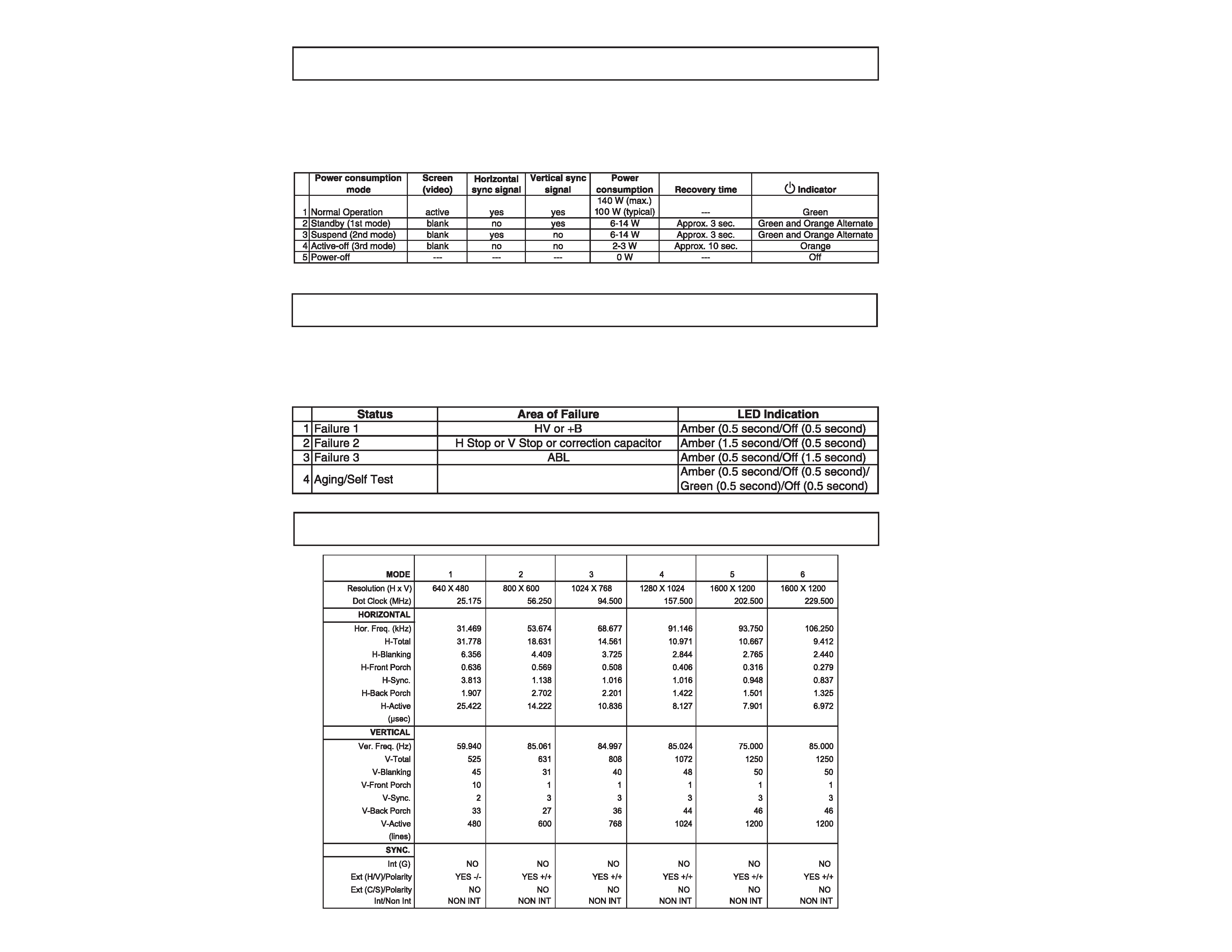
If you have VESA's DPMS compliance display card or software installed in your PC, the monitor can automatically reduce
its power consumption when not in use. If input from keyboard, mouse, or other input devices is detected, the monitor
will automatically "wake up." The following table shows the power consumption and signaling of this automatic power
saving feature.
When a failure occurs, the STANDBY/TIMER lamp will flash a set number of times to indicate the possible cause of the
problem. If there is more than one error, the lamp will identify the first of the problem areas.
SELF DIAGNOSTIC FUNCTION
POWER MANAGEMENT MODES
TIMING SPECIFICATIONS
-- 3 --
CPD-4401
1.5 k
0.15 µF
AC
Voltmeter
(0.75 V)
To Exposed Metal
Parts on Set
Earth Ground
SAFETY CHECK-OUT
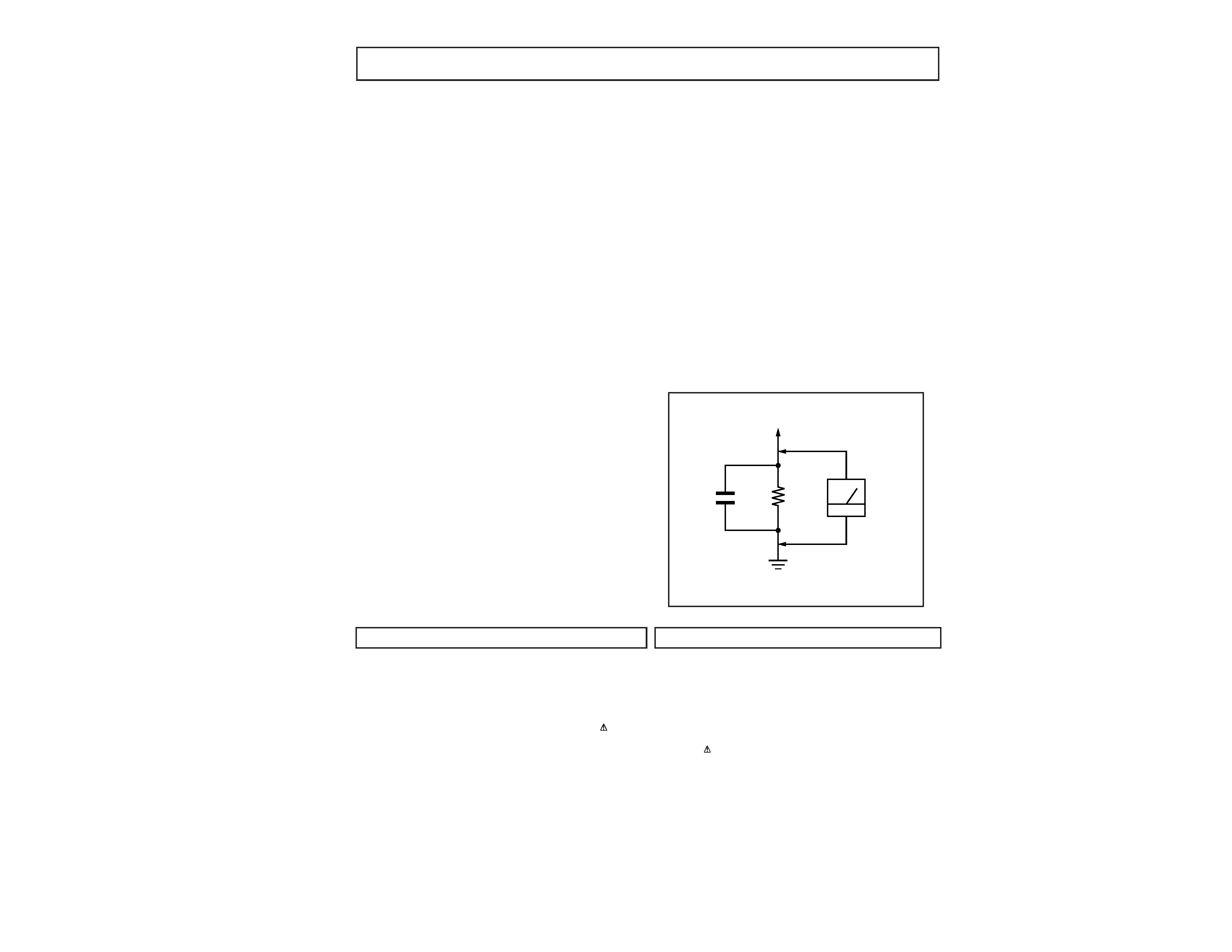
LEAKAGE TEST
The AC leakage from any exposed metal part to earth ground
and from all exposed metal parts to any exposed metal part
having a return to chassis, must not exceed 0.5 mA (500
microampere). Leakage current can be measured by any one
of three methods.
WARNING!!
NEVER TURN ON THE POWER IN A CONDITION IN WHICH THE
DEGAUSS COIL HAS BEEN REMOVED.
SAFETY-RELATED COMPONENT WARNING!!
COMPONENTS IDENTIFIED BY SHADING AND MARK
ON THE
SCHEMATIC DIAGRAMS, EXPLODED VIEWS AND IN THE PARTS
LIST ARE CRITICAL FOR SAFE OPERATION. REPLACE THESE
COMPONENTS WITH SONYPARTS WHOSE PART NUMBERSAPPEAR
AS SHOWN IN THIS MANUAL OR IN SUPPLEMENTS PUBLISHED BY
SONY. CIRCUIT ADJUSTMENTS THAT ARE CRITICAL FOR SAFE
OPERATION ARE IDENTIFIED IN THIS MANUAL. FOLLOW THESE
PROCEDURES WHENEVER CRITICALCOMPONENTSARE REPLACED
OR IMPROPER OPERATION IS SUSPECTED.
After correcting the original service problem, perform
the following safety checks before releasing the set to
the customer:
1. Check the area of your repair for unsoldered or poorly-
soldered connections. Check the entire board surface
for solder splashes and bridges.
2. Check the interboard wiring to ensure that no wires
are "pinched" or contact high-wattage resistors.
3. Check that all control knobs, shields, covers, ground
straps, and mounting hardware have been replaced.
Be absolutely certain that you have replaced all the
insulators.
4. Look for unauthorized replacement parts, particularly
transistors, that were installed during a previous
repair.
Point them out to the customer and
recommend their replacement.
5. Look for parts which, though functioning, show
obvious signs of deterioration. Point them out to the
customer and recommend their replacement.
6. Check the line cords for cracks and abrasion.
Recommend the replacement of any such line cord
to the customer.
7. Check the B+ and HV to see if they are specified
values. Make sure your instruments are accurate; be
suspicious of your HV meter if sets always have low
HV.
8. Check the antenna terminals, metal trim, "metallized"
knobs, screws, and all other exposed metal parts for
AC Leakage. Check leakage as follows.
1. A commercial leakage tester, such as the Simpson 229
or RCA WT-540A. Follow the manufacturers' instructions
to use these instructions.
2. A battery-operated AC milliammeter. The Data Precision
245 digital multimeter is suitable for this job.
3. Measuring the voltage drop across a resistor by means
of a VOM or battery-operated AC voltmeter. The "limit"
indication is 0.75 V, so analog meters must have an
accurate low voltage scale. The Simpson's 250 and
Sanwa SH-63TRD are examples of passive VOMs that
are suitable. N early all battery operated digital
multimeters that have a 2V AC range are suitable. (See
Figure A)
Figure A
AVERTISSEMENT!!
NE JAMAIS METTRE SOUS TENSION QUAND LA BOBINE DE
DEMAGNETISATION EST ENLEVEE.
ATTENTION AUX COMPOSANTS RELATIFS A LA SECURITE!!
LES COMPOSANTS IDENTIFIES PAR UNE TRAME ET PAR UNE
MARQUE
SUR LES SCHEMAS DE PRINCIPE, LES VUES
EXPLOSEES ET LES LISTES DE PIECES SONT D'UNE IMPORTANCE
CRITIQUE POUR LA SECURITE DU FONCTIONNEMENT. NE LES
REMPLACER QUE PAR DES COMPOSANTS SONY DONT LE
NUMERO DE PIECE EST INDIQUE DANS LE PRESENT MANUEL OU
DANS DES SUPPLEMENTS PUBLIES PAR SONY. LES REGLAGES
DE CIRCUIT DONT L'IMPORTANCE EST CRITIQUE POUR LA
SECURITE DU FONCTIONNEMENT SONT IDENTIFIES DANS LE
PRESENT MANUEL. SUIVRE CES PROCEDURES LORS DE CHAQUE
REMPLACEMENT DE COMPOSANTS CRITIQUES, OU LORSQU'UN
MAUVAIS FONTIONNEMENT SUSPECTE.

-- 4 --
CPD-4401
Section
Title
Page
SAFETY CHECK-OUT ............................................................................. 3
1.
GENERAL ........................................................................................ 5
2.
DISASSEMBLY
2-1. Cabinet/Shield Removal ............................................. 10
2-2. Service Position ........................................................... 10
2-3. D, A, H and N Board Removal ..................................... 10
2-4. Picture Tube Removal ................................................. 11
3.
SAFETY RELATED ADJUSTMENT ................................................ 12
4.
ADJUSTMENTS ............................................................................ 13
5.
DIAGRAMS
5-1. Block Diagram ............................................................. 15
5-2. Circuit Boards Location ............................................... 18
5-3. Schematic Diagrams and Printed Wiring Boards ...... 18
1. D Board - Schematic Diagram .............................. 19
2. H Board - Schematic Diagram .............................. 25
3. N Board - Schematic Diagram .............................. 26
4. A Board - Schematic Diagram ............................... 27
5-4. Semiconductors .......................................................... 30
6.
EXPLODED VIEWS
6-1-1. Chassis (US/Canada Model) ................................... 32
6-1-2. Chassis (AEP Model) ................................................ 33
6-2. Packing Materials ......................................................... 34
7.
ELECTRICAL PARTS LIST ............................................................ 35
TABLE OF CONTENTS
--
5
--
CPD-4401
SECTION 1
GENERAL
The instructions given are partial abstracts from
the Operating Instruction Manual. The page num-
bers shown reflect those of the Operating Instruc-
tion Manual
3
US
Precautions
Installation
Do not install the monitor in the following places:
· on surfaces (rugs, blankets, etc.) or near materials (curtains,
draperies) that may block the ventilation holes
· near heat sources such as radiators or air ducts, or in a place
subject to direct sunlight
· in a place subject to severe temperature changes
· in a place subject to mechanical vibration or shock
· on an unstable surface
· near equipment which generates magnetism, such as a
transformer or high voltage power lines
· near or on an electrically charged metal surface
Maintenance
· Clean the screen with a soft cloth. If you use a glass cleaning
liquid, do not use any type of cleaner containing an anti-static
solution or similar additive as this may scratch the screen's
coating.
· Do not rub, touch, or tap the surface of the screen with sharp or
abrasive items such as a ball point pen or screwdriver. This type
of contact may result in a scratched picture tube.
· Clean the cabinet, panel and controls with a soft cloth lightly
moistened with a mild detergent solution. Do not use any type of
abrasive pad, scouring powder or solvent, such as alcohol or
benzene.
Transportation
When you transport this monitor for repair or shipment, use the
original carton and packing materials.
Warning on Power Connection
· Use the supplied power cord. If you use a different power cord,
be sure that it is compatible with your local power supply.
For the customers in the US
If you do not use the appropriate cord, this monitor will not
conform to mandatory FCC Standards.
· Before disconnecting the power cord, wait at least 30 seconds
after turning off the power to allow the static electricity on the
screen's surface to discharge.
· After the power is turned on, the screen is demagnetized
(degaussed) for about 3 seconds. This generates a strong
magnetic field around the screen, which may affect data stored on
magnetic tapes and disks placed near the monitor. Be sure to keep
magnetic recording equipment, tapes and disks away from the
monitor.
The equipment should be installed near an easily accessible
outlet.
Example of plug types
for 100 to 120 V AC
for 200 to 240 V AC
4
Setup
Connect the monitor to your computer system.
This monitor will sync to platforms running at horizontal
frequencies between 30 and 107 kHz.
Step 1 Make sure the computer system is switched off and attach
the video signal cable to the video output of the computer.
Step 2 Make sure the computer is switched off and attach the
power cord to the monitor. Then, attach the other end of
the power cord to a power outlet.
Step 3 Switch on the monitor and computer.
Step 4 Adjust the user controls according to your personal
preference.
Installation is complete.
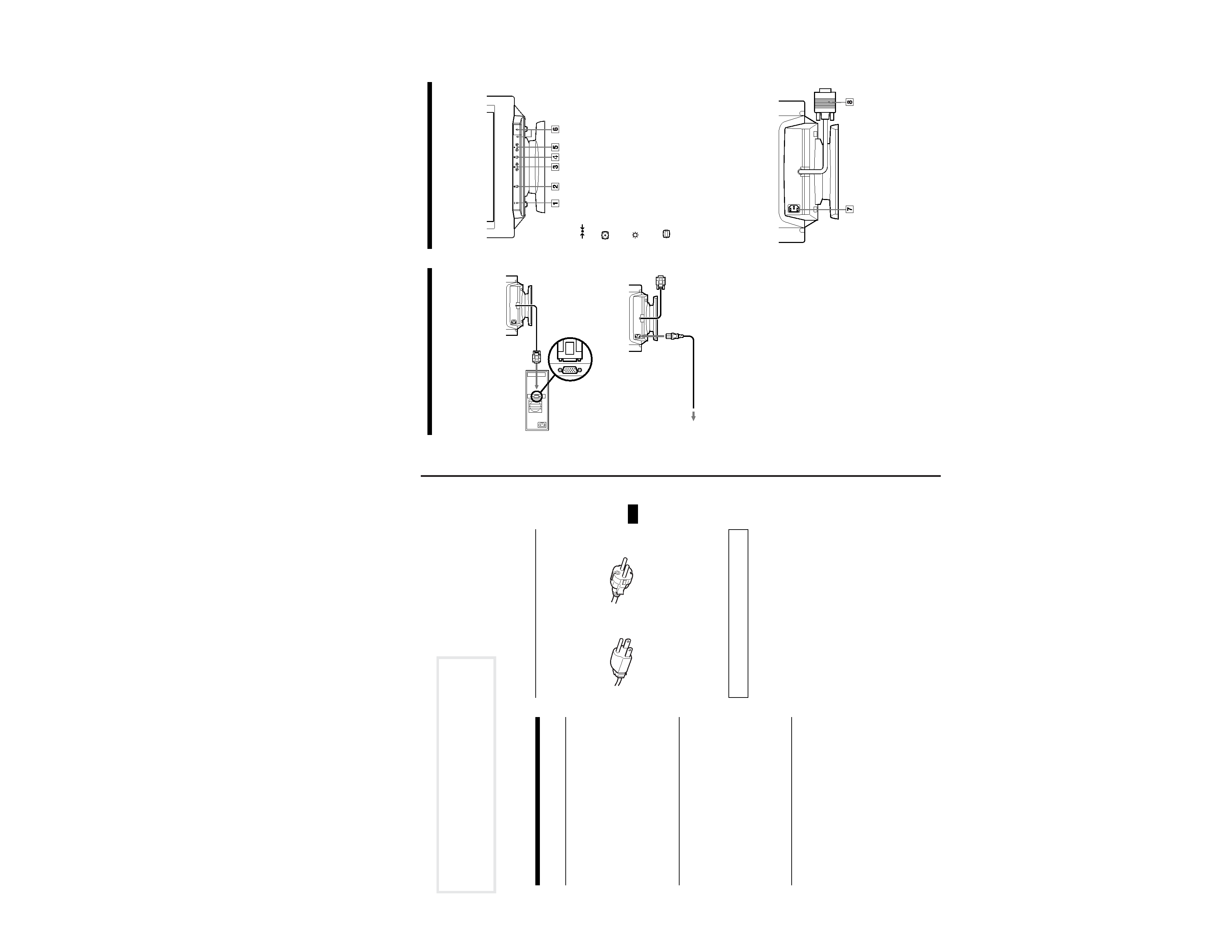
Identifying parts and
controls
1
(RESET) button (pages 6, 9)
This button resets the adjustments to the factory settings.
2
(AUTOSIZING AND CENTERING) button (page 5)
This button automatically fills the screen and adjusts vertical
and horizontal centering.
3
(BRIGHTNESS) (
v/V) buttons (page 5)
These buttons adjust the picture brightness and function as the
(
v/V) buttons when adjusting other items.
4
(MENU) button (page 6)
This button displays the MENU OSD.
5 6 (CONTRAST) (B/b) buttons (page 5)
These buttons adjust the contrast and function as the (
B/b)
buttons when adjusting other items.
6 1 (POWER) switch and indicator
This button turns the monitor on and off.
The indicator lights up green when the monitor is on, and lights
up green and orange when the monitor is in Power Saving
mode.
7 AC IN connector
This connector provides AC power to the monitor.
8 Video input connector (HD15) (page 5)
This connector inputs RGB video signals and SYNC signals.
Computer
to the video output
to a power outlet
Power cord
Front
Rear