SPECIFICATIONS
D99 CHASSIS
SERVICEMANUAL
CPD-2403
CPD-2403
AEP Model
Chassis No. SCC-L29R-A
TRINITRON
®
COLOR MONITOR
Picture tube
Video image area
Resolution
Standard image
area
Input signal
Video
Sync
0.24-0.25 mm aperture grill pitch
17 inches measured diagonally
90-degree deflection
(16" maximum viewing image)
Approx. 327 X 243 mm (w/h)
(127/8 x 95/8 inches)
Horizontal: Max. 1600 dots
Vertical: Max. 1200 lines
Approx. 312 x 234 mm (w/h)
(121/4 x 91/4 inches)
Analog RGB (75 ohms typical)
0.7 Vp-p, ±5%, Positive
Separate HD/VD,
TTL Polarity Free
External Composite,
TTL Polarity Free (2K ohms impedance)
Power Consumption
Deflection frequency
AC input voltage /
current
Dimensions
Mass
Maximum 130W
Minimum 95W
Horizontal: 30 to 94 KHz
Vertical: 48 to 120 Hz
100 to 120 V, 50/60 Hz, 1.7A
220 to 240V, 50/60Hz, 0.9A
404 x 414 x 420mm (w/h/d)
(1515/16 x 163/8 x 161/2 inches)
Approx. 18.8 kg (41 lb 7 oz.)
Design and specifications are subject to change without notice.
-- 2 --
CPD-2403
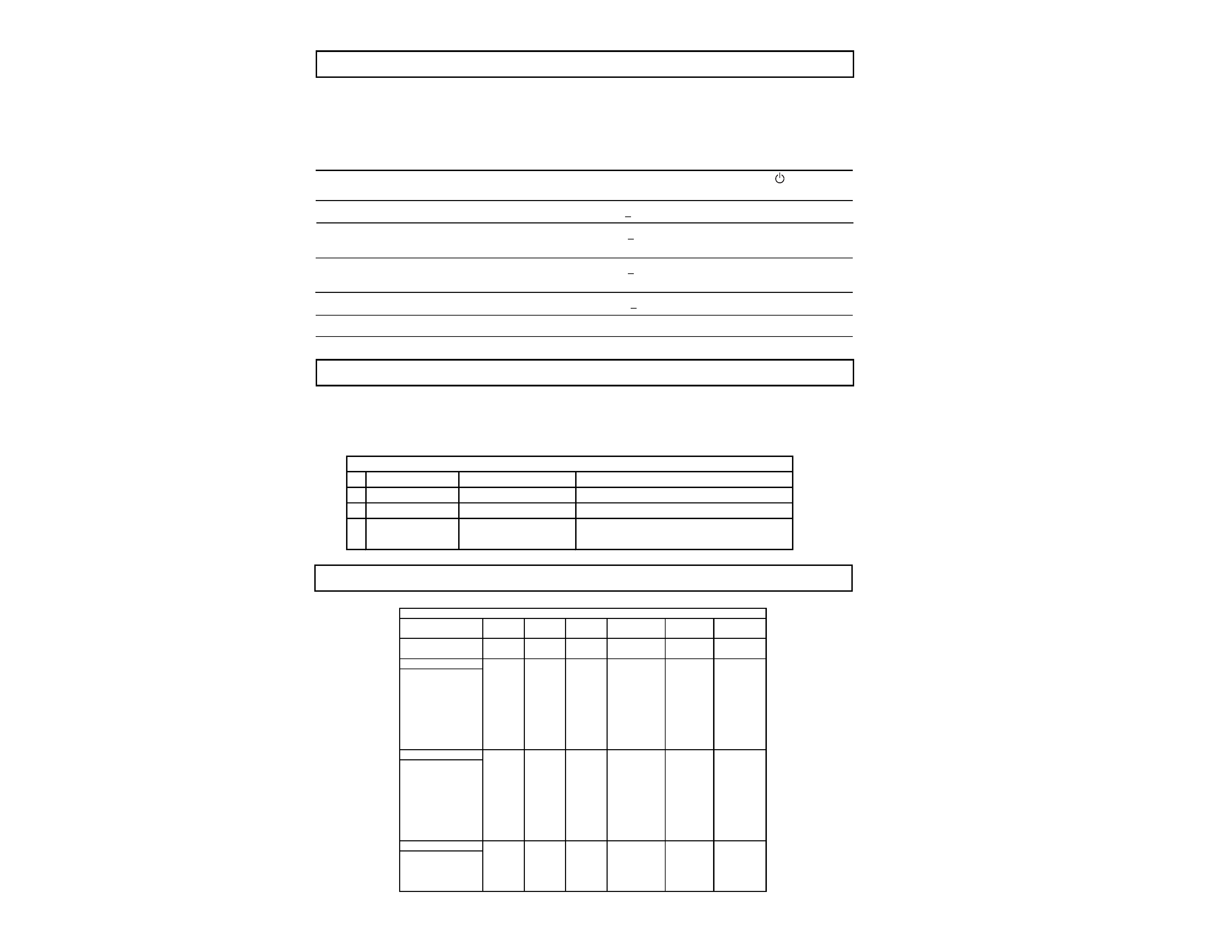
POWER MANAGEMENT
The power saving mode complies with the VESA Display Power Management Signaling standard. Each
state of power management shall be activated by the host computer terminating the appropriate sync
signals. Blanking the video must precede termination of the sync signals. The elapsed time counter
shall also be controlled by the host computer. Reactivation of the monitor shall be accomplished from
the host computer by re-establishing the normal sync signal.
When a failure occurs, the STANDBY/TIMER lamp will flash a set number of times to indicate the
possible cause of the problem. If there is more than one error, the lamp will identify the first of the
problem areas.
Power consumption
Screen
Horizontal
Vertical
Power
Recovery time
indicator
mode
(video)
sync signal
sync signal consumption
1
Normal operation
active
yes
yes
< 130 W
--
Green
2
Standby (1st mode)
blank
no
yes
< 15 W
Approx. 3 sec.
Green and Orange
Alternate
3
Suspend (2nd mode)
blank
yes
no
< 15 W
Approx. 3 sec.
Green and Orange
Alternate
4
Active-off (3rd mode)
blank
no
no
< 3 W
Approx. 10 sec.
Orange
5
Power-off
--
--
--
0 W
--
Off
Status
Area of Failure
LED Indication
1 Failure 1
HV or +B
Amber (0.5 second)/Off (0.5 second)
2 Failure 2
H Stop or V Stop
Amber (1.5 second)/Off (0.5 second)
3 Failure 3
ABL
Amber (0.5 second)/Off (1.5 second)
4 Aging/Self Test
Amber (0.5 second)/Off (0.5 second)/
Green (0.5 second)/Off (0.5 second)
TIMING SPECIFICATION
SELF DIAGNOSIS FUNCTION
TIMING SPECIFICATION
Primary Mode
MODE
123
4
5
6
Resolution (H x V) 640 x 480 720 x 400 800 x 600
1024 x 768 1280 x 1024 1600 x 1200
Dot Clock (MHz)
25.175
28.322
56.250
94.500
135.000
202.500
HORIZONTAL
Hor. Freq. (kHz)
31.469
31.469
53.674
68.677
79.976
93.750
H-Total
31.778
31.777
18.631
14.561
12.504
10.667
H-Blanking
6.356
6.355
4.409
3.725
3.022
2.765
H-Front Porch
0.636
0.636
0.569
0.508
0.119
0.316
H-Sync.
3.813
3.813
1.138
1.016
1.067
0.948
H-Back Porch
1.907
1.907
2.702
2.201
1.837
1.501
H-Active
25.422
25.422
14.222
10.836
9.481
7.901
(µsec.)
VERTICAL
Ver. Freq. (Hz)
59.940
70.087
85.061
84.997
75.025
75.000
V-Total
525
449
631
808
1066
1250
V-Blanking4549
31
40
42
50
V-Front Porch1012
1
1
1
1
V-Sync.
2
2
3
3
3
3
V-Back Porch
33
35
27
36
38
46
V-Active
480
400
600
768
1024
1200
(lines)
SYNC.
Int (G)
NoNoNo
No
No
No
Ext (H/V)/Polarity
Yes -/-
Yes -/+
Yes +/+
Yes +/+
Yes +/+
Yes +/+
Ext (CS)/Polarity
No
No
No
No
No
No
Int/Non Int
Non Int
Non Int
Non Int
Non Int
Non Int
Non Int
-- 3 --
CPD-2403
TABLE OF CONTENTS
Section
Title
Page
Safety Check Out Instructions .............................................................. 4
1. GENERAL .................................................................................. 5
2. DISASSEMBLY
2-1. Cabinet Removal ........................................................... 9
2-2. Service Position ............................................................. 9
2-3. A and D Board Removal ............................................... 9
2-4. Picture Tube Removal ................................................. 10
3. SAFETY RELATED ADJUSTMENTS ........................... 11
4. ADJUSTMENTS .................................................................... 12
5. DIAGRAMS
5-1. Block Diagram .............................................................. 15
5-2. Circuit Boards Location ................................................ 18
5-3. Schematic Diagrams and Printed Wiring Boards ......... 18
1. D Board - Schematic Diagram ............................... 19
2. A Board - Schematic Diagram ............................... 26
5-4. Semiconductors ........................................................... 29
6. EXPLODED VIEWS
6-1. Chassis ........................................................................ 31
6-2. Packing Materials ........................................................ 32
7. ELECTRICAL PARTS LIST .............................................. 33
-- 4 --
CPD-2403
1.5 k
0.15 µF
AC
Voltmeter
(0.75 V)
To Exposed Metal
Parts on Set
Earth Ground
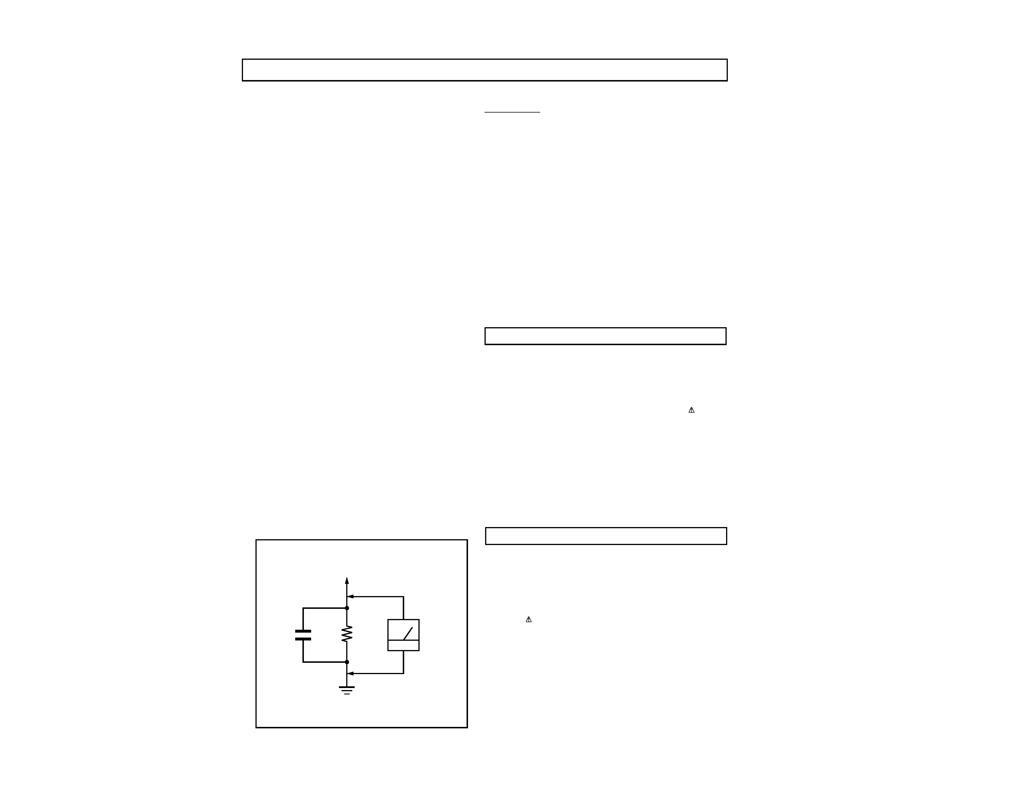
SAFETY CHECK-OUT
After correcting the original service problem, perform the
following safety checks before releasing the set to the
customer:
Leakage Test
The AC leakage from any exposed metal part to earth ground
and from all exposed metal parts to any exposed metal part
having a return to chassis, must not exceed 0.5 mA (500
microampere). Leakage current can be measured by any one of
three methods.
WARNING!!
NEVER TURN ON THE POWER IN A CONDITION IN WHICH THE
DEGAUSS COIL HAS BEEN REMOVED.
SAFETY-RELATED COMPONENT WARNING!!
COMPONENTS IDENTIFIED BY SHADING AND MARK
ON THE
SCHEMATIC DIAGRAMS, EXPLODED VIEWS AND IN THE PARTS
LIST ARE CRITICAL FOR SAFE OPERATION. REPLACE THESE
COMPONENTS WITH SONY PARTS WHOSE PART NUMBERS
APPEAR AS SHOWN IN THIS MANUAL OR IN SUPPLEMENTS
PUBLISHED BY SONY. CIRCUIT ADJUSTMENTS THAT ARE
CRITICAL FOR SAFE OPERATION ARE IDENTIFIED IN THIS
MANUAL. FOLLOWTHESE PROCEDURES WHENEVER CRITICAL
COMPONENTS ARE REPLACED OR IMPROPER OPERATION IS
SUSPECTED.
AVERTISSEMENT!!
NE JAMAIS METTRE SOUS TENSION QUAND LA BOBINE DE
DEMAGNETISATION EST ENLEVEE.
ATTENTION AUX COMPOSANTS RELATIFS A LA SECURITE!!
LES COMPOSANTS IDENTIFIES PAR UNE TRAME ET PAR UNE
MARQUE
SUR LES SCHEMAS DE PRINCIPE, LES VUES
EXPLOSEES ET LES LISTES DE PIECES SONT D'UNE
IMPORTANCE
CRITIQUE
POUR
LA
SECURITE
DU
FONCTIONNEMENT. NE LES REMPLACER QUE PAR DES
COMPOSANTS SONY DONT LE NUMERO DE PIECE EST
INDIQUE DANS LE PRESENT MANUEL OU DANS DES
SUPPLEMENTS PUBLIES PAR SONY. LES REGLAGES DE
CIRCUIT DONT L'IMPORTANCE EST CRITIQUE POUR LA
SECURITE DU FONCTIONNEMENT SONT IDENTIFIES DANS LE
PRESENT MANUEL. SUIVRE CES PROCEDURES LORS DE
CHAQUE REMPLACEMENT DE COMPOSANTS CRITIQUES, OU
LORSQU'UN MAUVAIS FONTIONNEMENT SUSPECTE.
1. Check the area of your repair for unsoldered or poorly-
soldered connections. Check the entire board surface
for solder splashes and bridges.
2. Check the interboard wiring to ensure that no wires are
"pinched" or contact high-wattage resistors.
3. Check that all control knobs, shields, covers, ground
straps, and mounting hardware have been replaced. Be
absolutely certain that you have replaced all the
insulators.
4. Look for unauthorized replacement parts, particularly
transistors, that were installed during a previous repair.
Point them out to the customer and recommend their
replacement.
5. Look for parts which, though functioning, show obvious
signs of deterioration. Point them out to the customer
and recommend their replacement.
6. Check the line cords for cracks and abrasion.
Recommend the replacement of any such line cord to
the customer.
7. Check the B+ and HV to see if they are specified values.
Make sure your instruments are accurate; be suspicious
of your HV meter if sets always have low HV.
8. Check the antenna terminals, metal trim, "metallized"
knobs, screws, and all other exposed metal parts for
AC Leakage. Check leakage as described below.
1. A commercial leakage tester, such as the Simpson 229 or
RCA WT-540A. Follow the manufacturers' instructions to use
these instructions.
2. A battery-operated AC milliammeter.The Data Precision 245
digital multimeter is suitable for this job.
3. Measuring the voltage drop across a resistor by means of
a VOM or battery-operated AC voltmeter. The "limit"
indication is 0.75 V, so analog meters must have an accurate
low voltage scale. The Simpson's 250 and Sanwa SH-63Trd
are examples of passive VOMs that are suitable. Nearly
all battery operated digital multimeters that have a 2V AC
range are suitable. (See Figure A)
Figure A
--
5
--
CPD-2403
SECTION 1
GENERAL
The following are partial abstracts from the Operating Instruction
Manual. The page numbers shown reflect those of the Operating
Instruction Manual.
4
Getting Started
Setup
Connect the monitor to your computer system.
This monitor will sync to platforms running at horizontal frequencies between 30 and 85 kHz.
Step 1 Make sure the computer system is switched off and attach
the video signal cable to the video output of the computer.
Step 2 Make sure the computer is switched off and attach the
power cord to the monitor. Then, attach the other end of
the power cord to a power outlet.
Step 3 Switch on the monitor and computer.
Step 4 Adjust the user controls according to your personal
preference.
Installation is complete.
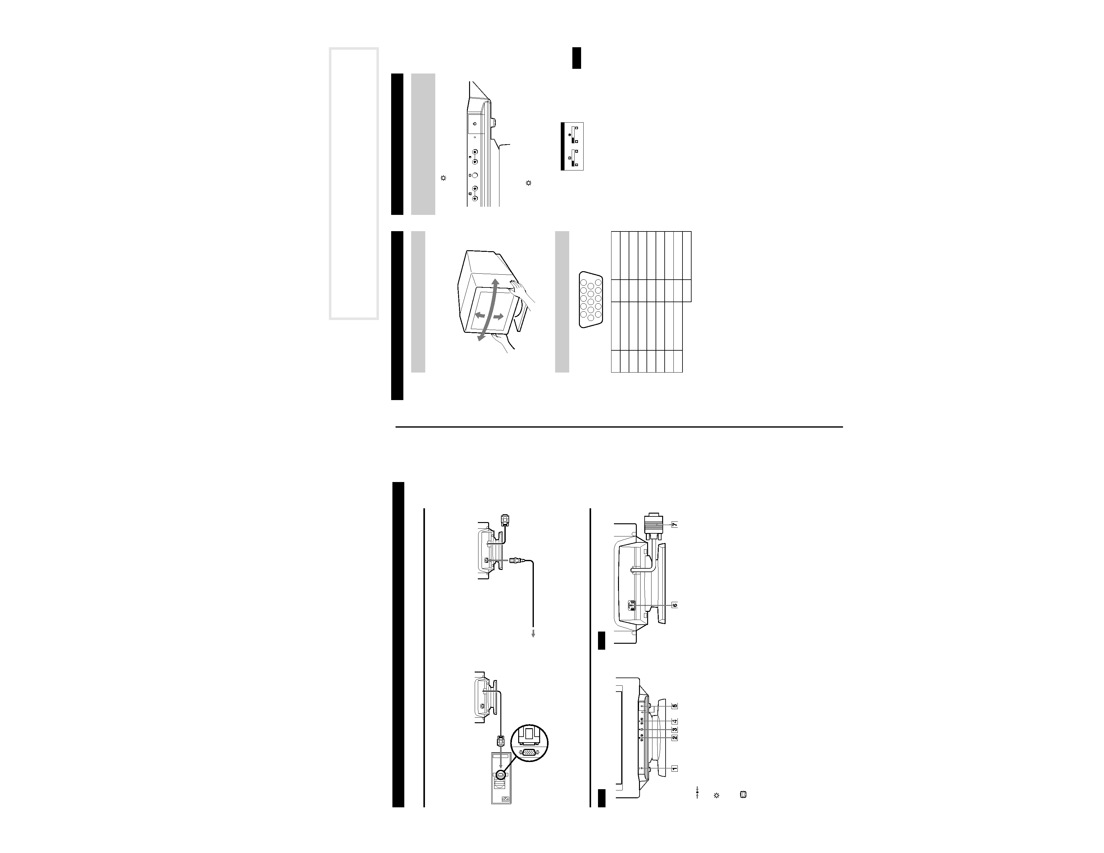
Parts and Controls
1
(RESET) button (pages 6, 9)
This button resets the adjustments to the factory settings.
2
(BRIGHTNESS) (
v/V) buttons (page 5)
These buttons adjust the picture brightness and function as the
(
v/V) buttons when adjusting other items.
3
(MENU) button (page 6)
This button displays the MENU OSD.
4 6 (CONTRAST) (B/b) buttons (page 5)
These buttons adjust the contrast and function as the (
B/b)
buttons when adjusting other items.
5 1 (POWER) switch and indicator
This button turns the monitor on and off.
The indicator lights up green when the monitor is on, and lights
up green and orange when the monitor is in Power Saving
mode.
6 AC IN connector
This connector provides AC power to the monitor.
7 Video input connector (HD15) (page 5)
This connector inputs RGB video signals and SYNC signals.
Computer
to the video output
to a power outlet
Power cord
Front
Rear
5
Getting Started
Customizing Your Monitor
US
This monitor can be adjusted within the angles shown below. To
turn the monitor vertically or horizontally, hold it at the bottom with
both hands.
1 Press the
(BRIGHTNESS)
v/V or 6 (CONTRAST)
B/b buttons.
The BRIGHTNESS/CONTRAST OSD appears.
2 To adjust the brightness.
Press the
(BRIGHTNESS)
v/V buttons.
To adjust the contrast.
Press the
6 (CONTRAST) B/b buttons.
Use of the Tilt/Swivel
Video Connector
Pin No. Signal
Pin No. Signal
1
Red video
8
Blue return
2
Green video
9
Not used (no pin)
3
Blue video
10
Ground
4
Ground
11
Ground
5
CPU host ground
12
SDA (serial data)
6
Red ground
13
Horizontal Sync
7
Green return
14
Vertical Sync
15
SCL (serial clock)
90°
5°
90°
15°
123 4
5
9
8
7
10
11 12 13 14 15
6
Adjusting the Picture Brightness
and Contrast
BRIGHTNESS/CONTRAST
26
26