CHASSIS
SERVICE MANUAL
SPECIFICATIONS
MICROFILM
V-3
US Model
Canadian Model
Chassis No. SCC-L21A-A
TRINITRON® MULTIMEDIA COMPUTER DISPLAY
CPD-201VS
Picture tube
0.25 mm aperture grille pitch,
17 inches measured diagonally
(16.0" viewable),
90-degree deflection,
AR coating
Viewable image size
Approx. 327
× 241 mm (w/h)
(12 7/8
× 9 1/2 inches)
16.0" viewing image
(measured diagonally)
Max. resolution
Horizontal: Max. 1280 dots
Vertical: Max. 1024 lines
VESA standards
640
× 480 at 85 Hz
800
× 600 at 85 Hz
1024
× 768 at 85 Hz
1280
× 1024 at 60 Hz
Deflection frequency
Horizontal: 30 to 70 kHz
Vertical: 50 to 120 Hz
Speaker
Left, right: 3.0 W
× 2
50 Hz 20 kHz
Microphones
Uni-directional, electret condenser
microphone
Microphones output
3.5 mm miniplug
Audio input
3.5 mm Stereo miniplug,
input impedance 47 k
,
input level 0.7 Vrms typical
Headphones output
Stereo minijack, 15 mW + 15 mW at
16
Subwoofer output
3.5 mm miniplug, volume variable
Controls
Front panel direct:
Audio volume/Contrast/Audio
mute/GPE (AUTO/off/mode 1/
mode 2)
OSD menu:
Brightness/Contrast/Picture size/
Picture zoom/Picture centering/
Sceen moiré/Color temperature
(5000K/6500K/9300K/11000K)/
Rotation/Pincushion/Pin balance/
Keystone/Key balance/Bass boost/
Manual Degauss/OSD position/
OSD language
AC input voltage/current
100 to 240 V, 50 60 Hz, 1.5 0.6 A
Power consumption
Max. 120 W
Dimensions
Approx. 415
× 451 × 423 mm
(w/h/d)
(16 3/8
× 17 5/8 × 16 3/4 inches)
Mass
Approx. 19.6 kg (43 lb 3 oz)
Design and specifications are subject to change without
notice.
CPD-201VS
2
DIAGNOSIS
Failure
Power LED
+B Failure
Blink Amber (On 0.5 sec, Off 0.5 sec)
H Stop or V Stop Failure
Blink Amber (On 1.5 sec, Off 0.5 sec)
(Included S-Cap Failure)
ABL Failure
Blink Amber (On 0.5 sec, Off 1.5 sec)
Aging/Self-Test
Blink Amber (On 0.5 sec, Off 0.5 sec) .... Blink Green (On 0.5 sec, Off 0.5 sec)
Out of Range
On Green (OSD Indication)
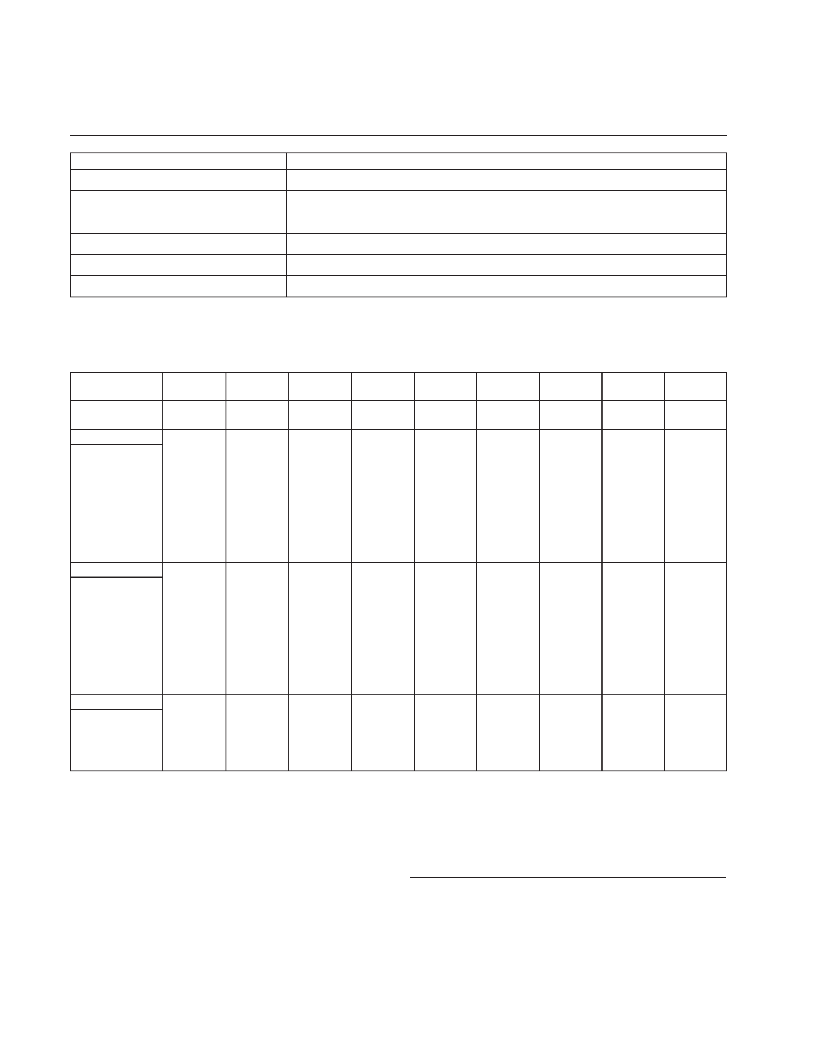
TIMING SPECIFICATION
Power Saving Function
This display meets the power saving guidelines set by the International
ENERGY STAR Program. It is capable of reduced power consumption
when used with a computer equipped with Display Power Management
Signaling (DPMS). By sensing the absence of the sync signal coming
from the computer, it will reduce the power consumption as follows:
CAUTION
The Power Saving function will automatically put the display into Deep Sleep mode if the
power switch is turned on without any video signal input. Once the horizontal and vertical
syncs are sensed, the display will automatically return to its Normal Operation mode.
Power
consumption
CPD-101VS: 110 W (max)
CPD-201VS: 120 W (max)
15 W (max)
8 W (max)
0 W
Normal
Operation
Sleep
Deep Sleep
Power-off
Recovery
time
--
Approx. 3 sec.
Approx. 10 sec.
--
U
Power
indicator
Green
Green ~
Orange
Orange
Off
Mode
1
2
3
4
PRIMARY MODE
PRIMARY
MODE AT PRODUCTION
MODE 1
MODE 2
MODE 3
MODE 4
MODE 5
MODE 6
MODE 7
MODE 8
MODE 9
RESOLUTION
640 X 480
800 X 600
800 X 600
1024 X 768
1024 X 768
1280 X 1024
640 X 400
640 X 480
1152 X 864
CLOCK
36.000 MHZ
40.000 MHZ
49.500 MHZ
78.750 MHZ
94.500 MHZ
108.500 MHZ
25.175 MHZ
25.175 MHZ
80.000 MHZ
-- HORIZONTAL --
H-FREQ
43.269 kHz
37.879 kHz
46.875 kHz
60.023 kHz
68.677 kHz
63.974 kHz
31.469 kHz
31.469 kHz
54.945 kHz
usec
usec
usec
usec
usec
usec
usec
usec
usec
H. TOTAL
23.111
26.4
21.333
16.66
14.561
15.631
31.778
31.778
18.2
H. BLK
5.333
6.4
5.172
3.657
3.725
3.834
6.356
6.356
3.8
H. FP
1.556
1
0.323
0.203
0.508
0.59
0.636
0.636
0.8
H. SYNC
1.556
3.2
1.616
1.219
1.016
1.18
3.813
3.813
1.4
H. BP
2.222
2.2
3.232
2.235
2.201
2.065
1.907
1.907
1.6
H. ACTIV
17.778
20
16.162
13.003
10.836
11.797
25.422
25.422
14.4
-- VERTICAL --
V. FREQ(HZ)
85.008 Hz
60.317 Hz
75.000 Hz
75.029 Hz
84.997 Hz
60.013 Hz
70.086 Hz
59.940 Hz
59.984 Hz
lines
lines
lines
lines
lines
lines
lines
lines
lines
V. TOTAL
509
628
625
800
808
1066
449
525
916
V. BLK
29
28
25
32
40
42
49
45
52
V. FP
111
111
12
10
6
V. SYNC
3
4
3
33322
5
V. BP
25
23
21
28
36
38
35
33
41
V. ACTIV
480
600
600
768
768
1024
400
480
864
-- SYNC --
INT(G)
NO
NO
NO
NO
NO
NO
NO
NO
NO
EXT(H/V)/POLARITY
YES -/-
YES +/+
YES +/+
NO +/+
YES +/+
YES +/+
YES -/+
YES -/-
YES +/+
EXT(CS)/POLARITY
NO
NO
NO
NO
NO
NO
NO
NO
NO
INT/NON INT
NON INT
NON INT
NON INT
NON INT
NON INT
NON INT
NON INT
NON INT
NON INT
98.4.27 VER.
CPD-201VS
3
LEAKAGE TEST
The AC leakage from any exposed metal part to earth ground
and from all exposed metal parts to any exposed metal part hav-
ing a return to chassis, must not exceed 0.5 mA (500
microampers).
Leakage current can be measured by any one of three methods.
1. A commercial leakage tester, such as the Simpson 229 or
RCA WT-540A. Follow the manufacturers' instructions to
use these instruments.
2. A battery-operated AC milliammeter. The Data Precision
245 digital multimeter is suitable for this job.
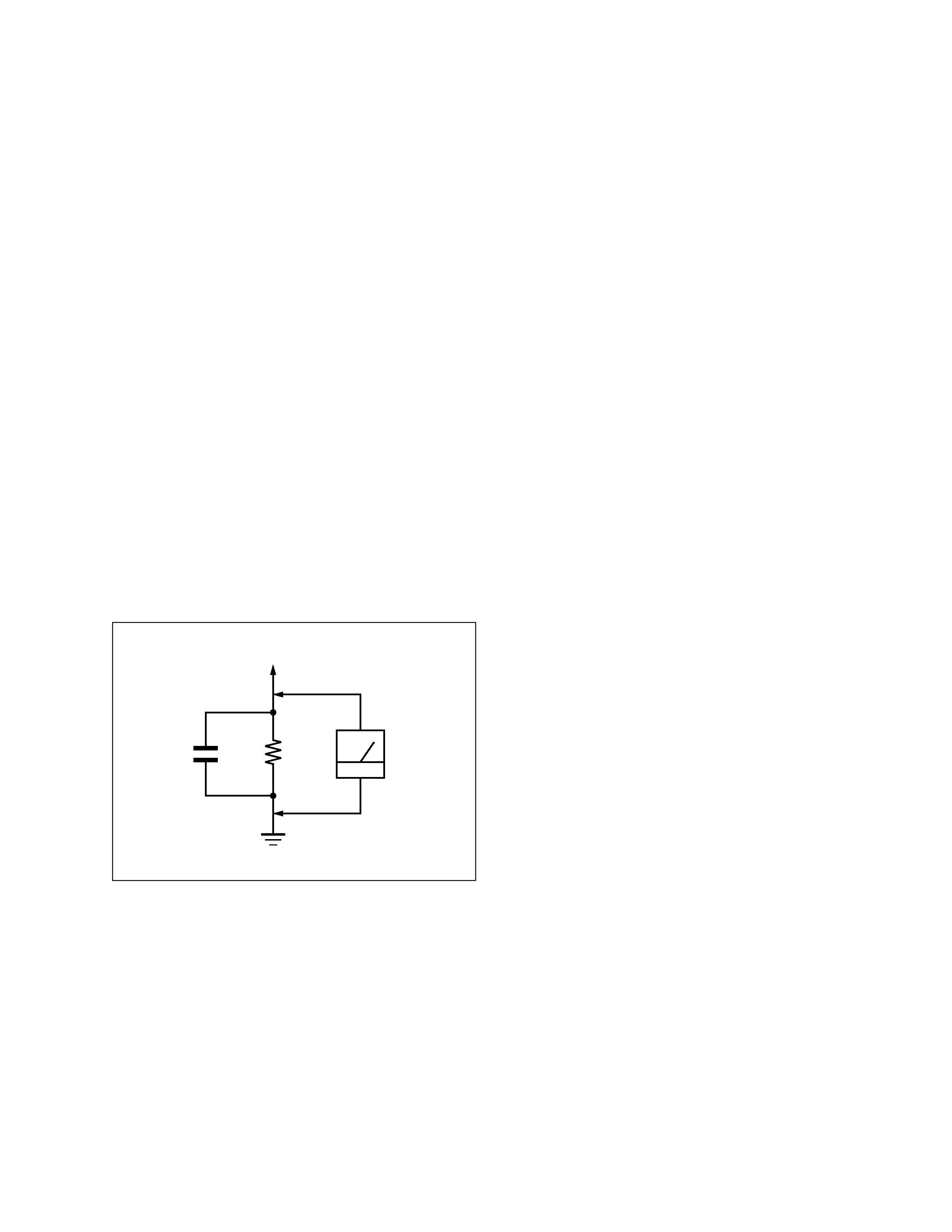
3. Measuring the voltage drop across a resistor by means of a
VOM or battery-operated AC voltmeter. The "limit" indica-
tion is 0.75 V, so analog meters must have an accurate low-
voltage scale. The Simpson 250 and Sanwa SH-63Trd are
examples of a passive VOMs that are suitable. Nearly all
battery operated digital multimeters that have a 2 V AC
range are suitable. (See Fig. A)
WARNING!!
NEVER TURN ON THE POWER IN A CONDITION IN
WHICH THE DEGAUSS COIL HAS BEEN REMOVED.
SAFETY-RELATED COMPONENT WARNING!!
COMPONENTS IDENTIFIED BY SHADING AND MARK
¡ ON THE SCHEMATIC DIAGRAMS, EXPLODED
VIEWS AND IN THE PARTS LIST ARE CRITICAL FOR
SAFE OPERATION. REPLACE THESE COMPONENTS
WITH SONY PARTS WHOSE PART NUMBERS AP-
PEAR AS SHOWN IN THIS MANUAL OR IN SUPPLE-
MENTS PUBLISHED BY SONY. CIRCUIT ADJUST-
MENTS THAT ARE CRITICAL FOR SAFE OPERATION
ARE IDENTIFIED IN THIS MANUAL. FOLLOW THESE
PROCEDURES WHENEVER CRITICAL COMPONENTS
ARE REPLACED OR IMPROPER OPERATION IS SUS-
PECTED.
AVERTISSEMENT!!
NE JAMAIS METTRE SOUS TENSION QUAND LA
BOBINE DE DEMAGNETISATION EST ENLEVÉE.
ATTENTION AUX COMPOSANTS RELATIFS À LA
SÉCURITÉ!!
LES COMPOSANTS IDENTIFIÉS PAR UNE TRAME ET
UNE MARQUE
¡ SONT CRITIQUES POUR LA SÉCURITÉ.
NE LES REMPLACER QUE PAR UNE PIÈCE PORTANT LE
NUMÉRO SPECIFIÉ. LES RÉGLAGES DE CIRCUIT DONT
L'IMPORTANCE EST CRITIQUE POUR LA SÉCURITÉ DU
FONCTIONNEMENT SONT IDENTIFIÉS DANS LE
PRÉSENT MANUEL. SUIVRE CES PROCÉDURES LORS
DE CHAQUE REMPLACEMENT DE COMPOSANTS CRI-
TIQUES, OU LORSQU'UN MAUVAIS FONCTIONNE-MENT
EST SUSPECTÉ.
After correcting the original service problem, perform the fol-
lowing safety checks before releasing the set to the customer:
1. Check the area of your repair for unsoldered or poorly-sol-
dered connections. Check the entire board surface for solder
splashes and bridges.
2. Check the interboard wiring to ensure that no wires are
"pinched" or contact high-wattage resistors.
3. Check that all control knobs, shields, covers, ground straps,
and mounting hardware have been replaced. Be absolutely
certain that you have replaced all the insulators.
4. Look for unauthorized replacement parts, particularly tran-
sistors, that were installed during a previous repair. Point
them out to the customer and recommend their replacement.
5. Look for parts which, though functioning, show obvious
signs of deterioration. Point them out to the customer and
recommend their replacement.
6. Check the line cords for cracks and abrasion. Recommend
the replacement of any such line cord to the customer.
7. Check the B+ and HV to see if they are specified values.
Make sure your instruments are accurate; be suspicious of
your HV meter if sets always have low HV.
8. Check the antenna terminals, metal trim, "metallized"
knobs, screws, and all other exposed metal parts for AC
Leakage. Check leakage as described below.
Fig. A. Using an AC voltmeter to check AC leakage.
SAFETY CHECK-OUT
1.5 k
0.15
µF
AC
Voltmeter
(0.75 V)
To Exposed Metal
Parts on Set
Earth Ground

CPD-201VS
4
TABLE OF CONTENTS
Section
Title
Page
1. GENERAL .................................................................. 1-1
2. DISASSEMBLY
2-1.
Cabinet Removal ................................................. 2-1
2-2.
Service Position ................................................... 2-1
2-3.
D Board Removal ................................................. 2-2
2-4.
U Board Removal ................................................. 2-2
2-5.
J Board Removal .................................................. 2-3
2-6.
Picture Tube Removal .......................................... 2-4
2-7.
Harnes Location ................................................... 2-5
3. SAFETY RELATED ADJUSTMENT ............. 3-1
4. ADJUSTMENTS ...................................................... 4-1
5. DIAGRAMS
5-1.
Block Diagrams ................................................... 5-1
5-2.
Frame Schematic Diagram .................................. 5-5
5-3.
Circuit Boards Location ...................................... 5-7
5-4.
Schematic Diagrams and Printed Wiring Boards ... 5-7
(1) Schematic Diagram of A Board .......................... 5-11
(2) Schematic Diagrams of D Board ......................... 5-17
(3) Schematic Diagrams of AA, DA, J
and U Boards ........................................................ 5-21
5-5. Semiconductors ................................................... 5-26
6. EXPLODED VIEWS
6-1.
Chassis ................................................................. 6-1
6-2.
Stand Block .......................................................... 6-2
6-3.
Packing Materials ................................................ 6-3
7. ELECTRICAL PARTS LIST ............................ 7-1
1-1
SECTION 1
GENERAL
The operating instructions mentioned here are partial abstracts
from the Operating Instruction Manual. The page numbers of
the Operating Instruction Manual remein as in the manual.
6
Introduction
Congratulations on your purchase of a Sony Multimedia CPD-101VS/
201VS display!
This display incorporates over 25 years of Sony experience with Trinitron
display technology, ensuring excellent performance and outstanding
reliability.
This display's wide scan range (30 70 kHz), together with Digital
Multiscan Technology, allows it to sync to any video mode from
standard VGA through VESA 1024
× 768 at 85 Hz (VESA 1280 × 1024 at
60 Hz).
In addition, its four factory-preset color modes give you unprecedented
flexibility in matching on-screen colors to hard copy printouts.
Furthermore, it features:
· Graphic Picture Enhancement function
improves monitor performance to match the application that you are
running.
With the GPE AUTO MODE, you can use "IntelliLight" compatible
software which will maximize the color and brightness of a window
running a multimedia presentation without affecting the brightness
and contrast of text based applications.
· Integrated stereo speakers with Bass Boost
enables you to enjoy excellent sound reproduction via 3.0 W stereo
speakers.
All together, CPD-101VS/201VS delivers incredible performance with
the quality and support you can expect from Sony.
Plug and play
This display complies with DDCTM1 and DDC2B which are the Display
Data Channel (DDC) standards of VESA.
When a DDC1 host system is connected, the display synchronizes with
the V. CLK in accordance with the VESA standards and outputs the
EDID (Extended Display Identification Data) to the data line.
When a DDC2B host system is connected, the display automatically
switches to DDC2B communication.
DDCTM is a trademark of Video Electronics Standard Association.
Introduction
7
Installation
· Prevent internal heat build-up by allowing adequate air circulation.
Do not place the unit on surfaces (rugs, blankets, etc.) or near
materials (curtains, draperies) that may block the ventilation holes.
· Do not install the unit near heat sources such as radiators or air ducts,
nor in a place subject to direct sunlight, excessive dust, mechanical
vibration or shock.
· Do not place the unit near equipment which generates magnetism,
such as a converter or high voltage power lines.
Maintenance
· Clean the cabinet, glass panel and controls with a soft cloth lightly
moistened with a mild detergent solution. Do not use any type of
abrasive pad, scouring powder or solvent, such as alcohol or benzine.
· Do not rub, touch, or tap the surface of the screen with sharp or
abrasive items, like a ball point pen or a screwdriver, as this type of
contact may result in a scratched picture tube.
Transportation
· Do not discard the carton and packing materials. When transporting
the unit, use these packing materials so that the unit is properly
packaged.
· When carrying the unit, be careful not to get your hands caught
between the display and the tilt-swivel.
Continued to the next page
Precautions
Precautions
8
Warning on Power Connection
· Use the supplied power cord.
For the customers in U.S.A.
If you do not do this, this display will not conform to mandatory FCC
standards.
For the customers in UK.
If you use the display in the UK, please use the supplied UK cable
with the UK plug.
for 100 to 120 V AC
for 220 to 240 V AC
for 240 V AC only
· Before disconnecting the power cord, wait at least 30 seconds after
turning off the power switch to discharge static electricity from the
CRT display surface.
· After the power has been turned on, the CRT is demagnetized for
approximately 5 seconds. This generates a strong magnetic field
around the bezel which may affect the data stored on magnetic tape or
disks near the bezel. Place such magnetic recording equipment and
tapes/disks at a distance from this unit.
The socket-outlet shall be installed near the equipment and shall be
easily accessible.
Precautions
9
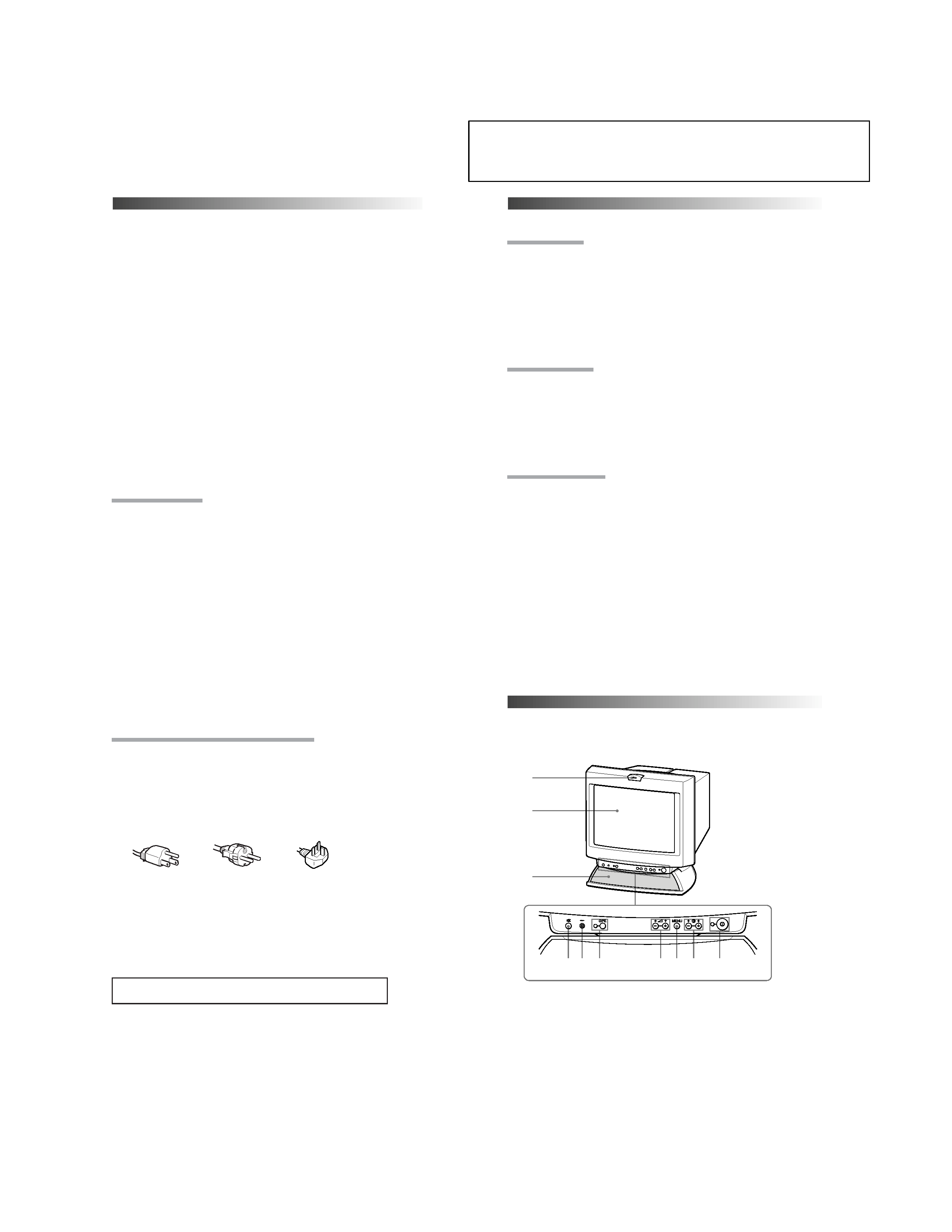
Functions of Controls
Functions of Controls
1
2
3
4
5
6
7
8
9
!º
Microphone
Screen
Stereo speakers
¤
Mute button
?
Reset switch
GPE button and
indicator
.
Volume +/
buttons
MENU button
>
+/ Contrast
buttons
U
Power switch
and indicator
--
--
--
Mutes sound (page 20).
Resets adjustments to factory setting (page 30).
Sets GPE mode (page 31).
Adjust speaker volume (page 19). Use to select
items in an OSD.
Displays the OSD menu.
Adjust picture contrast (page 21). Use to adjust
items in an OSD.
Turns the display on and off.
CPD-101VS is used for illustration purposes throughout this manual.
Front
1
45 6
7 8 9
!º
2
3