Operating Instructions
Owner's Record
The model and serial numbers are located on the rear of the system. Record the serial
number in the space provided below. Refer to them whenever you call upon your Sony
dealer regarding this product.
Model No.
Serial No.
Micro Hi-Fi
Component
System
3-867-817-12(1)
©1999 Sony Corporation
CMT-LS1
2
WARNING
To prevent fire or shock hazard, do not
expose the unit to rain or moisture.
To avoid electrical shock, do not open the cabinet.
Refer servicing to qualified personnel only.
Do not install the appliance in a confined space,
such as a bookcase or built-in cabinet.
This appliance is
classified as a CLASS
1 LASER product. The
CLASS 1 LASER
PRODUCT
MARKING is located
on the rear exterior.
NOTICE FOR THE CUSTOMERS IN
THE U.S.A.
This symbol is intended to alert
the user to the presence of
uninsulated "dangerous voltage"
within the product's enclosure
that may be of sufficient
magnitude to constitute a risk of
electric shock to persons.
This symbol is intended to alert
the user to the presence of
important operating and
maintenance (servicing)
instructions in the literature
accompanying the appliance.
CAUTION
The use of optical instruments with this product will
increase eye hazard.
The shielded interface cable recommended in this
manual must be used with this equipment in order to
comply with limits for a digital device pursuant to
Subpart B of Part 15 FCC Rules.
INFORMATION
This equipment has been tested and found to comply
with the limits for a Class B digital device, pursuant
to Part 15 of the FCC Rules. These limits are
designed to provide reasonable protection against
harmful interference in a residential installation. This
equipment generates, uses, and can radiate radio
frequency energy and, if not installed and used in
accordance with the instructions, may cause harmful
interference to radio communications. However, there
is no guarantee that interference will not occur in a
particular installation. If this equipment does cause
harmful interference to radio or television reception,
which can be determined by turning the equipment
off and on, the user is encouraged to try to correct the
interference by one or more of the following
measures:
Reorient or relocate the receiving antenna.
Increase the separation between the equipment and
receiver.
Connect the equipment into an outlet on a circuit
different from that to which the receiver is
connected.
Consult the dealer or an experienced radio/TV
technician for help.
CAUTION
You are cautioned that any changes or modifications
not expressly approved in this manual could void
your authority to operate this equipment.
Note to CATV system installer:
This reminder is provided to call CATV system
installer's attention to Article 82040 of the NEC that
provides guidelines for proper grounding and, in
particular, specifies that the cable ground shall be
connected to the grounding system of the building, as
close to the point of cable entry as practical.
NOTICE FOR THE CUSTOMERS IN
CANADA
CAUTION:
TO PREVENT ELECTRIC SHOCK, DO NOT USE
THIS POLARIZED AC PLUG WITH AN
EXTENSION CORD, RECEPTACLE OR OTHER
OUTLET UNLESS THE BLADES CAN BE FULLY
INSERTED TO PREVENT BLADE EXPOSURE.

3
Table of Contents
Getting Started
Step 1: Hooking up the system ................ 4
Step 2: Setting the time ............................ 9
Step 3: Presetting radio stations ............. 10
Opening the front panel ........................... 11
Basic Operations
Playing a CD ........................................... 12
Listening to the radio .............................. 14
The CD Player
Playing the CD tracks in random order
-- Shuffle Play ................................. 16
Programing the CD tracks
-- Program Play ............................... 17
Playing the CD tracks repeatedly
-- Repeat Play .................................. 18
Using the CD display .............................. 18
The Radio
Using the Radio Data System (RDS)
(European model only) ..................... 20
Sound Adjustment
Adjusting the sound ................................ 20
Generating a more dynamic sound .......... 21
Selecting the surround effect ................... 21
Timer
Falling asleep to music
-- Sleep Timer ................................. 22
Waking up to music
-- Daily Timer ................................. 23
Optional Components
Connecting audio components ................ 24
Listening to the sound of connected
components ....................................... 25
Recording a CD on the connected
component ........................................ 26
Connecting external antennas ................. 26
Additional Information
Precautions .............................................. 27
Troubleshooting ...................................... 28
Specifications .......................................... 30
Index ........................................... back cover
4
Getting Started
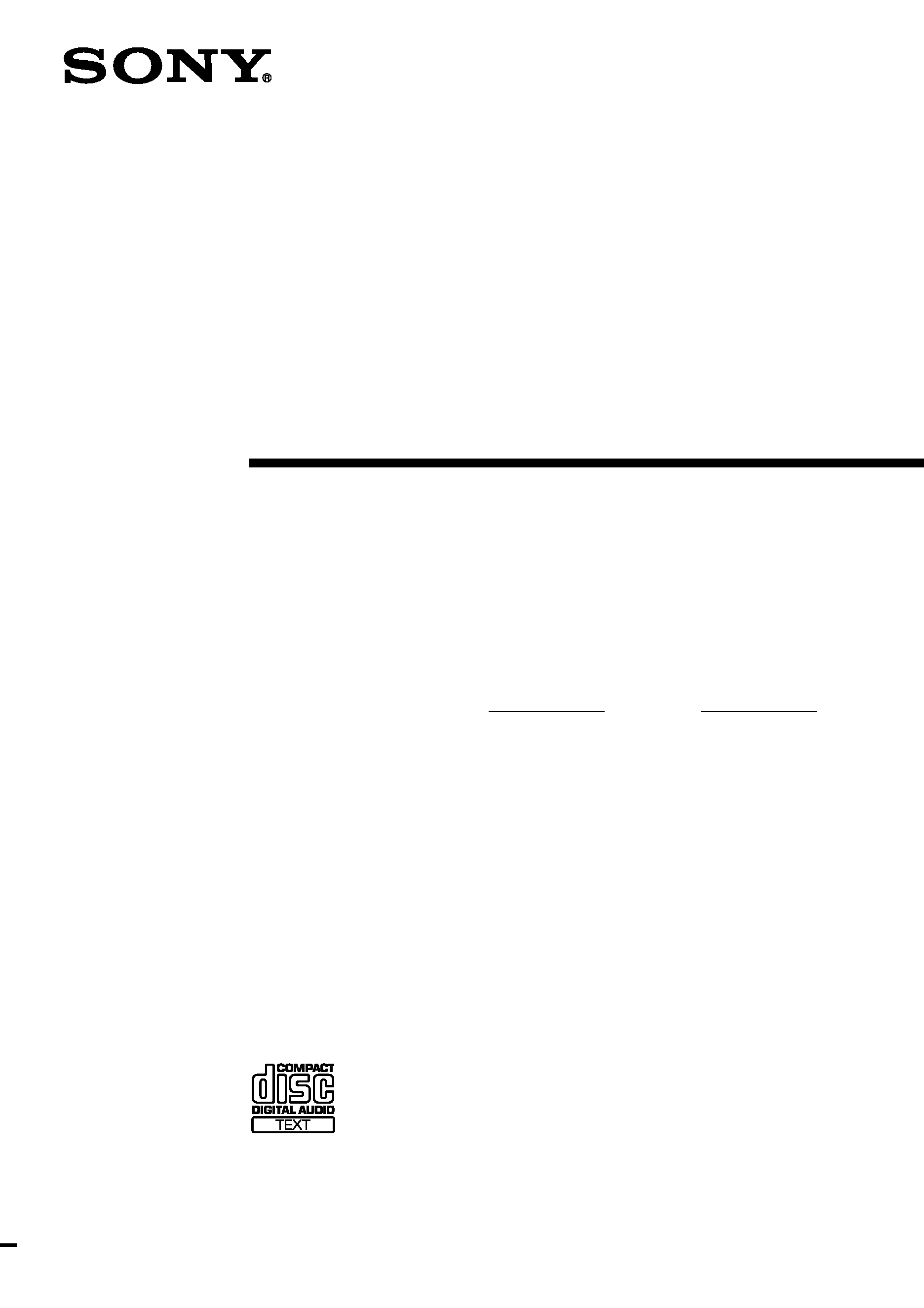
Step 1: Hooking up the system
Perform the following procedures 1 to 6 to hook up your system using the supplied cords and
accessories.
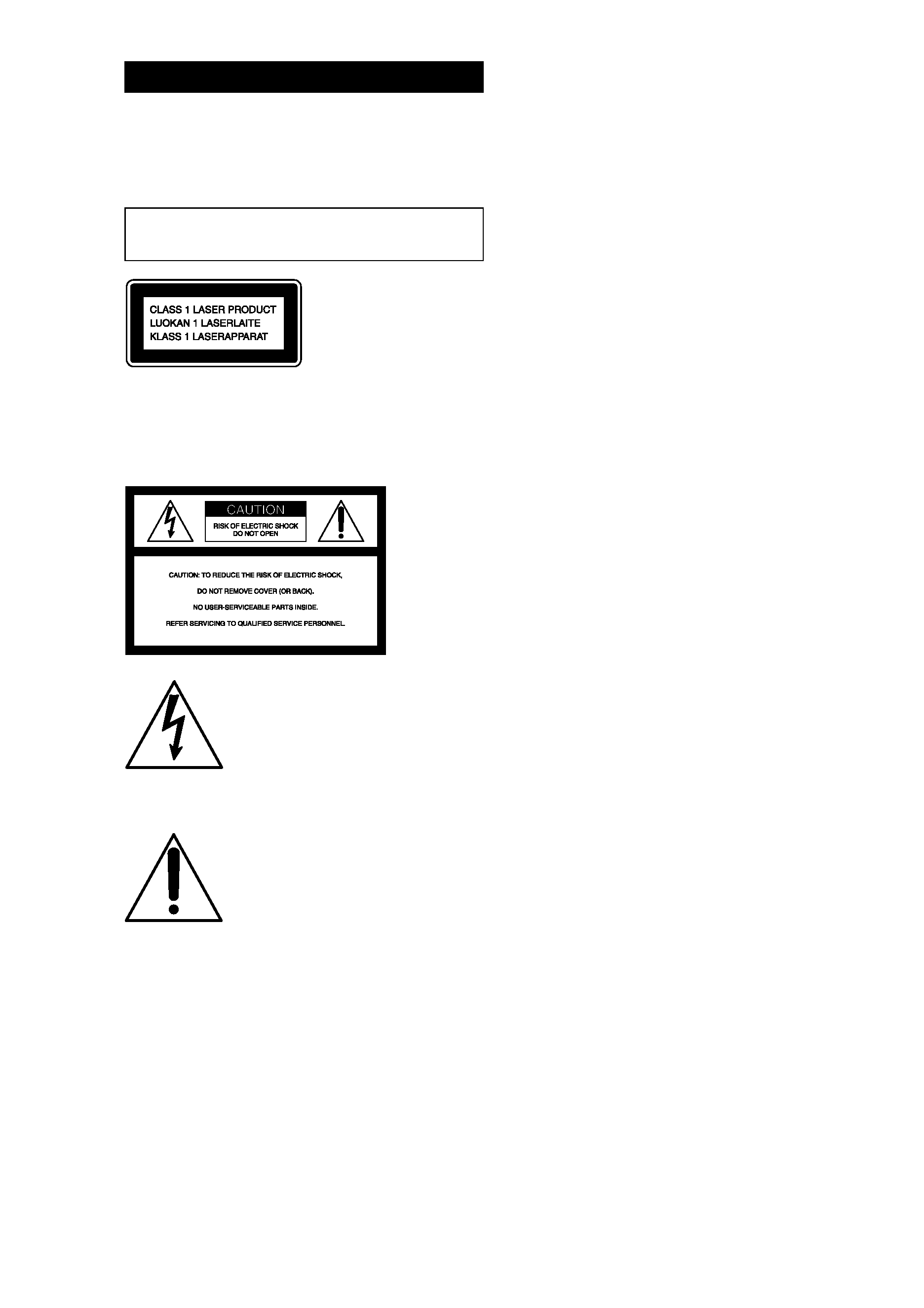
1 Attach the unit to the supplied desktop
stand with the supplied screws
(M4
× 14).
After mounting the unit on the stand, be
certain to pass the power cord through the
groove of the stand. If the stand is set up
without passing the power cord through the
groove, the weight of the unit will damage
the power cord, which could lead to electric
shock or fire.
Notes
· Be sure to attach the unit to the stand.
· Either mount both the left and right speakers, or
remove both of the speakers. Do not use the system
with only one speaker mounted.
Left speaker
Right speaker
FM antenna
AM loop antenna
5
Getting
Started
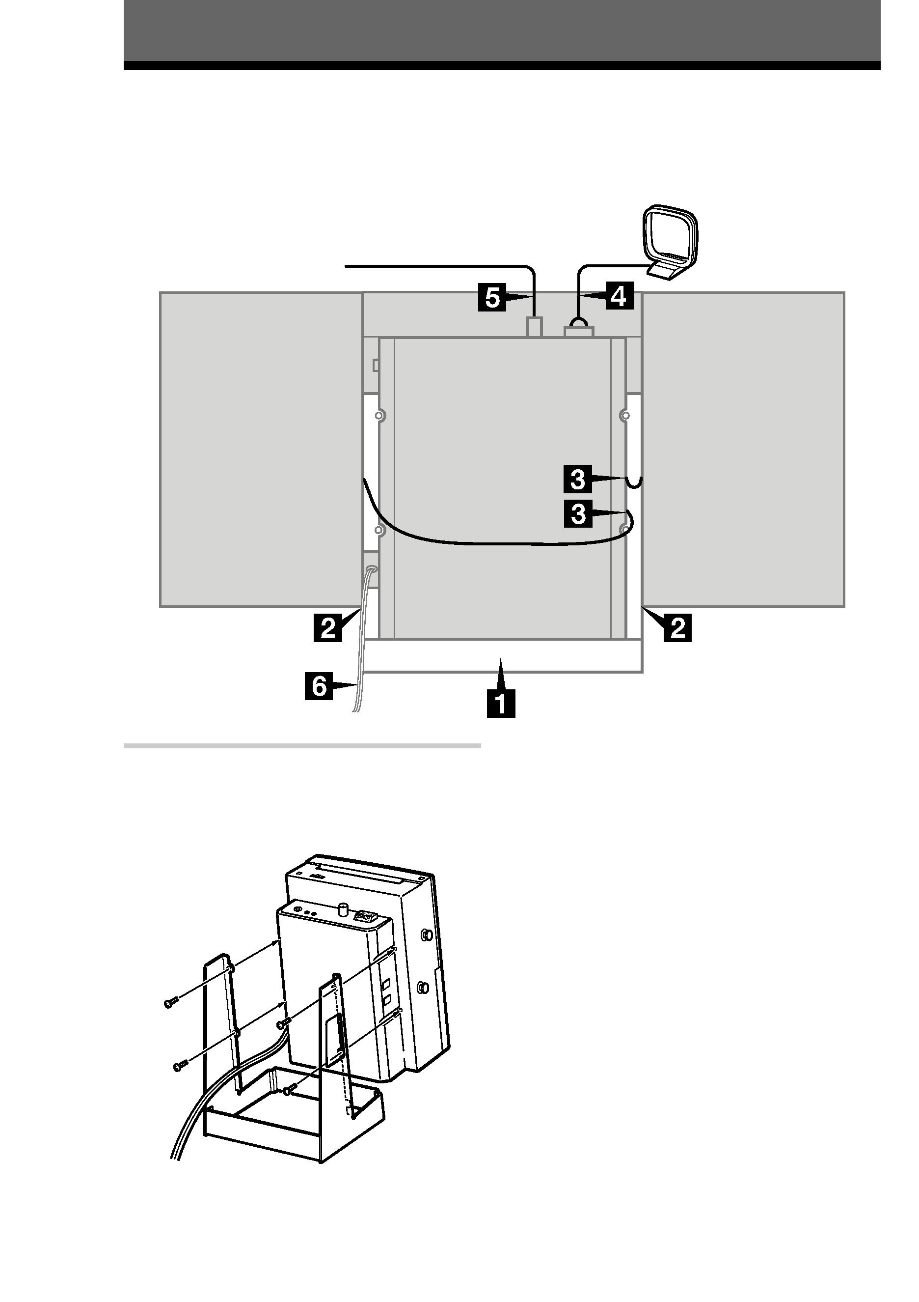
2 Attach the speakers.
Attach the speaker with the R cord to the
right side, and the speaker with the L cord to
the left side as viewed from the front of the
unit.
3 Connect the speakers.
Connect the speaker cords to the SPEAKER
jacks as shown below.
Notes
· Keep the speaker cords away from the antennas to
prevent noise.
· Be sure to connect both left and right speakers.
Otherwise, the sound will not be heard.
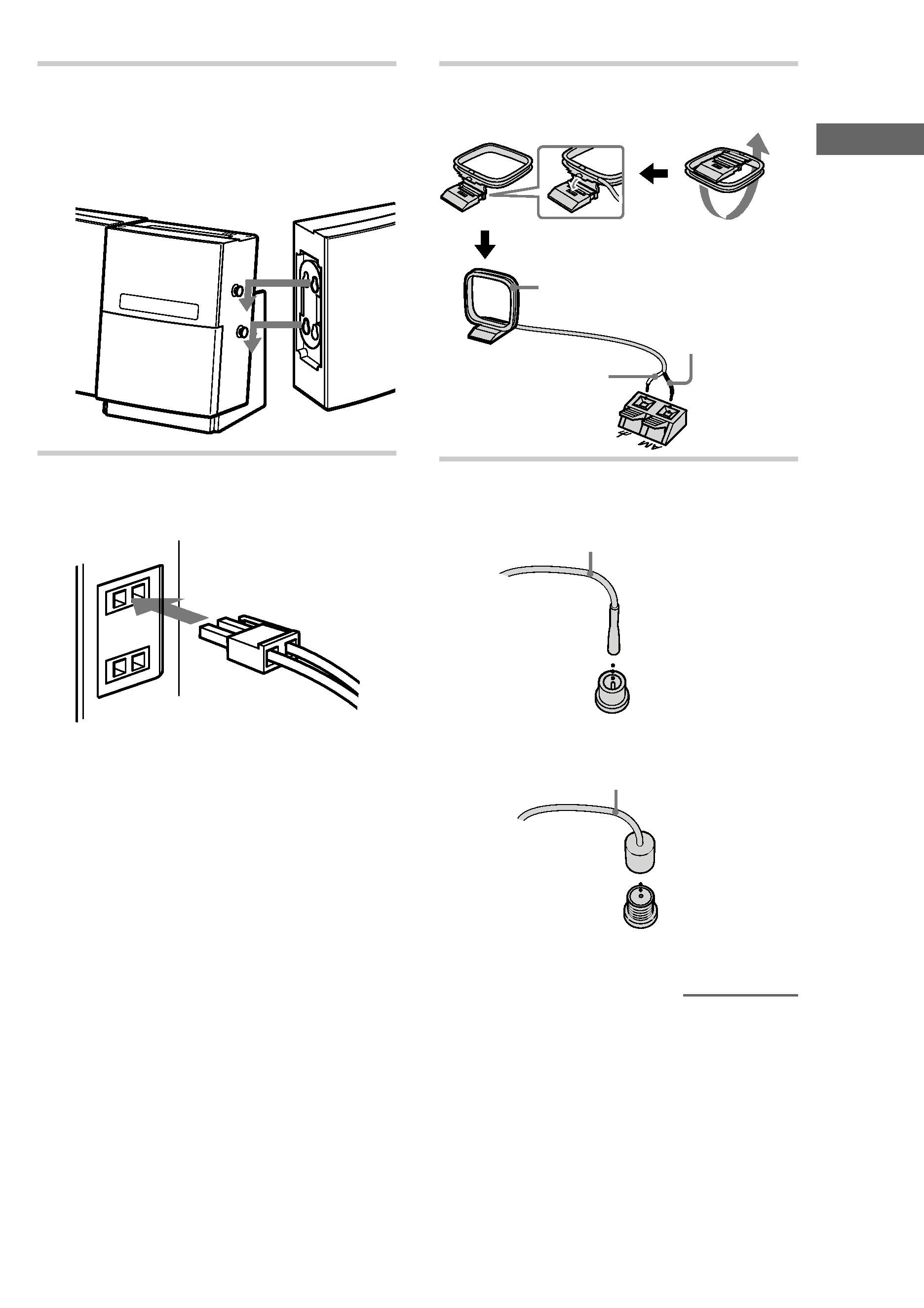
4 Connect the AM antenna.
Set up the AM loop antenna, then connect it.
5 Connect the FM antenna.
Jack type A
Extend the FM lead antenna horizontally
Jack type B
Extend the FM lead antenna horizontally
continued
White
Red
AM loop antenna