
Operating Instructions
Owner's Record
The model and serial numbers are located on the rear of the system. Record the serial
number in the space provided below. Refer to them whenever you call upon your Sony
dealer regarding this product.
Model No.
Serial No.
Micro HiFi
Component
System
3-867-342-13(1)
©1999 by Sony Corporation
CMT-ED2/ED2U

2
WARNING
To prevent fire or shock hazard, do not
expose the unit to rain or moisture.
To avoid electrical shock, do not open the cabinet.
Refer servicing to qualified personnel only.
Do not install the appliance in a confined space,
such as a bookcase or built-in cabinet.
This appliance is classified as
a CLASS 1 LASER product.
The CLASS 1 LASER
PRODUCT MARKING is
located on the rear exterior.
NOTICE FOR THE CUSTOMERS IN
THE U.S.A.
This symbol is intended to alert the
user to the presence of uninsulated
"dangerous voltage" within the
product's enclosure that may be of
sufficient magnitude to constitute a
risk of electric shock to persons.
This symbol is intended to alert the
user to the presence of important
operating and maintenance (servicing)
instructions in the literature
accompanying the appliance.
CAUTION
The use of optical instruments with this product will
increase eye hazard.
Note on CATV system installer:
This reminder is provided to call CATV system
installer's attention to Article 820-40 of the NEC that
provides guidelines for proper grounding and, in
particular, specifies that the cable ground shall be
connected to the grounding system of the building, as
close to the point of cable entry as practical.
INFORMATION
This equipment has been tested and found to comply
with the limits for a Class B digital device, pursuant
to Part 15 of the FCC Rules. These limits are
designed to provide reasonable protection against
harmful interference in a residential installation. This
equipment generates, uses, and can radiate radio
frequency energy and, if not installed and used in
accordance with the instructions, may cause harmful
interference to radio communications. However, there
is no guarantee that interference will not occur in a
particular installation. If this equipment does cause
harmful interference to radio or television reception,
which can be determined by turning the equipment
off and on, the user is encouraged to try to correct the
interference by one or more of the following
measures:
Reorient or relocate the receiving antenna.
Increase the separation between the equipment and
receiver.
Connect the equipment into an outlet on a circuit
different from that to which the receiver is
connected.
Consult the dealer or an experienced radio/TV
technician for help.
CAUTION
You are cautioned that any changes or modification
not expressly approved in this manual could void
your authority to operate this equipment.
NOTICE FOR THE CUSTOMERS IN
CANADA
CAUTION
TO PREVENT ELECTRIC SHOCK, DO NOT USE
THIS POLARIZED AC PLUG WITH AN
EXTENSION CORD, RECEPTACLE OR OTHER
OUTLET UNLESS THE BLADES CAN BE FULLY
INSERTED TO PREVENT BLADE EXPOSURE.
This system is equipped with the Dolby* B-type noise
reduction system.
* Dolby noise reduction manufactured under license
from Dolby Laboratories Licensing Corporation.
"DOLBY" and the double-D symbol ; are
trademarks of Dolby Laboratories Licensing
Corporation.

3
* European model only
Table of Contents
Getting Started
Step 1: Hooking up the system ................ 4
Step 2: Setting the time ............................ 7
Step 3: Presetting radio stations -- Preset .. 9
Connecting optional components ............ 10
Basic Operations
Playing a CD -- Normal Play ................. 13
Recording from a CD to a tape
-- CD Synchro Recording ............... 14
Listening to the radio -- Preset Tuning .. 16
Recording from the radio ........................ 17
Playing a tape .......................................... 18
The CD Player
Checking the remaining playing time on the
CD .................................................... 20
Playing CD tracks repeatedly
-- Repeat Play .................................. 20
Playing CD tracks in random order
-- Shuffle Play ................................. 21
Playing CD tracks in a favorite order
Program Play ............................... 22
The Tape Deck
Recording to a tape manually .................. 23
Recording your favorite CD tracks to a tape
-- Program Edit ................................ 24
Sound Adjustment
Generating a more dynamic sound .......... 26
Selecting the sound mode ....................... 26
Other Features
Using the Radio Data System (RDS)* .... 27
Falling asleep to music -- Sleep Timer .. 27
Waking up to music -- Daily Timer ....... 28
Timer-activated recording of radio
programs -- REC Timer .................. 29
Additional Information
Precautions .............................................. 31
Troubleshooting ...................................... 32
Specifications .......................................... 34
Parts identification for the remote ........... 36
Index .......................................... Back cover
4
Getting Started
Step 1: Hooking up the system
Follow steps 1 through 6 of the procedure below to hook up your system using the supplied cords and
accessories.
The speaker grille design differs somewhat from that of the U.S. and other models.
The U.S. model is used here for illustration purposes.
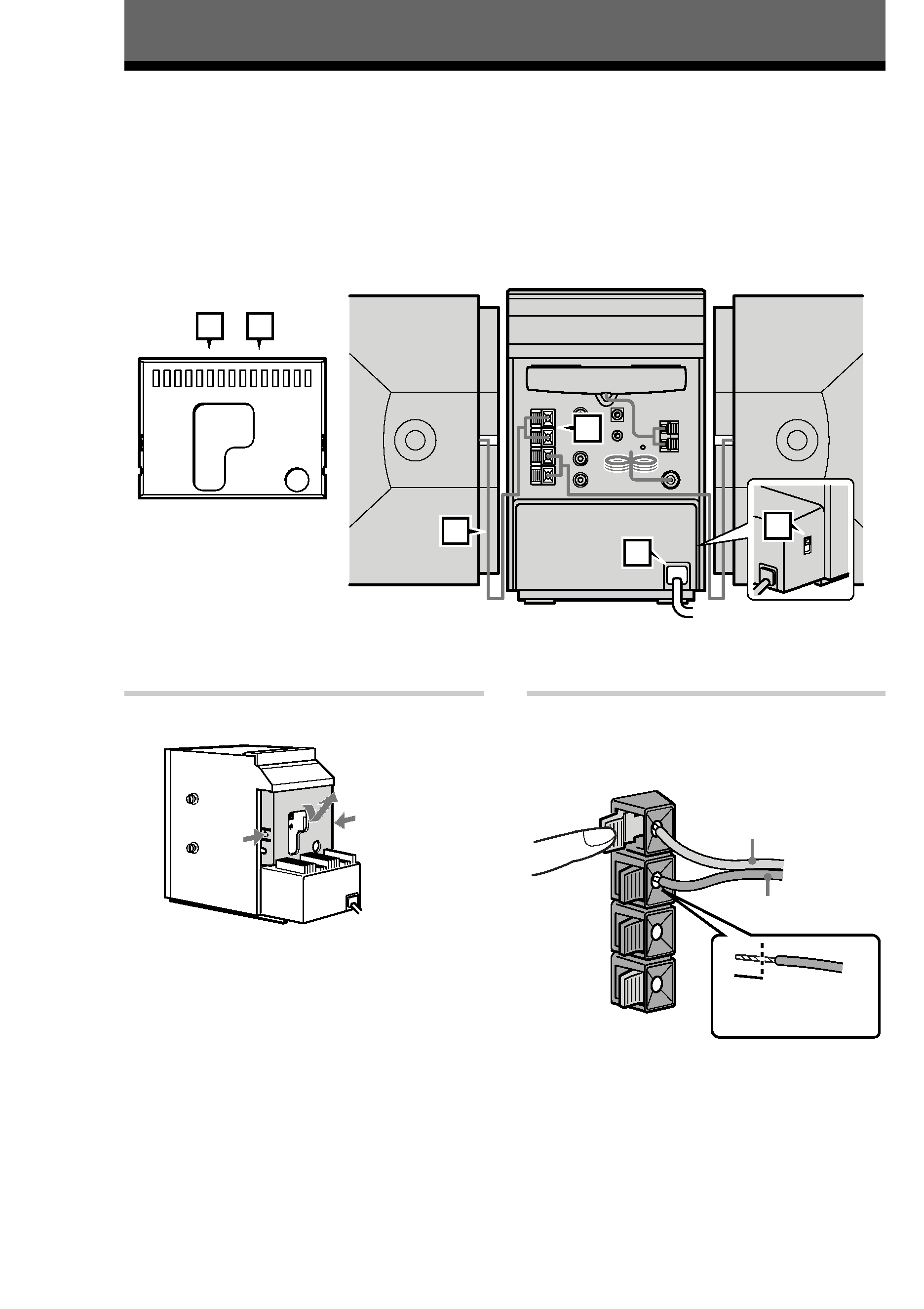
1 Remove the rear cover.
U
Push in on the tabs, pull downward,
and then lift off
2 Connect the speakers.
1 Connect the right and left speaker cords to
the SPEAKER terminals as shown below.
3
L
#
#
R
3
Note
Keep the speaker cords away from the
antennas to prevent noise.
U
3
4
1
2
5
6
Right speaker
Left speaker
Rear cover
Gray (3)
Black (#)
Insert this
portion
5
Getting
Started
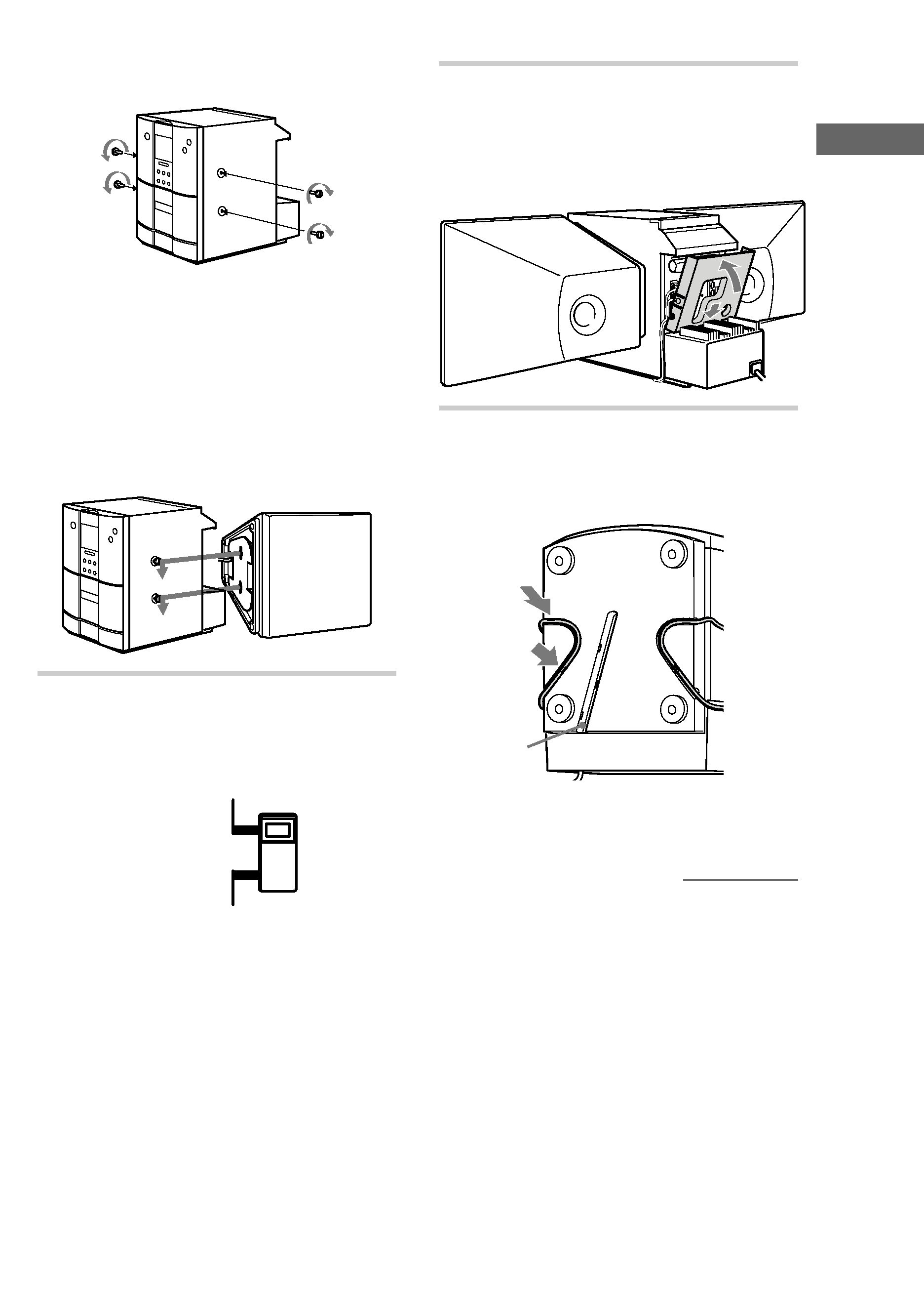
2 Fasten the four screws to both sides of the
unit.
+
3 Attach the speakers.
Facing the front of the unit, attach the
speaker connected to the SPEAKER R
terminals onto the right side of the unit
and the speaker connected to the
SPEAKER L terminals onto the left side
of the unit.
Afterwards, push down on the speakers to
make sure they are securely fastened to the
unit.
+
3 For models with a voltage selector, set
VOLTAGE SELECTOR to the local
power line voltage.
VOLTAGE
SELECTOR
110-120V
220-240V
4 After making sure that the cords are
correctly and securely connected,
reinstall the rear cover.
Pass the speaker cords through the holes on
both sides of the rear cover.
U
5 Turn the unit upside down while
holding the glass door firmly with your
hand, then set the speaker cord into the
groove at the bottom of the unit.
*
* This groove is used to hold the power cord
when the optional stand is attached.
continued