CMT-CQ1
US Model
Canadian Model
AEP Model
UK Model
E Model
Australian Model
SERVICE MANUAL
MICRO HI-FI COMPONENT SYSTEM
Sony Corporation
Home Audio Company
Published by Sony Engineering Corporation
9-877-322-01
2003E1600-1
© 2003.05
· CMT-CQ1 is composed of following models.
As for the service manual, it is issued for each component
model, then, please refer to them.
SPECIFICATIONS
Ver 1.0 2003. 05
COMPONENT MODEL NAME
COMPACT DISK DECK
RECEIVER SYSTEM
SPEAKER SYSTEM
PARTS LIST
CMT-CQ1
HCD-CQ1
SS-CCQ1
Part No.
Description
Remark
ACCESSORIES
************
1-477-884-11 COMMANDER, STANDARD (RM-SCQ1)(FOR WHITE)
1-477-884-21 COMMANDER, STANDARD (RM-SCQ1)(FOR BLACK)
1-501-374-72 ANTENNA, LOOP (AM)
0 1-770-019-11 ADAPTER CONVERSION 3P(UK,HK)
1-793-184-22 CONNECTOR (F TYPE ADAPTOR)(FM)
4-228-952-11 COVER, BATTERY (FOR RM-SCQ1)(FOR WHITE)
4-228-952-21 COVER, BATTERY (FOR RM-SCQ1)(FOR BLACK)
4-244-819-11 MANUAL, INSTRUCTION (ENGLISH)
(US,CND,AEP,UK,HK,SP,TW,AUS)
4-244-819-21 MANUAL, INSTRUCTION (FRENCH)(US,CND)
4-244-819-31 MANUAL, INSTRUCTION (FRENCH,SPANISH)(AEP,SP,MX)
4-244-819-41 MANUAL, INSTRUCTION
(GERMAN,DUTCH,ITALIAN,SWEDISH,POLISH)(AEP)
4-244-819-51 MANUAL, INSTRUCTION (TRADITIONAL CHINESE)
(HK,SP,TW)
4-244-819-61 MANUAL, INSTRUCTION (KOREAN)(KR)
The components identified by
mark 0 or dotted line with mark
0 are critical for safety.
Replace only with part number
specified.
Les composants identifiés par
une marque 0 sont critiques
pour la sécurité.
Ne les remplacer que par une
pièce portant le numéro spécifié.
General
Power requirements
North American model:
120 V AC, 60 Hz
European model:
230 V AC, 50/60 Hz
Australian model:
230 V AC, 50/60 Hz
Mexican model:
120 V AC, 60 Hz
Korean model:
220 V AC, 60 Hz
Taiwan model:
120 V AC, 50/60 Hz
Other models:
230 V AC, 50/60 Hz
Power consumption
North American and Mexican models:
40 watts
European model:
40 watts
0.35 watts (in the standb y
mode)
Other models:
40 watts
Dimensions (w/h/d)
Approx. 190
× 120 × 235
mm incl. projecting parts
and controls
Mass
Approx. 3.5 kg
Supplied accessories
Remote (1)
R6 (size AA) batteries (2)
AM loop antenna (1)
FM lead antenna (1)
Design and specifications are subject to change
without notice.
Hong Kong model:
220 V AC, 50/60 Hz
MX : Mexican model.
SP
: Singapore model.
TW : Taiwan model.
· Abbreviation
AUS : Australian model.
CND : Canadian model.
HK : Hong Kong model.
KR
: Korean model.

CMT-CQ1
REVISION HISTORY
Clicking the version allows you to jump to the revised page.
Also, clicking the version at the upper right on the revised page allows you to jump to the next revised
page.
Ver.
Date
Description of Revision
1.0
2003.05
New
HCD-CQ1
US Model
Canadian Model
AEP Model
UK Model
E Model
Australian Model
SERVICE MANUAL
MICRO Hi-Fi COMPONENT SYSTEM
Sony Corporation
Personal Audio Company
Published by Sony Engineering Corporation
9-877-323-04
2005A16-1
© 2005.01
Ver. 1.3 2005.01
SPECIFICATIONS
This set is the tuner, CD and amplifier
section in CMT-CQ1.
Model Name Using Similar Mechanism
NEW
CD Mechanism Type
CDM76-K6BD44S
Base Unit Type
BU-K6BD44S
Optical Pick-up Type
KSS-213D/Q-RP
-- Continued on next page --
Main unit
Amplifier section
AUDIO POWER SPECIFICATIONS:
(U.S.A. model only)
POWER OUTPUT AND TOTAL HARMONIC
DISTORTION:
With 6-ohm loads, both channels driven, from 120 -
10,000 Hz; rated 10 watts per channel minimum RMS
power, with no more than 10% total harmonic
distortion from 250 milliwatts to rated output.
North American model:
Continuous RMS power output (reference):
10 + 10 W
(6 ohms at 1 kHz, 10%
THD)
European and Australian models:
DIN power output (rated): 8 + 8 W
(6 ohms at 1 kHz, DIN)
Continuous RMS power output (reference):
10 + 10 W
(6 ohms at 1 kHz, 10%
THD)
Music power output (reference):
20 + 20 W
Other models:
The following measured at AC 220 V, 50/60 Hz
DIN power output (rated): 8 + 8 W
(6 ohms at 1 kHz, DIN)
Continuous RMS power output (reference):
10 + 10 W
(6 ohms at 1 kHz, 10%
THD)
The following measured at AC 240 V, 50/60 Hz
DIN power output (rated): 8 + 8 W
(6 ohms at 1 kHz, DIN)
Continuous RMS power output (reference):
10 + 10 W
(6 ohms at 1 kHz, 10%
THD)
Inputs
PC/MD/TAPE IN (stereo minijack):
Sensitivity 1.3 (MD)/
820mV (PC/TAPE)
impedance 47 kilohms
Outputs
PC/MD/TAPE OUT (stereo minijack):
Sensitivity 250 mV,
impedance 1 kilohm
PHONES (stereo minijack):
Accepts headphones with
an impedance of 8 ohms or
more
SPEAKER:
Accepts impedance of 6 to
16 ohms.
CD player section
System
Compact disc and digital
audio system
LaserSemiconductor laser
(
=780 nm)
Emission duration:
continuous
Frequency response
2 Hz 20 kHz
Tuner section
FM stereo, FM/AM superheterodyne tuner
FM tuner section
Tuning range
North American model:
87.5 108.0 MHz (100-
kHz step)
Other models:
87.5 108.0 MHz (50-kHz
step)
Antenna
FM lead antenna
Antenna terminals
75 ohms unbalanced
Intermediate frequency
10.7 MHz
AM tuner section
Tuning range
Pan-American model:
530 1,710 kHz
(with the tuning interval
set at 10 kHz)
531 1,710 kHz
(with the tuning interval
set at 9 kHz)
European model:
531 1,602 kHz
(with the tuning interval
set at 9 kHz)
Other models:
530 1,710 kHz
(with the tuning interval
set at 10 kHz)
531 1,602 kHz
(with the tuning interval
set at 9 kHz)
Antenna
AM loop antenna, external
antenna terminal
Intermediate frequency
450 kHz
CD
SECTION
2
HCD-CQ1
After correcting the original service problem, perform the
following safety checks before releasing the set to the customer:
Check the antenna terminals, metal trim, "metallized" knobs, screws,
and all other exposed metal parts for AC leakage. Check leakage as
described below.
LEAKAGE
The AC leakage from any exposed metal part to earth ground and
from all exposed metal parts to any exposed metal part having a
return to chassis, must not exceed 0.5 mA (500 microamperes).
Leakage current can be measured by any one of three methods.
1.
A commercial leakage tester, such as the Simpson 229 or RCA
WT-540A. Follow the manufacturers' instructions to use these
instruments.
2.
A battery-operated AC milliammeter. The Data Precision 245
digital multimeter is suitable for this job.
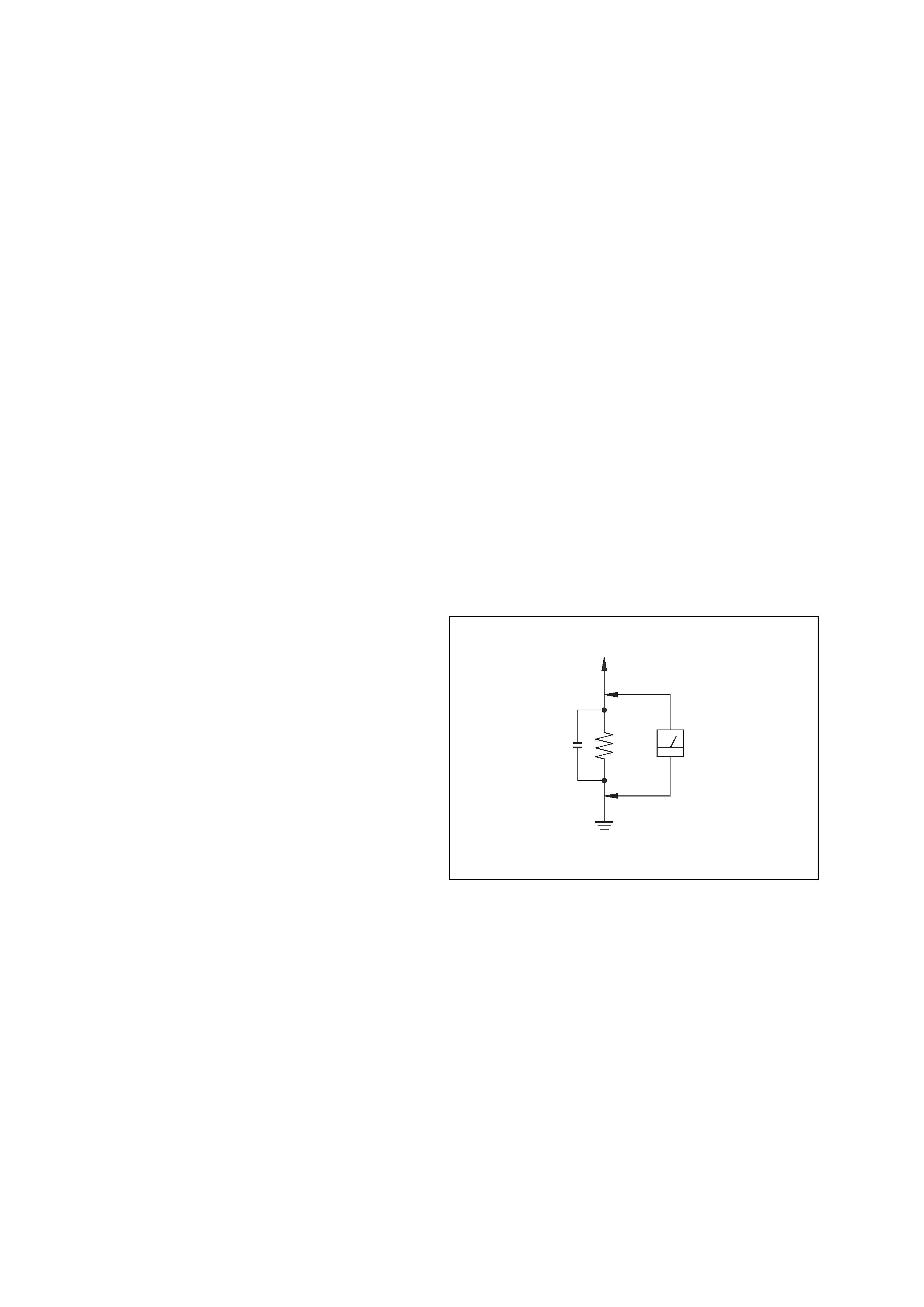
3.
Measuring the voltage drop across a resistor by means of a
VOM or battery-operated AC voltmeter. The "limit" indication
is 0.75 V, so analog meters must have an accurate low-voltage
scale. The Simpson 250 and Sanwa SH-63Trd are examples of
a passive VOM that is suitable. Nearly all battery operated
digital multimeters that have a 2V AC range are suitable. (See
Fig. A)
SAFETY CHECK-OUT
To Exposed Metal
Parts on Set
0.15 µF
1.5 k
AC
Voltmeter
(0.75 V)
Earth Ground
Fig. A. Using an AC voltmeter to check AC leakage.
General
Power requirements
North American model:
120 V AC, 60 Hz
European model:
230 V AC, 50/60 Hz
Australian model:
230 @
30
V AC, 50/60 Hz
Mexican model:
120 V AC, 60 Hz
Korean model:
220 V AC, 60 Hz
Taiwanese model:
120 V AC, 50/60 Hz
Other models:
2
V AC, 50/60 Hz
Power consumption
North American and Mexican models:
40 watts
European model:
40 watts
0.25 watts (in the standby
mode)
Other models:
40 watts
Dimensions (w/h/d)
Approx. 190
× 120 × 235
mm incl. projecting parts
and controls
Mass
Approx. 3.5 kg
Design and specifications are subject to change
without notice.
Ver 1.1 2003.06

3
HCD-CQ1
TABLE OF CONTENTS
1. SERVICING NOTES ······················································· 4
2. GENERAL ·········································································· 6
3. DISASSEMBLY
3-1. Panel (Back) ···································································· 9
3-2. Panel (Top) Assy ··························································· 10
3-3. PANEL Board ······························································· 11
3-4. CD Mechanism Deck (CDM76-K6BD44S) ················· 11
3-5. JACK Board, REG Board ············································· 12
3-6. Bearing Assy, Bushing (Guide A) ································· 12
3-7. Tuner (FM/AM) ···························································· 13
3-8. POWER Board ······························································ 13
3-9. REMOCON Board, Panel (Front) Assy ························ 14
3-10. CONTROL Board ······················································· 14
3-11. Optical Pick-Up (KSM-213DCP/Z-NP) ····················· 15
3-12. BD Board ···································································· 15
3-13. KSS-213D/Q-RP ························································· 16
3-14. Slider (R), Slider (L) ··················································· 16
3-15. Tray ············································································· 17
3-16. LOADING Board, Gear (P), Gear (M) ······················· 17
4. TEST MODE ···································································· 18
5. ELECTRICAL ADJUSTMENTS ······························· 20
6. DIAGRAMS
6-1. Note for Printed Wiring Boards and
Schematic Diagrams ···················································· 21
6-2. Block Diagram CD Section ··································· 22
6-3. Block Diagram MAIN Section ······························ 23
6-4. Printed Wiring Board BD Section ························· 24
6-5. Schematic Diagram BD Section ···························· 25
6-6. Printed Wiring Board
PANEL Section (Component Side) ······················· 26
6-7. Printed Wiring Board
PANEL Section (Conductor Side) ························· 27
6-8. Printed Wiring Board
CONTROL Section (Component Side) ················· 28
6-9. Printed Wiring Board
CONTROL Section (Conductor Side) ··················· 29
6-10. Schematic Diagram CONTROL Section ··············· 30
6-11. Printed Wiring Board
POWER Section (Component Side) ······················ 31
6-12. Printed Wiring Board
POWER Section (Conductor Side) ······················· 32
6-13. Schematic Diagram POWER Section ··················· 33
6-14. IC Block Diagrams ······················································ 34
6-15. IC Pin Function Description ········································ 35
7. EXPLODED VIEWS
7-1. Panel (Top) Section ····················································· 37
7-2. Chassis Section-1 ························································ 38
7-3. Chassis Section-2 ························································ 39
7-4. Chassis Section-3 ························································ 40
7-5. CD Mechanism Deck Section-1
(CDM76-K6BD44S) ··················································· 41
7-6. CD Mechanism Deck Section-2
(CDM76-K6BD44S) ··················································· 42
7-7. KSM-213DCP/Z-NP ··················································· 43
8. ELECTRICAL PARTS LIST ······································· 44