Ver 1.0 2001.02
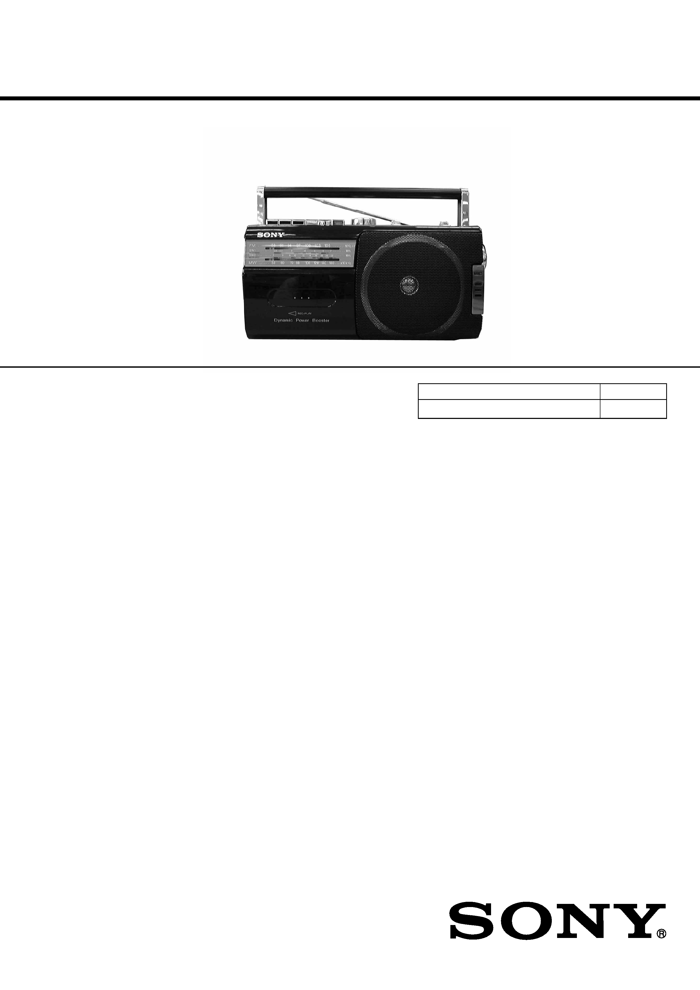
CFM-S1
SERVICE MANUAL
RADIO CASSETTE-CORDER
SPECIFICATIONS
E Model
9-873-068-11
2001B0200-1
© 2001.2
Sony Corporation
Audio Entertainment Group
General Engineering Dept.
Model Name Using Similar Machanism
NEW
Tape Transport Mechanism Type
MF-M20-117
· Frequency range
FM: Saudi Arabia: 87.6 - 107 MHz
Other models: 87.6 - 108 MHz
MW: 530 - 1 605 kHz
SW1: 2.3 - 7 MHz
SW2: 7 - 22 MHz
· Aerials FM/SW: Telescopic aerial
MW: Built-in ferrite bar aerial
· Recording system 2-track 1 channel mono
· Frequency response 80 - 8 000 Hz
· Speaker Full range: 12 cm (4 3/4 inches) dia., 6
, cone
type (1)
· Outputs Earphones jack
For 8
impedance earphones
· Maximum power output 1.4 W
· Power requirements 110 - 120, 220 - 240 V AC
selectable, 50/60 Hz
6 V DC, 4 R20 (size D) batteries
· Power consumption AC 8 W
· Battery life
FM recording: Sony R20P: approx. 18 h
Sony alkaline LR20: approx. 50 h
Tape playback: Sony R20P: approx. 12 h
Sony alkaline LR20: approx. 30 h
· Dimensions Approx. 287 X 147 X 110 mm (w/h/d)
(11 3/8 X 5 7/8 X 4 4/8 inches) (incl. projecting parts)
· Mass (incl. batteries) Approx. 2 kg (4 lb. 7 oz)
· Supplied accessory Mains lead (1)
Design and specifications are subject to change without
notice.
2
CFM-S1
TABLE OF CONTENTS
Specifications ........................................................................... 1
1.
GENERAL
Location and Function of Controls .................................... 2
2.
DISASSEMBLY
2-1. Cabinet (Front) ASSY, "Cabi, rear" ........................... 3
2-2. MD ASSY ................................................................... 3
2-3. Record/Playback Head (HRP101),
Reel/Capstan Motor (M101),Belt ............................... 3
2-4. Jack Board, Main Board, Fine Tune Board ................ 4
2-5. Battery Terminal Board, Power Board, ...................... 4
2-6. Note on Instalation ...................................................... 5
2-7. Dial Pointer Setting .................................................... 5
3.
TEST MODE
3-1. Mechanical Adjustments ............................................. 6
3-2. Electrical Adjustments ................................................ 6
6.
DIAGRAMS ...................................................................... 9
4-1. Block Diagrams ........................................................ 10
4-2. Printed Wiring Boards .............................................. 11
4-3. Schematic Diagrams -Main Section (1/2) - ............. 12
4-4. Schematic Diagrams -Main Section (2/2) - ............. 13
5.
EXPLODED VIEWS
5-1. Front Cabinet Section ............................................... 16
5-2. Rear Cabinet Section ................................................ 17
5-3. Mechanism Deck Section-1(MF-M20-117) ............. 18
5-4. Mechanism Deck Section-2(MF-M20-117) ............. 19
6.
ELECTRICAL PARTS LIST ........................................ 20
SECTION 1
GENERAL
SAFETY-RELATED COMPONENT WARNING!!
COMPONENTS IDENTIFIED BY MARK
! OR DOTTED LINE WITH
MARK
!ON THE SCHEMATIC DIAGRAMS AND IN THE PARTS LIST
ARE CRITICAL TO SAFE OPERATION.
REPLACE THESE COMPONENTS WITH SONY PARTS WHOSE
PART NUMBERS APPEAR AS SHOWN IN THIS MANUAL OR IN
SUPPLEMENTS PUBLISHED BY SONY.
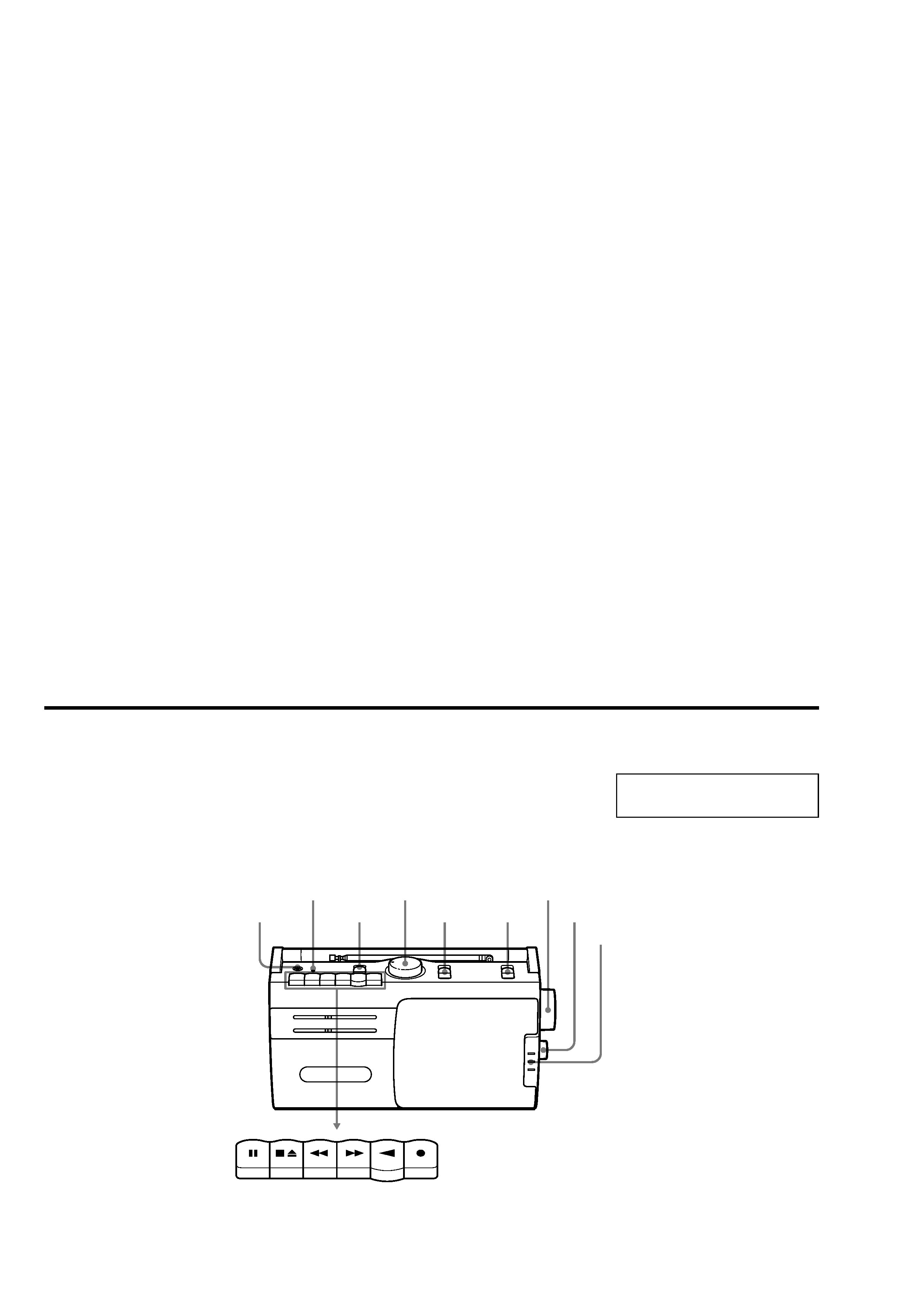
TUNING
PAUSE
STOP/EJECT
FF
REW
PLAY
REC
BAND
VOLUME
OPR/BATT
MIC
FINE TUNING
FUNCTION
@
DPB
This section is extracted from
instruction manual.
Location and Function of Controls
3
CFM-S1
1
2
Screws
+ BVTP 3X10
Chassis(B)
MD ASSY
pointer
Cabi, rear
SECTION 2
DISASSEMBLY
Note : Follow the disassembly procedure in the numerical order given.
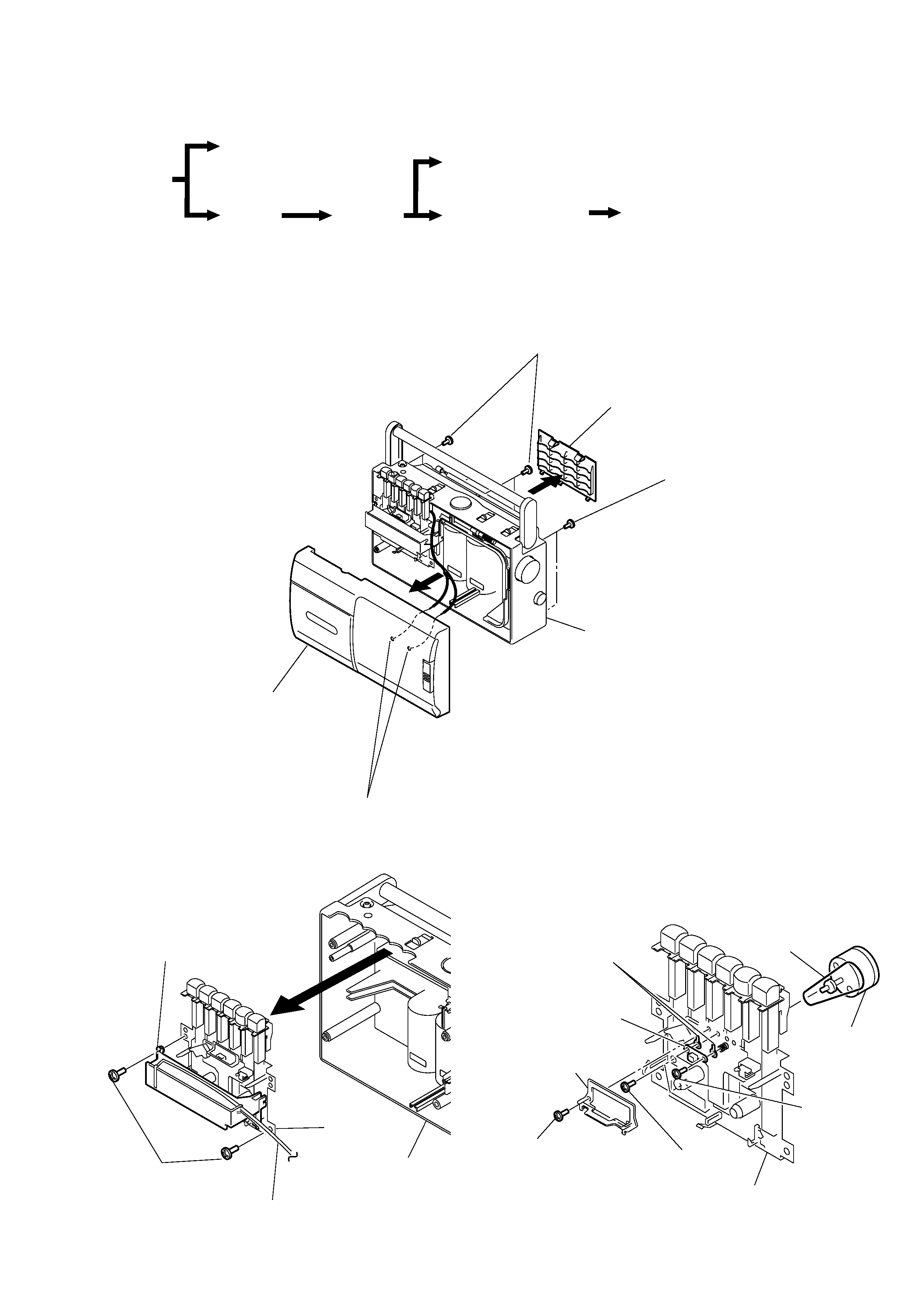
2-1. CABINET (FRONT) ASSY, "CABI, REAR"
2-2. MD ASSY
· The equipment can be removed using the following procedure.
Set
Cabinet (front) ASSY
Cabi, rear
Jack board, Main board,
Fine tune board
Battery terminal board, Power board
MD ASSY
Record/playback head (HRP101),
Reel/capstan motor (M101), Belt
3
1
4 Remove solder (two places)
2 Screws + BVTP 3X14
2 Screws + BVTP 3X14
Lid, BATT
Cabinet(front) ASSY
Cabi, rear
2-3. RECORD/PLAYBACK HEAD (HRP101),
REEL/CAPSTAN MOTOR (M101), BELT
1Screws Tapping+B
MD ASSY
4Record/playback
head (HRP101)
7
Reel/capstan
motor (M101)
3Screws
+ PTT 2X 5
6Screws + P2X 5
8Belt
5Lug (T), plate
2Guide, tape
4
CFM-S1
2-4. JACK BOARD, MAIN BOARD, FINE TUNE BOARD
2-5. BATTERY TERMINAL BOARD, POWER BOARD
8
6
3
3
3
Chassis(A)
Main board
7Screws + BVTP 3X10
2Screw +BVTP 3X10
5Claw
Cabi, rear
Fine tune board
1
Knob(FT)
1
Knob(band)
1
Knob(function)
1
Knob(vol)
1
Knob(sound)
4Screw +BVTP 3X10
Jack board
1
Knob(tune)
Bracket(PWB)
6
2
4
Remove Solder
Cabi, rear
Power board
3
Remove solder
Battery terminal board
5
Screws + BVTP 3X10
1
Claw
5
CFM-S1
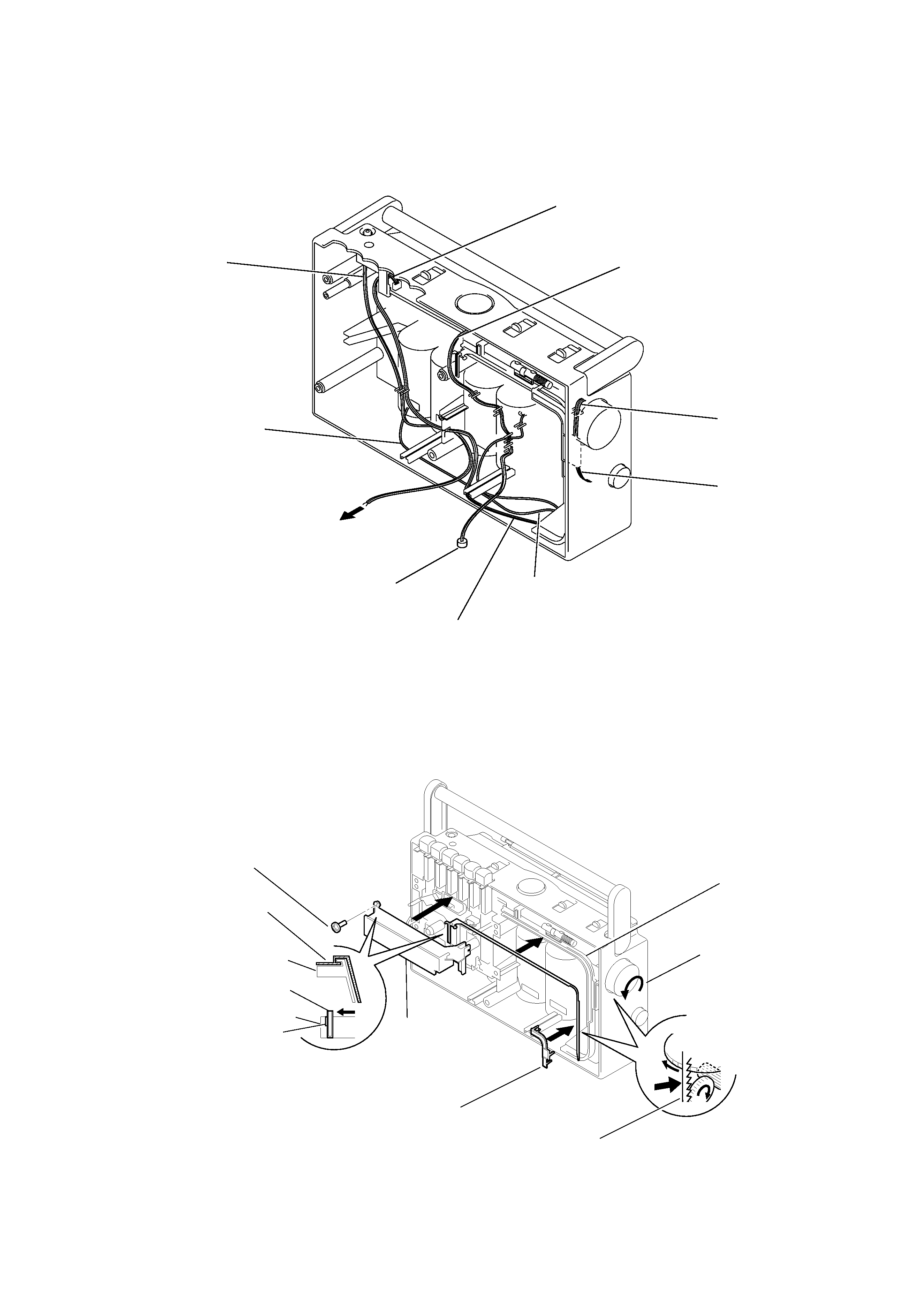
2-6. NOTE ON INSTALATION
To jack board
Power board (CN901)
Fine tune board (KH2)
Main board (KH1)
Main board (KH101)
Main board (KH102)
To battery terminal board
To speaker
(SP1)
MIC (ECM101)
Power board (KH901)
2-7. DIAL POINTER SETTING
Dress the lead wires as shown in figure.
1 Turn the knob(tune)
fully counterclockwise.
2 Fit the pointer to the
chassis(B).
5 Set the left side of the
pointer to the convex
portion (a) on the
chassis(B).
Pointer
Chassis(A)
Chassis(B)
Chassis(B)
6
6
3
6
Hold the left side of pointer,
then insert the gear section
of pointer to groove of chassis(A).
7Bracket(P)
4 Screw + BVTP 3X14
Pointer
Chassis(B)
Pointer
(a)