Ver 1.0 2001.03
CFM-20
SERVICE MANUAL
RADIO CASSETTE-CORDER
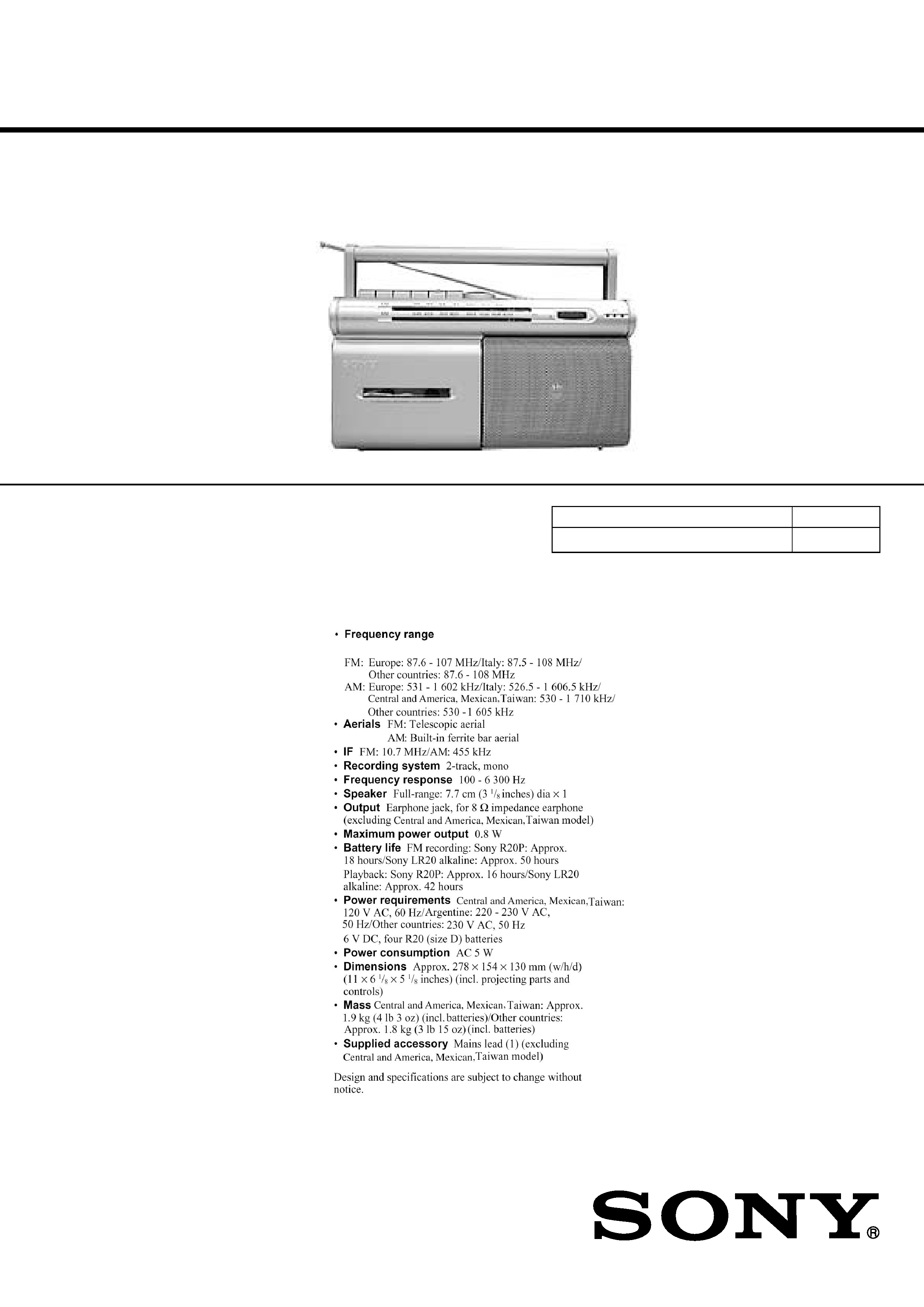
SPECIFICATIONS
AEP Model
UK Model
E Model
9-873-105-21
2001C0200-1
© 2001.3
Sony Corporation
Audio Entertainment Group
General Engineering Dept.
Model Name Using Similar Machanism
CFM-S1
Tape Transport Mechanism Type
MF-M20-117
2
CFM-20
TABLE OF CONTENTS
Specifications ........................................................................... 1
1.
GENERAL
Location and Function of Controls .................................... 2
2.
DISASSEMBLY
2-1. Cabinet (Front) Sub ASSY, Cabinet (Rear) ASSY .... 3
2-2. MD ASSY ................................................................... 3
2-3. Record/Playback Head (HRP101),
Reel/Capstan Motor (M101),Belt ............................... 4
2-4. Jack Board (AEP, UK, IT, CET, HK, SP, AR model)
Main Board ................................................................. 4
2-5. Batt (+) Board, Power Board
(AEP, UK, IT, CET, HK, SP, AR model) .................... 5
2-6. Batt (+) Board, Power Board
(C&SA, MX, TW model) ........................................... 5
3.
ADJUSTMENTS
3-1. Mechanical Adjustments ............................................. 7
3-2. Electrical Adjustments ................................................ 7
4.
DIAGRAMS
4-1. Block Diagrams ......................................................... 11
4-2. Printed Wiring Boards .............................................. 12
4-3. Schematic Diagrams -Main Section (1/2) - ............. 13
4-4. Schematic Diagrams -Main Section (2/2) - ............. 14
5.
EXPLODED VIEWS
5-1. Front Cabinet Section ............................................... 17
5-2. Rear Cabinet Section ................................................ 18
5-3. Mechanism Deck Section-1(MF-M20-117) ............. 19
5-4. Mechanism Deck Section-2(MF-M20-117) ............. 20
6.
ELECTRICAL PARTS LIST ........................................ 21
SECTION 1
GENERAL
SAFETY-RELATED COMPONENT WARNING!!
COMPONENTS IDENTIFIED BY MARK
! OR DOTTED LINE WITH
MARK
!ON THE SCHEMATIC DIAGRAMS AND IN THE PARTS LIST
ARE CRITICAL TO SAFE OPERATION.
REPLACE THESE COMPONENTS WITH SONY PARTS WHOSE
PART NUMBERS APPEAR AS SHOWN IN THIS MANUAL OR IN
SUPPLEMENTS PUBLISHED BY SONY.
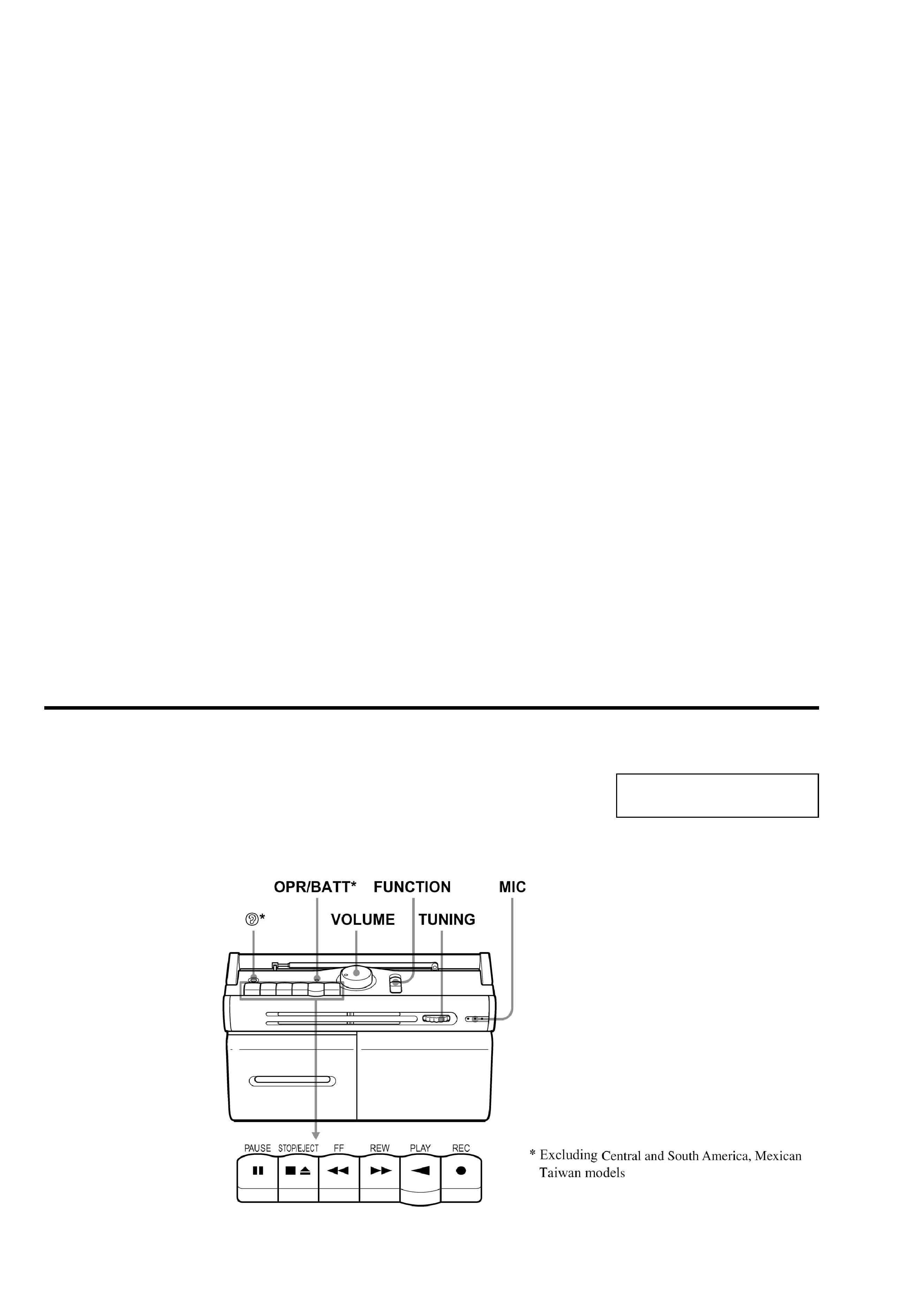
This section is extracted from
instruction manual.
Location and Function of Controls
Notes on chip component replacement
· Never reuse a disconnected chip component.
· Notice than the minus side of a tantalum capactior may be
damaged by heat.
3
CFM-20
SECTION 2
DISASSEMBLY
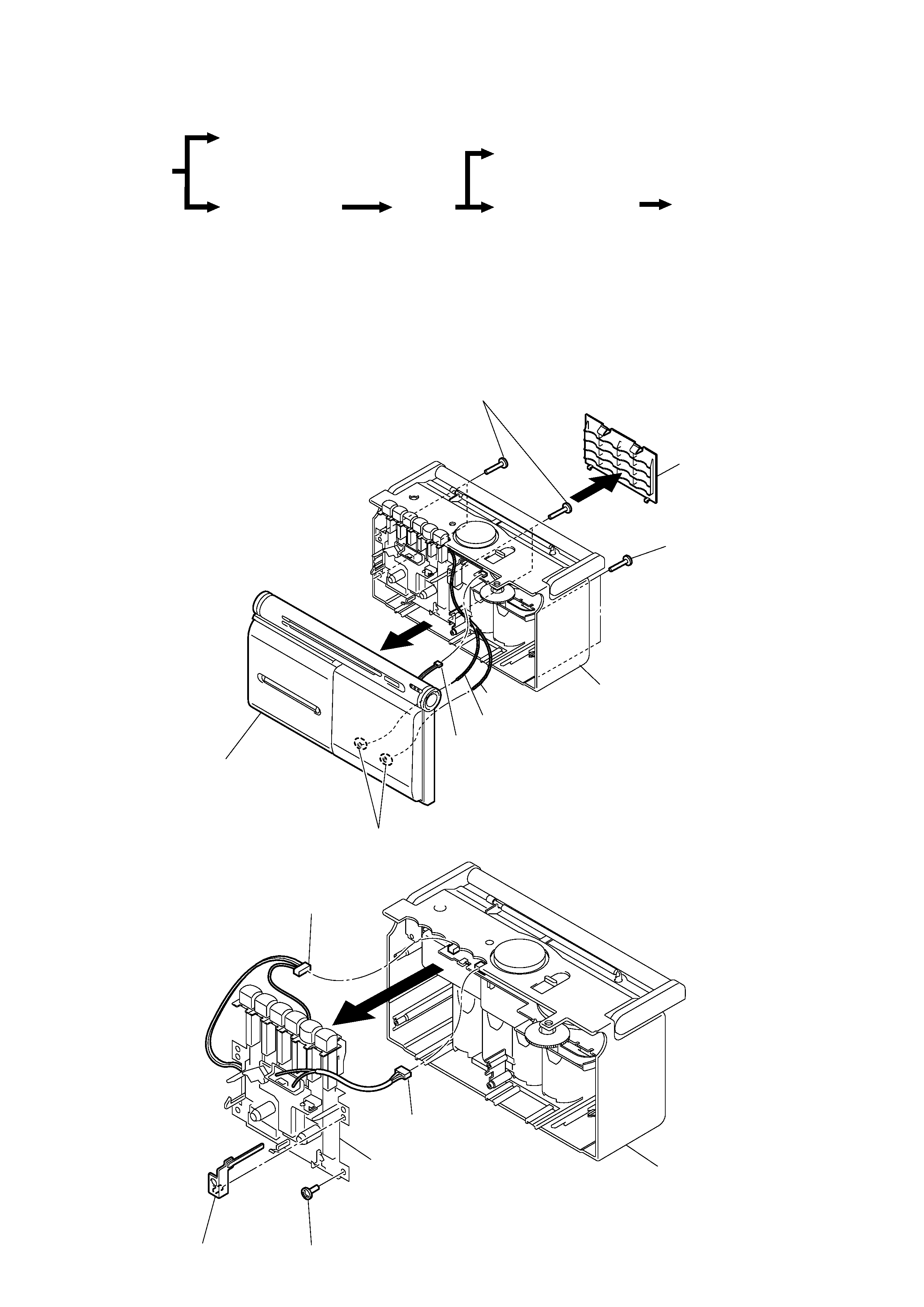
Note : Follow the disassembly procedure in the numerical order given.
2-2. MD ASSY
· The equipment can be removed using the following procedure.
Set
Cabinet (front) sub ASSY
Cabinet (rear) ASSY
Jack board, Main board
Batt(+) board, Power board
MD ASSY
Record/playback head (HRP101),
Reel/capstan motor (M101), Belt
3
1
2Screws (+ BVTP 3X14)
2Screws
(+ BVTP 3X14)
4Remove solder (two place)
5CNP103
6
Cabinet (front) sub ASSY
Lid, BATT
Cabinet (rear) ASSY
White
White/red
3
4
CNP102
1Screw (+ BVTP 3X10)
2CNP101
5
MD ASSY
Bracket (VOL)
Cabinet (rear) ASSY
· Abbreviation
SP
: Singapore
AR
:Argentina
HK
: Hong Kong
MX
:Mexican
IT
: Italian
TW
:Taiwan
C&SA : Central and South America
CET
: East European & Russian
2-1. CABINET (FRONT) SUB ASSY, CABINET (REAR) ASSY
4
CFM-20
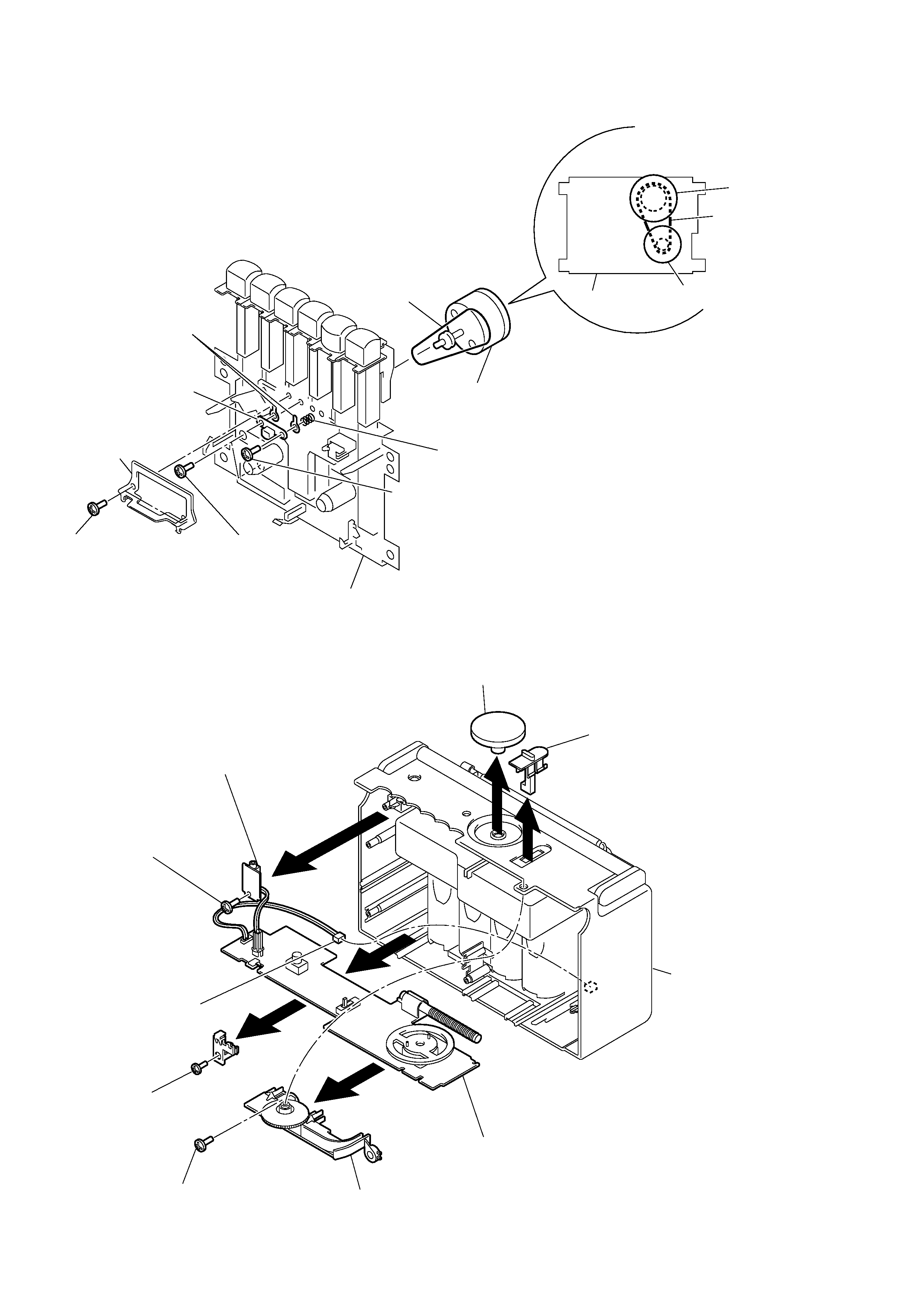
2-3. RECORD/PLAYBACK HEAD (HRP101), REEL/CAPSTAN MOTOR (M101), BELT
2-4. JACK BOARD (AEP, UK, IT, CET, HK, SP, AR model), MAIN BOARD
1Screws Tapping+B
(+PTT 2X5(s))
MD ASSY
4
Record/playback
head (HRP101)
8
Reel/capstan
motor (M101)
MD ASSY
M101
Belt
Flywheel ASSY
· Attaching belt
6
Spring, Compr
3Screws
+ PTT 2X 5
7Screws + P2.6X 5
9
Belt
5Lug (T), plate
2
Guide, tape
7
8
6
1
2
0
4
Screw
(+ BVTP 3X10)
3Screw
(+ BVTP 3X10)
Jack board
9
CNP901
Main board
MCabinet (rear)
knob (VOL)
knob (FUN)
Chasis
5
Screw
(+ BVTP 3X10)
5
CFM-20
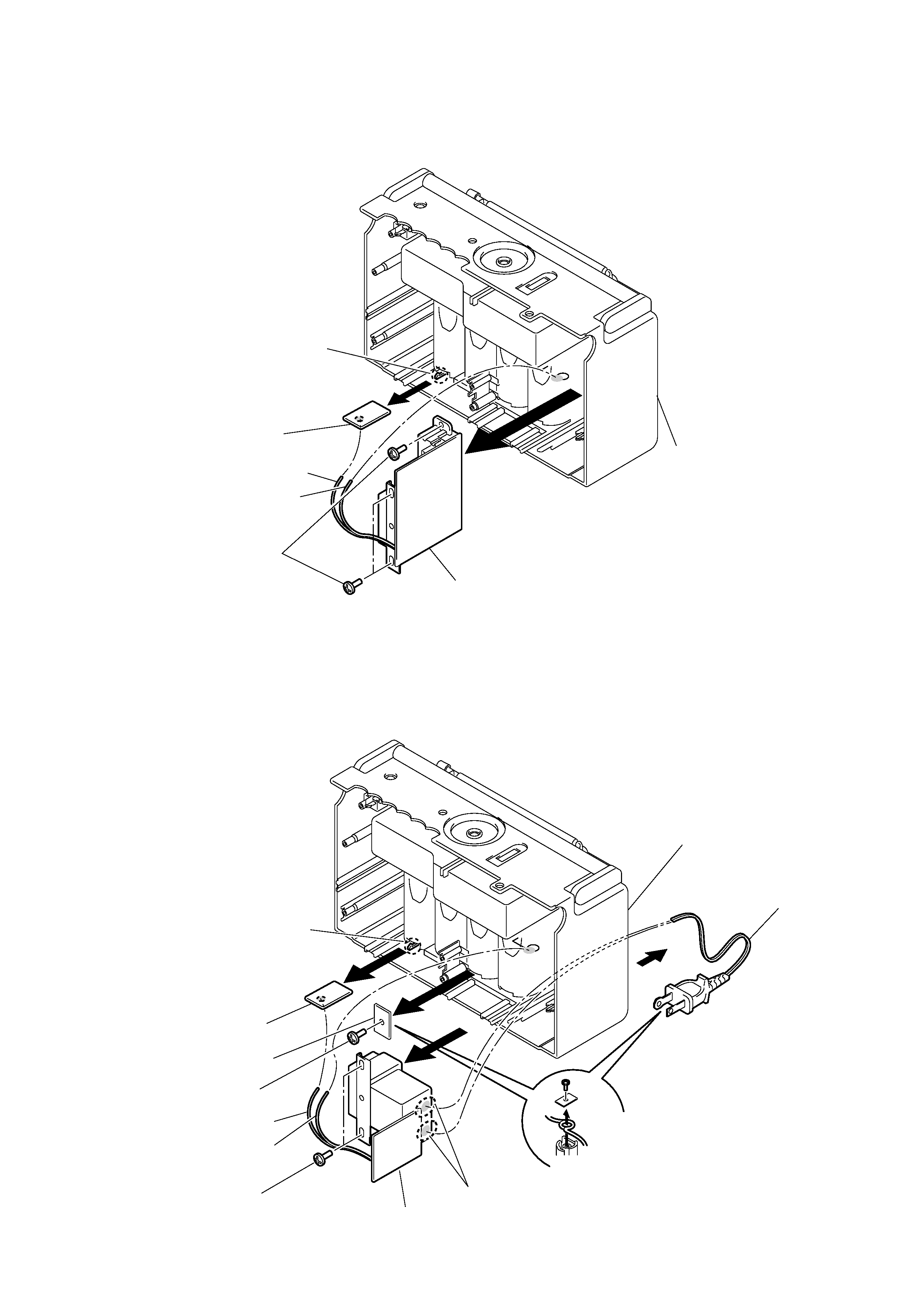
2-5. BATT (+) BOARD, POWER BOARD
(AEP, UK, IT, CET, HK, SP, AR model)
2-6. BATT (+) BOARD, POWER BOARD
(C&SA, MX, TW model)
Note on attaching power cord
On attaching power cord, first,
turn it around the projection on
"Cabi, rear" as shown in the
figure and secure it with "PWB,
cord retainer".
2
4
6
8
3Screw
(+ BVTP 3X10)
1Claw
Power board
Cord, power
Batt (+) board
PWB, Cord retainer
White
Red
5
7
Screws
(+ BVTP 3X10)
Remove solder
(two places)
Cabinet (rear)
1
2
4
Claw
3Screws
(+ BVTP 3X10)
Power board
Batt (+) board
Red
White
Cabinet (rear)