SERVICE MANUAL
US Model
E Model
SPECIFICATIONS
CFD-S28
CD
Model Name Using Similar Mechanism
NEW
Section
CD Mechanism Type
KSM-213CDM
Optical Pick-up Name
KSS-213C
TAPE
Model Name Using Similar Mechanism
CFD-V10
Section
Tape Transport Mechanism Type
MF-V10-117
Continued on next page
CD RADIO CASSETTE-CORDER
Ver. 1.1 2005.09
9-926-984-12
2005I05-1
© 2005.09
Sony Corporation
Personal Audio Group
Published by Sony Engineering Corporation
2
TABLE OF CONTENTS
1.
SERVICING NOTES ............................................... 3
2.
GENERAL ................................................................... 4
3.
DISASSEMBLY ......................................................... 7
4.
MECHANICAL ADJUSTMENTS ....................... 13
5.
ELECTRICAL ADJUSTMENTS
TAPE DECK Section ...................................................... 13
TUNER Section .............................................................. 14
CD Section ...................................................................... 16
6.
DIAGRAMS
6-1. Block Diagram CD Section ...................................... 17
6-2. Block Diagram TUNER Section .............................. 19
6-3. Block Diagram MAIN Section ................................. 21
6-4. Printed Wiring Board TUNER Section ................... 26
6-5. Schematic Diagram TUNER Section ....................... 27
6-6. Printed Wiring Boards MAIN Section .................... 29
6-7. Schematic Diagram MAIN Section (1/3) ................ 32
6-8. Schematic Diagram MAIN Section (2/3) ................ 35
6-9. Schematic Diagram MAIN Section (3/3) ................ 37
6-10. Printed Wiring Boards
POWER SUPPLY Section ........................................ 41
6-11. Schematic Diagram POWER SUPPLY Section ...... 43
6-12. IC Pin Function Description ........................................... 49
7.
EXPLODED VIEWS ................................................ 51
8.
ELECTRICAL PARTS LIST ............................... 57
SAFETY-RELATED COMPONENT WARNING!!
COMPONENTS IDENTIFIED BY MARK
! OR DOTTED
LINE WITH MARK
! ON THE SCHEMATIC DIAGRAMS
AND IN THE PARTS LIST ARE CRITICAL TO SAFE
OPERATION. REPLACE THESE COMPONENTS WITH
SONY PARTS WHOSE PART NUMBERS APPEAR AS
SHOWN IN THIS MANUAL OR IN SUPPLEMENTS PUB-
LISHED BY SONY.
Flexible Circuit Board Repairing
· Keep the temperature of the soldering iron around 270 °C dur-
ing repairing.
· Do not touch the soldering iron on the same conductor of the
circuit board (within 3 times).
· Be careful not to apply force on the conductor when soldering
or unsoldering.
Notes on chip component replacement
· Never reuse a disconnected chip component.
· Notice that the minus side of a tantalum capacitor may be dam-
aged by heat.
CAUTION
Use of controls or adjustments or performance of procedures
other than those specified herein may result in hazardous ra-
diation exposure.
This appliance is classified as a CLASS 1 LASER product.
The CLASS 1 LASER PRODUCT MARKING is located on
the rear exterior.
Laser component in this product is capable of emitting radiation
exceeding the limit for Class 1.
3
SECTION 1
SERVICENG NOTES
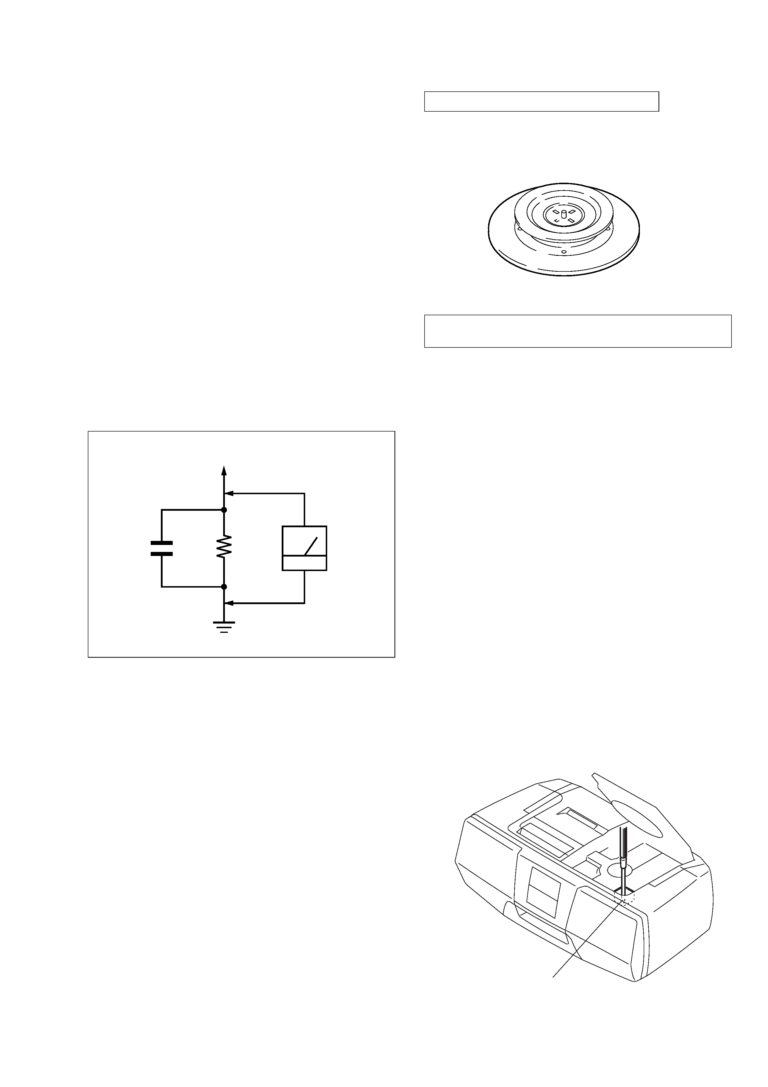
CHUCK PLATE JIG ON REPAIRING
On repairing CD section, playing a disc without the lid (CD), use
Chuck Plate Jig.
· Code number of Chuck Plate Jig: X-4918-255-1
The laser diode in the optical pick-up block may suffer electro-
static break-down because of the potential difference generated
by the charged electrostatic load, etc. on clothing and the human
body.
During repair, pay attention to electrostatic break-down and also
use the procedure in the printed matter which is included in the
repair parts.
The flexible board is easily damaged and should be handled with
care.
NOTES ON LASER DIODE EMISSION CHECK
The laser beam on this model is concentrated so as to be focused
on the disc reflective surface by the objective lens in the optical
pick-up block. Therefore, when checking the laser diode emis-
sion, observe from more than 30 cm away from the objective lens.
LASER DIODE AND FOCUS SEARCH OPERATION
CHECK
1. Turn ON the POWER button and press FUNCTION button to
CD position.
2. Open the lid (CD).
3. Turn on S501 with screwdriver, etc. as following figure.
4. Press the CD
fl button.
5. Confirm the laser diode emission while observing the object-
ing lens. When there is no emission, Auto Power Control cir-
cuit or Optical Pick-up is broken.
Objective lens moves up and down three times for focus search.
NOTES ON HANDLING THE OPTICAL PICK-UP
BLOCK OR BASE UNIT
S501
SAFETY CHECK-OUT
After correcting the original service problem, perform the follow-
ing safety check before releasing the set to the customer:
Check the antenna terminals, metal trim, "metallized" knobs,
screws, and all other exposed metal parts for AC leakage.
Check leakage as described below.
LEAKAGE TEST
The AC leakage from any exposed metal part to earth ground and
from all exposed metal parts to any exposed metal part having a
return to chassis, must not exceed 0.5 mA (500 microampers.).
Leakage current can be measured by any one of three methods.
1. A commercial leakage tester, such as the Simpson 229 or RCA
WT-540A. Follow the manufacturers' instructions to use these
instruments.
2. A battery-operated AC milliammeter. The Data Precision 245
digital multimeter is suitable for this job.
3. Measuring the voltage drop across a resistor by means of a
VOM or battery-operated AC voltmeter. The "limit" indica-
tion is 0.75 V, so analog meters must have an accurate low-
voltage scale. The Simpson 250 and Sanwa SH-63Trd are ex-
amples of a passive VOM that is suitable. Nearly all battery
operated digital multimeters that have a 2 V AC range are suit-
able. (See Fig. A)
Fig. A.
Using an AC voltmeter to check AC leakage.
1.5 k
0.15
µF
AC
voltmeter
(0.75 V)
To Exposed Metal
Parts on Set
Earth Ground
4
SECTION 2
GENERAL
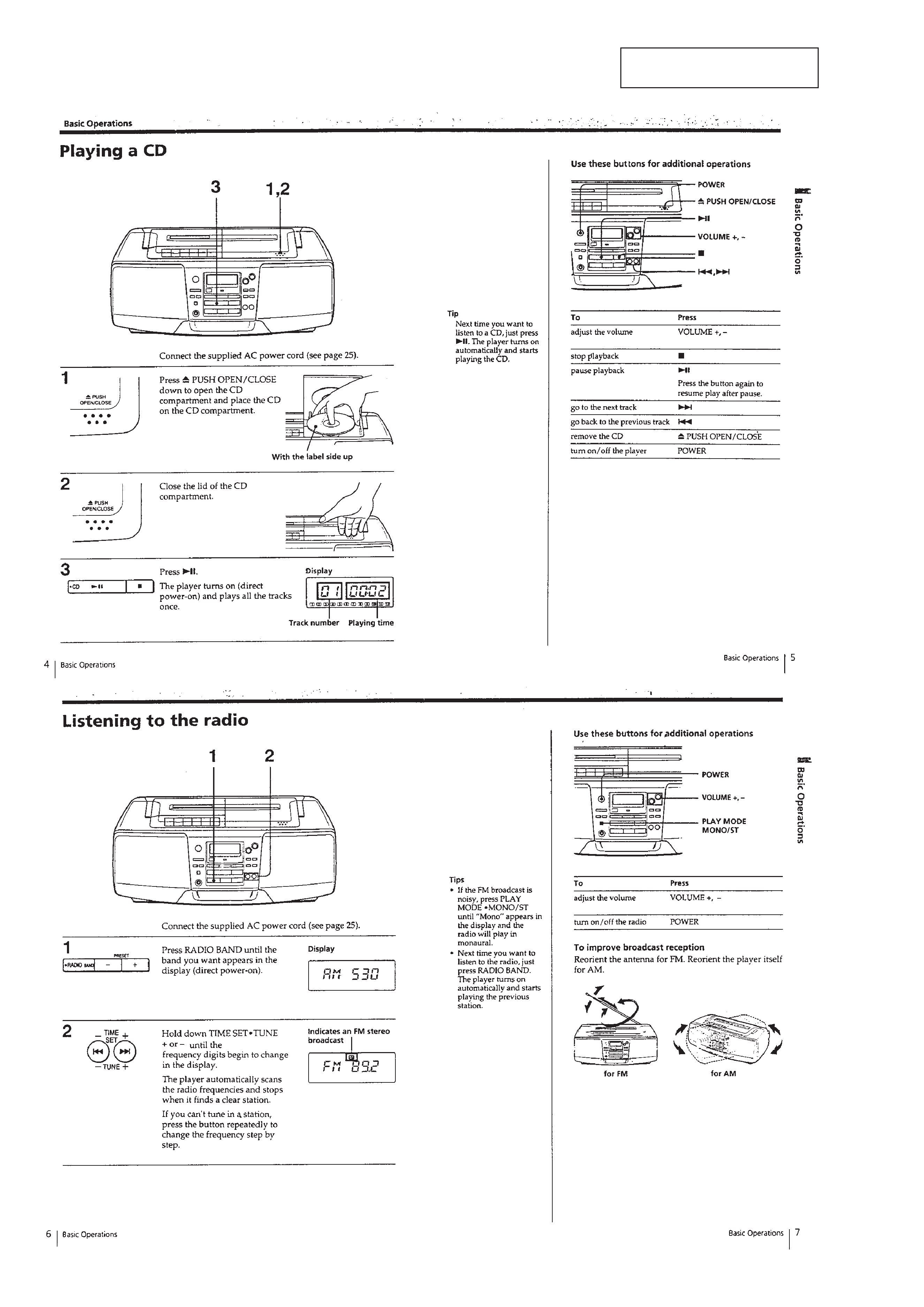
This section is extracted from
instruction manual.
5