1
SERVICE MANUAL
CFD-S20CP
CD RADIO CASSETTE-CORDER
Other Specifications
CD player section
System
Compact disc digital audio system
Laser diode properties
Material: GaAlAs
Wave length: 780 nm
Emission duration: Continuous
Laser output: Less than 44.6
µW
(This output is the value measured at a distance of
about 200 mm from the objective lens surface on
the optical pick-up block with 7 mm aperture.)
Spindle speed
200 r/min (rpm) to 500 r/min (rpm) (CLV)
Number of channels
2
Frequency response
20 - 20,000 Hz +1/2 dB
Wow and flutter
Below measurable limit
SPECIFICATIONS
Continued on next page
Radio section
Frequency range
FM: 87.5 - 108 MHz
AM: 530 - 1,710 kHz (US, CND)
AM: 531 - 1,611 kHz (KR, TW)
Antennas
FM: Telescopic antenna
AM: Built-in ferrite bar antenna
Cassette-corder section
Recording system
4-track 2 channel stereo
Fast winding time
Approx. 120 sec. with Sony cassette C-60
Frequency response
TYPE I (normal): 80 - 10,000 Hz
Ver 1.4 2004. 09
9-873-978-05
2004I04-1
© 2004. 09
AUDIO POWER SPECIFICATIONS
POWER OUTPUT AND TOTAL
HARMONIC DISTORTION
With 3.2-ohm loads, both channels driven from
150 - 6,300 Hz; rated 1.8 W per channel-
minimum RMS power, with no more than 10%
total harmonic distortion in AC operation.
Sony Corporation
Personal Audio Company
Published by Sony Engineering Corporation
US Model
Canadian Model
Taiwan Model
Korean Model
CD
Model Name Using Similar Mechanism CFD-S400/S500
Section
CD Mechanism Type
KSM-213RDP
Optical Pick-up Name
KSS-213R
TC
Model Name Using Similar Mechanism CFD-S400/S500
Section Tape Transport Mechanism Type
MF-S200

2
General
Speaker
Full range: 10 cm (4 in.) dia.,
3.2 ohms, cone type (2)
Outputs
Headphones jack (stereo minijack)
For 16 - 68 ohms impedance headphones
Power output
2.3 W + 2.3 W (at 3.2 ohms, 10%
harmonic distortion)
Power requirements
For CD radio cassette-corder:
US, CND, TW model:
120 V AC, 60 Hz
KR model:
220 V AC, 60 Hz
9 V DC, 6 size D (R20) batteries
For remote control:
3 V DC, 2 size AA (R6) batteries
Battery life
For CD radio cassette-corder:
FM recording
Sony R20P: approx. 13.5 h
Sony alkaline LR20: approx. 20 h
Tape playback
Sony R20P: approx. 7.5 h
Sony alkaline LR20: approx. 15 h
CD playback
Sony R20P: approx. 2.5 h
Sony alkaline LR20: approx. 7 h
Dimensions
Approx. 386
× 166 × 252 mm (w/h/d)
(15 1/4
× 6 5/8 × 10 inches) (incl. projecting parts)
Mass
Approx. 3.3 kg (7 lb. 4 oz.) (incl. batteries)
Supplied accessories
AC power cord (1)
Remote control (RMT-CS20CPA) (1)
Design and specifications are subject to change without
notice.
CFD-S20CP
SAFETY-RELATED COMPONENT WARNING!!
COMPONENTS IDENTIFIED BY MARK 0 OR DOTTED LINE
WITH MARK 0 ON THE SCHEMATIC DIAGRAMS AND IN
THE PARTS LIST ARE CRITICAL TO SAFE OPERATION.
REPLACE THESE COMPONENTS WITH SONY PARTS WHOSE
PART NUMBERS APPEAR AS SHOWN IN THIS MANUAL OR
IN SUPPLEMENTS PUBLISHED BY SONY.
CAUTION
Use of controls or adjustments or performance of proce-
dures other than those specified herein may result in haz-
ardous radiation exposure.
Flexible Circuit Board Repairing
· Keep the temperature of the soldering iron around 270°C during
repairing.
· Do not touch the soldering iron on the same conductor of the
circuit board (within 3 times).
· Be careful not to apply force on the conductor when soldering
or unsoldering.
Notes on Chip Component Replacement
· Never reuse a disconnected chip component.
· Notice that the minus side of a tantalum capacitor may be dam-
aged by heat.
NOTES ON HANDLING THE OPTICAL PICK-UP BLOCK
OR BASE UNIT
The laser diode in the optical pick-up block may suffer electrostatic
breakdown because of the potential difference generated by the
charged electrostatic load, etc. on clothing and the human body.
During repair, pay attention to electrostatic breakdown and also use
the procedure in the printed matter which is included in the repair
parts.
The flexible board is easily damaged and should be handled with
care.
NOTES ON LASER DIODE EMISSION CHECK
The laser beam on this model is concentrated so as to be focused on
the disc reflective surface by the objective lens in the optical pick-
up block. Therefore, when checking the laser diode emission,
observe from more than 30 cm away from the objective lens.
ATTENTION AU COMPOSANT AYANT RAPPORT
À LA SÉCURITÉ!!
LES COMPOSANTS IDENTIFIÉS PAR UNE MARQUE 0 SUR LES
DIAGRAMMES SCHÉMATIQUES ET LA LISTE DES PIÈCES SONT
CRITIQUES POUR LA SÉCURITÉ DE FONCTIONNEMENT. NE
REMPLACER CES COMPOSANTS QUE PAR DES PIÈCES SONY
DONT LES NUMÉROS SONT DONNÉS DANS CE MANUEL OU
DANS LES SUPPLÉMENTS PUBLIÉS PAR SONY.
·Abbreviation
CND
: Canadian model
KR
: Korean model
TW
: Taiwan model
Ver 1.3

3
TABLE OF CONTENTS
1. SERVICING NOTES ......................................................... 4
2. GENERAL ............................................................................ 5
3. DISASSEMBLY
3-1. Cabinet Top Assy ................................................................ 7
3-2. Cabinet Front Assy, Cabinet Rear Assy .............................. 7
3-3. Wires ................................................................................... 8
3-4. MD Block ............................................................................ 8
3-5. Cassette Door Assy ............................................................. 9
3-6. LCD Board, Control (4) Board ........................................... 9
3-7. Main Board ....................................................................... 10
3-8. Tuner Board ....................................................................... 10
3-9. Power Board ...................................................................... 11
3-10. CD Lid ............................................................................... 11
3-11. CD Block Assy .................................................................. 12
3-12. Optical Pick-up ................................................................. 12
3-13. R/P Head (HRP301), TC Board ........................................ 13
3-14. Motor Assy (M801), Main Belt (B), Sub Belt (B) ............ 13
4. MECHANICAL ADJUSTMENTS ............................... 14
5. ELECTRICAL ADJUSTMENTS
Tape Section .......................................................................... 14
Tuner Section ......................................................................... 15
CD Section ............................................................................ 16
6. DIAGRAMS
6-1. IC Pin Descriptions ........................................................... 17
6-2. Circuit Boards Location .................................................... 19
6-3. Block Diagram CD Section ......................................... 20
6-4. Block Diagram Main Section ...................................... 21
6-5. Printed Wiring Board CD Section ............................... 22
6-6. Schematic Diagram CD Section .................................. 24
6-7. Printed Wiring Board Tuner Section ........................... 25
6-8. Schematic Diagram Tuner Section .............................. 26
6-9. Printed Wiring Boards Main Section .......................... 27
6-10. Schematic Diagram Main Section (1/2) ...................... 28
6-11. Schematic Diagram Main Section (2/2) ...................... 29
6-12. Printed Wiring Board TC Section ............................... 30
6-13. Schematic Diagram TC Section .................................. 31
6-14. Printed Wiring Boards Control Section ....................... 32
6-15. Schematic Diagram Control Section ........................... 33
6-16. Printed Wiring Boards Display Section ...................... 34
6-17. Schematic Diagram Display Section ........................... 35
6-18. Printed Wiring Boards Power Supply Section ............ 36
6-19. Schematic Diagram Power Supply Section ................. 37
6-20. IC Block Diagrams ............................................................ 38
7. EXPLODED VIEWS
7-1. Main Section ..................................................................... 40
7-2. Cabinet Front Section ........................................................ 41
7-3. Cabinet Top Section .......................................................... 42
7-4. Cabinet Rear Section ......................................................... 43
7-5. Tape Mechanism Section .................................................. 44
7-6. CD Mechanism Section .................................................... 45
8. ELECTRICAL PARTS LIST ......................................... 46
CFD-S20CP
4
CFD-S20CP
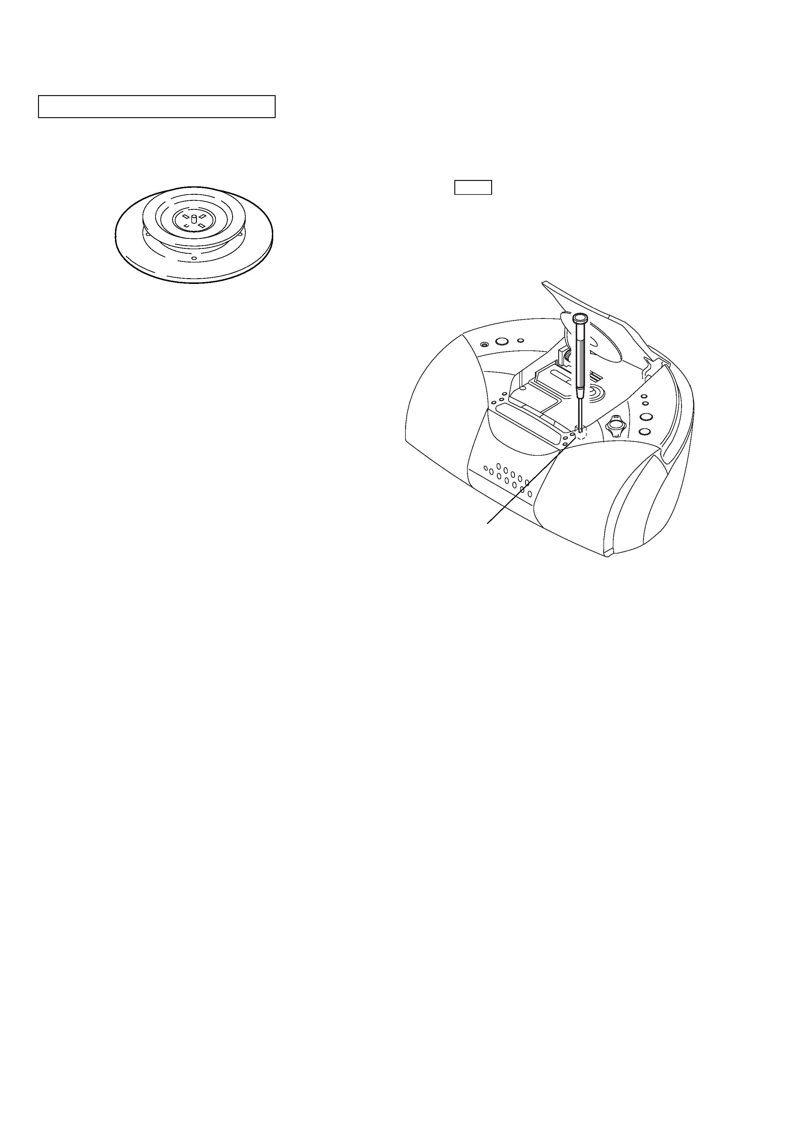
CHUCK PLATE JIG ON REPAIRING
On repairing CD section, playing a disc without the lid (CD), use
Chuck Plate Jig.
· Code number of Chuck Plate Jig: X-4918-255-1
SECTION 1
SERVICING NOTES
LASER DIODE AND FOCUS SEARCH OPERATION
CHECK
1. Turn ON the [POWER] button and press [CD] button to
CD position.
2. Open the CD lid.
3. Turn on S801 with screwdriver, etc. as following figure.
4. Press the N X (CD) button.
5. Confirm the laser diode emission while observing the objecting
lens. When there is no emission, Auto Power Control circuit or
Optical Pick-up is broken.
Objective lens moves up and down three times for focus search.
S801
5
CFD-S20CP
SECTION 2
GENERAL
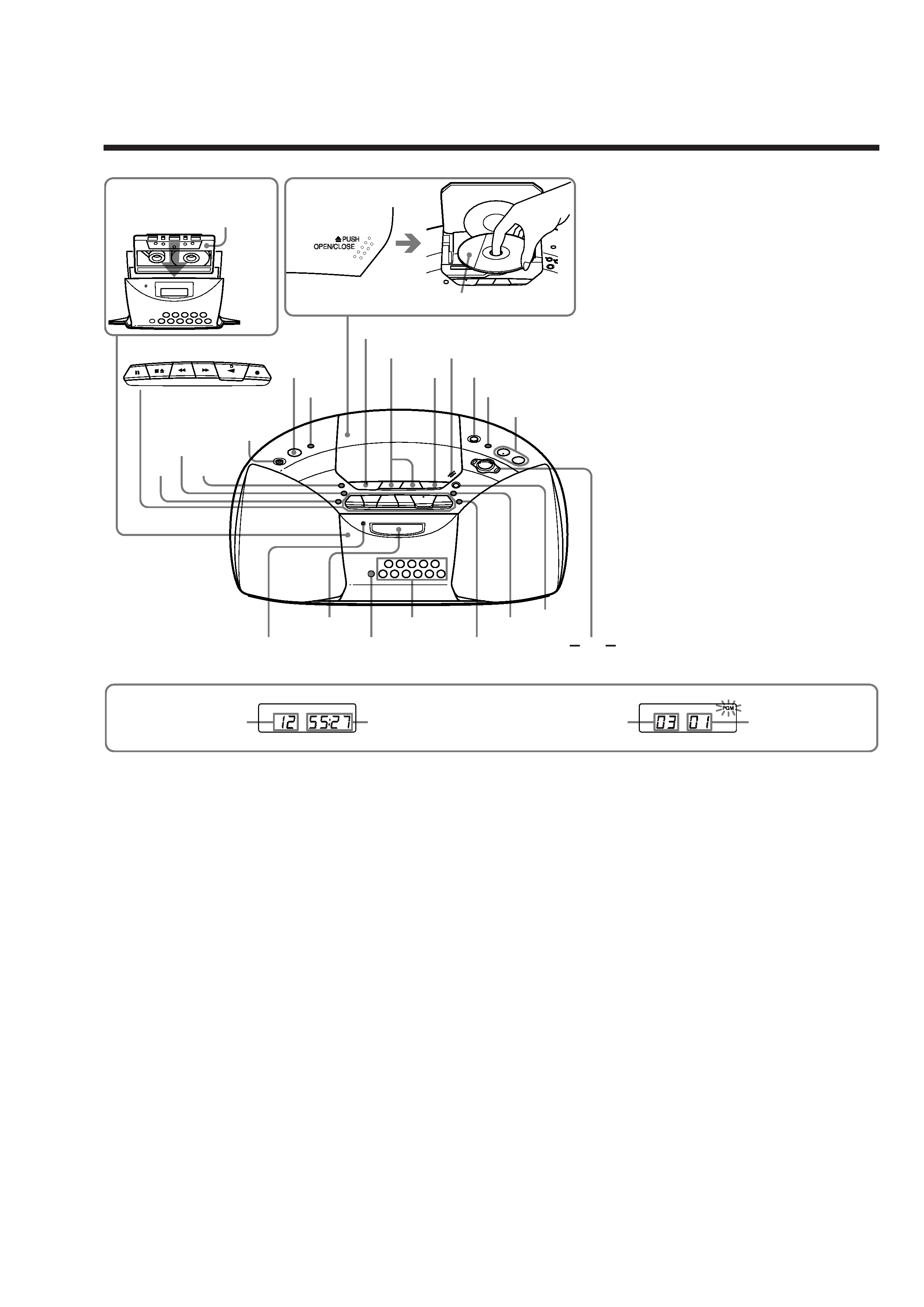
Location of controls
Loading a CD
With the labeled side up
Inserting a cassette
With the side you want
to play facing you
Total track number
Programmed track
Playing order
Total playing time
Display
CD
MEGA BASS
Z PUSH
OPEN/CLOSE
VOL +*,
., >
TUNE , +
DISPLAY
ENT
MEMORY
MODE
REPEAT
i
Number buttons
x
u*
POWER
SLEEP
OPR/BATT
RADIO BAND
AUTO PRESET
TAPE
Display
Remote sensor
MP3
FOLDER
FOLDER +
SOUND
*The button has a tactile dot.
*