MICROFILM
SERVICE MANUAL
General
Spread method
Direct-Sequence Spread-Spectrum
Access method
FDMA-TDD
Frequency band
902 - 928 MHz
Operating channel
20 channels
Dial signal
Tone, 10 PPS (pulse) selectable
Supplied accessories
AC power adaptor (AC-T46)
Telephone line cords (2)
Wall bracket/stand for base unit
Rechargeable battery pack (BT-T24)
Handset
Power source
Rechargeable battery pack BP-T24
Battery life
Standby: Approx. 10 days (RING ON
mode)
Approx. 1 month (RING OFF
mode)
Talk:
Approx. 6 hours
Dimensions
Approx. 2 3/8 x 7 x 1 13/16 inches (w/h/d),
antenna excluded
(approx. 58 x 177 x 46 mm)
Antenna: 2 7/8 inches (72 mm)
Mass
Approx. 9 oz (approx. 260 g), battery
included
Base unit
Power source
DC 9V from AC power adaptor AC-T46
Battery charging time
Approx. 12 hours
Dimensions
Approx. 6 3/4 x 2 3/8 x 8 1/2 inches (w/h/d),
antenna excluded
(approx. 170 x 60 x 214 mm)
Antenna: 6 1/ 2 inches (165 mm)
Mass
Approx. 18 oz (approx. 520 g), wall bracket
excluded
Answering machine
Maximum recording time
About 20 minutes, using incorporated IC
Greeting message
Up to 4 minutes
Incoming message
Up to 4 minutes/message
Memo
Up to 4 minutes/message
Design and specifications are subject to
change without notice.
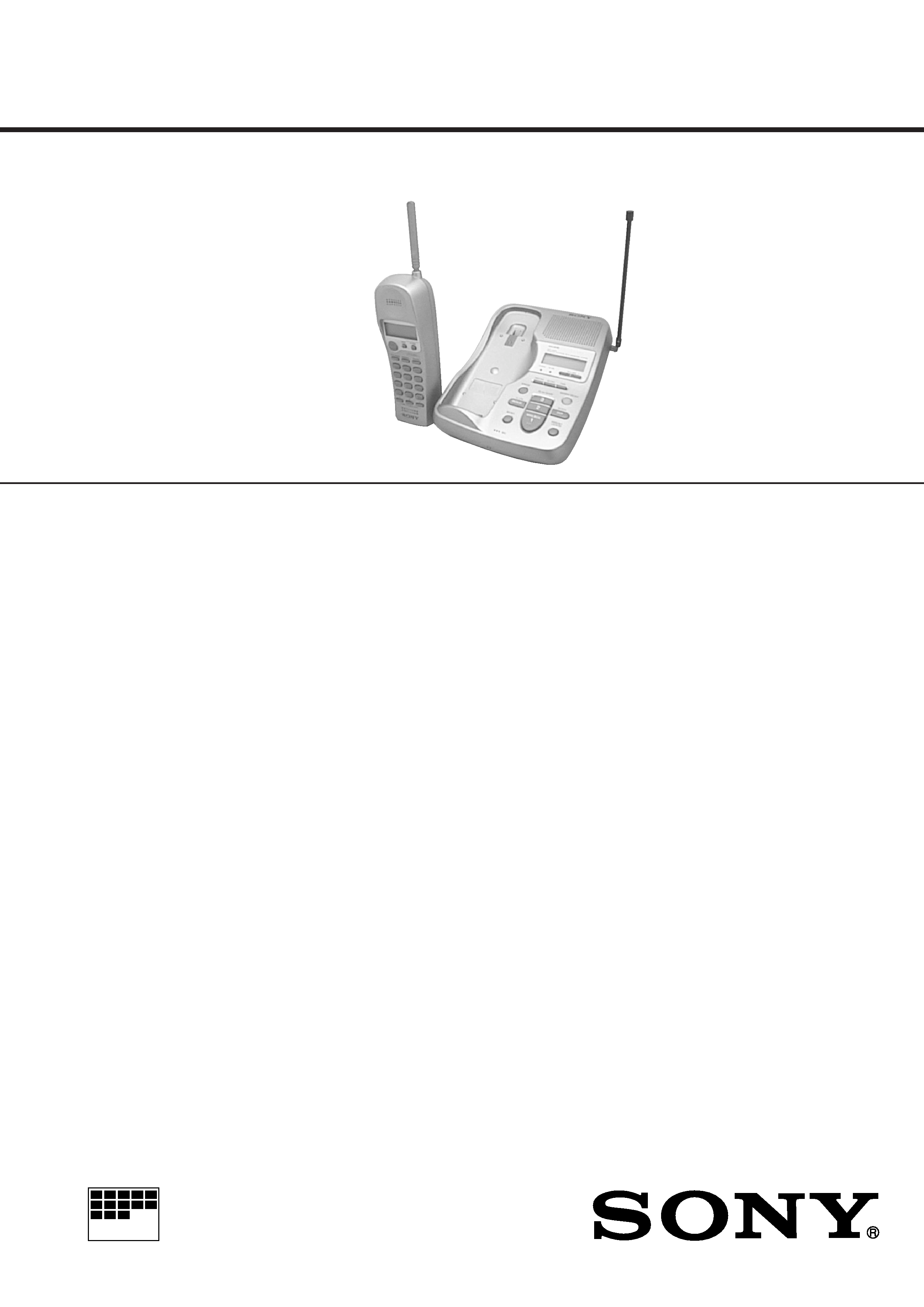
CORDLESS TELEPHONE
WITH ANSWERING SYSTEM
US Model
Canadian Model
SPECIFICATIONS
SPP-A968

2
TABLE OF CONTENTS
1.
GENERAL
Identifying the Parts ........................................................
3
Setting Up the Base Unit ................................................
4
Preparing the Battery Pack .............................................
4
Entering Your Area Code ................................................
5
Making Calls ...................................................................
5
Receiving Calls ...............................................................
6
One-touch Dialing ...........................................................
6
Phone Directory ..............................................................
7
Paging ..............................................................................
8
Preparing the Answering Machine .................................
8
Playing Back Messages ..................................................
9
Screening Incoming Calls ............................................... 10
Recording a Memo .......................................................... 10
Operating from an Outside Phone .................................. 10
Understanding the Caller ID Service .............................. 11
Looking at the Caller ID List .......................................... 11
Using the Caller ID List .................................................. 12
Using "Caller ID with Call Waiting" Service ................ 12
2.
DISASSEMBLY ......................................................... 13
3.
900 MHz SYSTEM OPERATION ........................ 15
4.
TEST MODE ............................................................... 18
5.
ELECTRICAL ADJUSTMENTS
5-1. Base Unit ......................................................................... 25
5-2. Handset ............................................................................ 27
6.
DIAGRAMS
6-1. Block Diagram BASE UNIT Section (1/2) ............. 28
6-2. Block Diagram BASE UNIT Section (2/2) ............. 29
6-3. Block Diagram HANDSET Section ........................ 30
6-4. Note for Printed Wiring Boards and
Schematic Diagrams ....................................................... 31
6-5. Schematic Diagram BASE MAIN Board (1/3) ....... 32
6-6. Schematic Diagram BASE MAIN Board (2/3),
BASE MICROPHONE Board ..................................... 33
6-7. Schematic Diagram BASE MAIN Board (3/3) ....... 34
6-8. Printed Wiring Boards BASE MAIN/
BASE MICROPHONE Boards .................................... 35
6-9. Printed Wiring Board DSP Board ............................ 36
6-10. Schematic Diagram DSP Board .............................. 37
6-11. Printed Wiring Board BASE KEY Board ............... 38
6-12. Schematic Diagram BASE KEY Board .................. 39
6-13. Printed Wiring Board HAND MAIN Board ........... 40
6-14. Schematic Diagram HAND MAIN Board .............. 41
6-15. IC Pin Function Description ........................................... 44
7.
EXPLODED VIEWS ................................................ 52
8.
ELECTRICAL PARTS LIST ............................... 54
Notes on chip component replacement
· Never reuse a disconnected chip component.
· Notice that the minus side of a tantalum capacitor may be dam-
aged by heat.
ATTENTION AU COMPOSANT AYANT RAPPORT
À LA SÉCURITÉ!
LES COMPOSANTS IDENTIFIÉS PAR UNE MARQUE 0
SUR LES DIAGRAMMES SCHÉMATIQUES ET LA LISTE
DES PIÈCES SONT CRITIQUES POUR LA SÉCURITÉ
DE FONCTIONNEMENT. NE REMPLACER CES COM-
POSANTS QUE PAR DES PIÈCES SONY DONT LES
NUMÉROS SONT DONNÉS DANS CE MANUEL OU
DANS LES SUPPLÉMENTS PUBLIÉS PAR SONY.
SAFETY-RELATED COMPONENT WARNING!!
COMPONENTS IDENTIFIED BY MARK 0 OR DOTTED
LINE WITH MARK 0 ON THE SCHEMATIC DIAGRAMS
AND IN THE PARTS LIST ARE CRITICAL TO SAFE
OPERATION. REPLACE THESE COMPONENTS WITH
SONY PARTS WHOSE PART NUMBERS APPEAR AS
SHOWN IN THIS MANUAL OR IN SUPPLEMENTS PUB-
LISHED BY SONY.
3
SECTION 1
GENERAL
Getting Started
14
US
Identifying the parts
1
Display window (p.9, 34)
2
IN USE lamp
Lights when the cordless handset is
in use.
3
CHARGE lamp (p. 11)
Lights while the battery is being
charged.
4
GREETING button (p. 29)
Plays back the greeting message.
Also used when recording a
greeting.
5
ERASE button (p. 30, 34)
Erases the recorded greeting or
messages.
6
REPEAT/SLOW button (p. 28,
34)
Press to repeat the current message
or go back to the previous message.
Keep the button pressed for slow
playback of messages.
7
MEMO button (p. 36)
Records a memo message.
8
MIC (microphone) (p. 29, 36)
9
Antenna (p. 9, 47)
0
Speaker
qa
VOLUME +/ buttons (p. 34)
Adjusts the speaker volume.
qs
TIME button (p. 28)
Press when setting the day andtime,
or to check the current time.
qd
SET/REC button (p. 28, 29, 37)
Press to set the time or to record a
greeting. Also used when setting
the remote ID code (security code).
qf
Wall bracket/stand for base
unit (p. 9, 47)
qg
ANSWER ON/OFF button
(p. 33)
Turns the answering function on or
off. Lights when the answering
function is on, and flashes when a
new message is recorded. Also used
when setting the remote ID code
(security code).
qh
SKIP/QUICK button (p. 28, 34)
Press to skip to the next message.
Keep the button pressed for quick
playback of messages.
Refer to the pages indicated in parentheses for details.
1
2
3
4
5
6
7
8
9
0
qa
qs
qd
qf
qg
qh
qj
qk
Base Unit
Getting
Started
Getting Started
15
US
1
Memory capacity indicator
(p. 32)
Indicates the available memory
capacity, from E (Empty) to F (Full),
for recording. The bars increase as
the available memory capacity
decreases.
2
MAILBOX indicator (p. 34)
Displayed when there are messages
recorded and when the messages
are being played back.
Flashes when there are new
messages recorded.
3
Message number indicator
(p. 34)
Indicates the number of new
messages recorded. "A" appears in
the announcement only mode. "F"
appears when there is no space to
record messages. "P" appears when
the power is turned on.
4
VOL (volume) indicator
Indicates the speaker volume. The
bars increase as the volume is
turned up.
qj
HANDSET LOCATOR button
(p. 27)
Allows you to page the cordless
handset.
qk
PLAY/STOP (MAILBOX 1, 2, 3)
buttons (p. 34)
Plays back the messages in each
mail box.
ql
AUDIBLE INDICATE switch
(p. 32)
Selects the answering mode.
w;
RINGER SELECT switch (p. 31)
Selects the ring time.
wa
DIAL MODE switch (p. 10)
Selects pulse or tone dialing.
ws
Hook for AC power adaptor
cord (p. 9)
wd
DC IN 9V jack (p. 9)
wf
LINE (telephone line) jack
(p. 9)
continued
ql
w;
wf
wd
ws
wa
12
3
4
Display
The display on the base unit shows the
answering machine operation.
Getting Started
16
US
Handset
1
Antenna
2
Speaker
3
Jog dial (p. 13, 23, 40)
4
TALK button (p. 17, 35)
Lets you make or receive a call.
5
REDIAL button (p. 18)
Redials the last number called.
6
VOL (volume) /PGM (program)
button (p. 13, 17, 21, 23)
Used to adjust the speaker volume.
Also used to store numbers in
Phone Directory or for one-touch
dialing.
7
TONE button (p. 17, 38)
Allows you to switch temporarily to
tone dialing.
8
Battery compartment (p. 11)
9
RING switch (p. 12, 20)
Switches the ringing mode.
q;
Display window (p. 39)
qa
CALL WAITING/FLASH button
(p. 19, 46)
Switches to a second call if you
have "call waiting" service, or lets
you make a new call.
qs
OFF button (p. 17)
Allows you to disconnect the call.
qd
PAUSE button (p. 22)
Inserts a pause in the dialing
sequence.
qf
Dialing keys (p. 17)
qg
ONE-TOUCH DIAL (A, B, C)
buttons (p. 21)
qh
Microphone
1
7
8
9
0
qa
qs
qd
qf
qg
qh
6
5
4
3
2
Identifying the parts (continued)
This section is extracted from
instruction manual.
4
Getting Started
8
US
Step 2
Away from television
sets and other
electronic equipment
Away from a microwave
oven
Away from excessive
moisture, extremely low
temperatures, dust,
mechanical vibration, or
shock
Away from a personal
computer
Away from another
cordless telephone
Near a central location
and on a level surface
Away from heat sources, such as radiators,
airducts, and sunlight
Away from noise sources such as a window
by a street with heavy traffic
CAUTION: · Should you experience intermittent loss of audio during a conversation, try
moving closer to the base unit or move the base unit from other noise sources.
· The cordless telephone operates at a frequency that may cause interference to
nearby TVs and VCRs; the base unit should not be placed near or on the top of a
TV or VCR; and, if interference is experienced, moving the cordless telephone
farther away from the TV or VCR will often reduce or eliminate the interference.
Setting up the base unit
Do the following steps:
· Choose the best location
· Connect the base unit
· Choose the dialing mode
Choose the best location
Where you place the base unit affects the reception quality of the handset.
Getting
Started
Getting Started
9
US
1
2
continued
1 Attach the wall bracket on the
bottom of the base unit as
illustrated to use it as a stand.
2 Connect the telephone line cord
to the LINE jack and to a
telephone outlet.
3 Connect the AC power adaptor
to the DC IN 9V jack and to an
AC outlet.
"P" flashes in the display
window.
4 Raise the antenna. Make sure it
points toward the ceiling.
Hook the cord.
To DC IN 9V
To LINE
1
AC power adaptor
(supplied)
Telephone line cord
(supplied)
4
To AC outlet
3
To
telephone
outlet
2
Connect the base unit
If you want to hang the base unit on the wall, see page 47.
Align the f
marks.
Display window
Getting Started
10
US
Notes
· Use only the supplied AC-T46 AC power adaptor.
Do not use any other AC power adaptor.
· Connect the AC power adaptor to a continuous power
supply.
· Place the base unit close to the AC outlet so that you
can unplug the AC power adaptor easily.
Tips
· If your telephone outlet is not modular, contact your
telephone service company for assistance.
· To remove the wall bracket, press the upper tab.
Choose the dialing mode
For the telephone to work properly, select an appropriate dialing mode
(tone or pulse).
Depending on your dialing system, set the DIAL MODE switch as
follows:
If your dialing system is
Set the switch to
Tone
T
Pulse
P
If you aren't sure of your dialing system
Make a trial call with the DIAL MODE switch set to T.
If the call connects, leave the switch as is; otherwise, set to P.
Polarity of the plug
+
Step 2: Setting up the base unit (continued)
DIAL MODE switch
Modular
Getting
Started
Getting Started
11
US
Preparing the battery pack
Charge the battery pack for more than 12 hours before you start using
your phone.
1 Slide open the battery
compartment lid of the handset.
2 Connect the battery connector
with correct polarity (black wire
goes on right side and red wire
goes on left).
3 Hook the cords and insert the
battery pack. Then close the lid.
4 Place the handset on the base
unit.
You can place either side facing
up.
The CHARGE lamp lights up
when the handset is properly
seated on the charge terminals
of the base unit. Charge the
battery pack for more than 12
hours so that the battery is fully
charged. The CHARGE lamp
remains lit even after charging
is completed.
continued
Step 3
Hook
Black
Red
CHARGE lamp
BP-T24
5
Getting Started
12
US
Battery duration
A fully charged battery pack lasts for about:
· Approx. 6 hours when you use the handset continuously
· Approx. 10 days (RING ON mode) or 1 month (RING OFF mode)
when the handset is in standby mode.
Notes
· The battery pack will gradually discharge over a long period of time, even if
not in use.
· If you leave the battery pack in the handset without charging it, the battery
pack will be completely discharged.
It may require several times of charging to recover to its full capacity.
· While charging, the battery pack warms up. This is not a malfunction.
To obtain the best performance from the battery
Do not place the handset on the base unit after each call. The battery
works best if the handset is returned to the base unit after two or three
calls. However, do not leave the handset off the base unit for a long
period of time as this will completely discharge the battery pack.
When to purchase a new battery pack
If the battery lasts only a few minutes even after 12 hours of charging,
the usable life of the battery has expired and needs replacement.
Contact your local Sony authorized dealer or service center, and ask
for Sony BP-T24 rechargeable battery pack.
Note
Battery life may vary depending on usage condition and ambient temperature.
Step 3: Preparing the battery pack (continued)
Getting
Started
Getting Started
13
US
Entering your area code
When you use this phone for the first time, or move to an area that has
a different area code, you must enter your area code.
This is necessary because the phone must distinguish local or long
distance calls to properly dial calls from the Caller ID list.
1 Press (VOL/PGM).
2 Turn Jog Dial up to make "AREA"
flash.
3 Press Jog Dial.
"ENTER AREA CODE" appears on
the display.
4 Enter three digits of your area code
using the dialing keys.
5 Press (VOL/PGM).
You hear a long confirmation beep.
Notes
· If an area code is already entered, it appears on the display in step 3. To enter
a different area code, see "To change the area code" below.
· Do not allow more than 20 seconds to elapse between each step of the
procedure.
Tips
· You may press Jog Dial instead of (VOL/PGM) in step 5.
· To check the current area code, perform steps 1 to 3 above. The area code
appears on the display for 20 seconds.
To change the area code
1 Perform steps 1 to 3 above.
The current area code appears on the display.
2 Turn Jog Dial down to erase the current area code.
3 Enter a new area code using the dialing keys.
4 Press (VOL/PGM).
You hear a long confirmation beep.
Step 4
DIRECTORY AREA
Turn
Press
Basics
Basics
17
US
Basics
Making calls
Additional tasks
Notes
· If the handset beeps every second during conversation and "OUT OF
RANGE" appears on the display, move closer to the base unit; otherwise, the
call will be disconnected after one minute.
· When you increase the sound volume, in some cases the background noise
may be increased as well. You should adjust the volume accordingly.
To
Do this
Adjust the handset volume
During phone conversations, press
(VOL/PGM). Each press of (VOL/PGM)
switches the speaker volume by four levels.
Switch to tone dialing temporarily Press (*TONE) after you are connected.
The line will remain in tone dialing until
disconnected.
1 Pick up the handset from the
base unit.
2 Press (TALK) and wait until
"TALK" appears on the display.
The IN USE lamp on the base
unit lights up.
You then hear a dial tone. If you
hear five short error beeps and
"OUT OF RANGE" appears on
the display, move closer to the
base unit.
3 Dial the phone number.
During a conversation, you can
adjust the handset volume.
Follow the procedure described
in the following table.
4 When you're done talking, press
(OFF) or replace the handset on
the base unit.
The display goes off.
(REDIAL)
(*TONE)
(VOL/PGM)
continued
Basics
18
US
If the battery becomes weak during a call
The handset will beep every three seconds and E and "BATTERY
LOW" appear on the display. Finish your call and charge the battery
pack.
For optimum performance, charge the battery for a full 12 hours.
Note that during the first 10 - 15 minutes of charging, the phone will
be inactive, i.e., unable to make or receive a call.
After this initial 10 - 15 minutes, you may be able to use the phone, but
the battery duration will be very short; thus it is recommended that
you fully charge the battery before next use.
Redialing
1 Press (TALK) and wait until "TALK" appears on the display.
The IN USE lamp on the base unit lights up.
2 Press (REDIAL) to redial the number last dialed.
Note
If the number exceeds 32 digits or if it is erased, five short error beeps will alert
you that the number cannot be dialed.
To check the phone number before redialing
Without pressing (TALK), press (REDIAL).
The number last dialed is displayed for five seconds.
To dial the number, press (TALK) while the number is displayed.
Note
The number will not be displayed if the last dialed number exceeds 32 digits or
if it is erased.
To erase the last phone number dialed
While the handset is not in use, press (REDIAL) twice.
The number will be erased from the memory, and you will hear a long
confirmation beep.
Making calls (continued)