SERVICE MANUAL
Sony Corporation
eVehicle Division
Published by Sony Engineering Corporation
US Model
Canadian Model
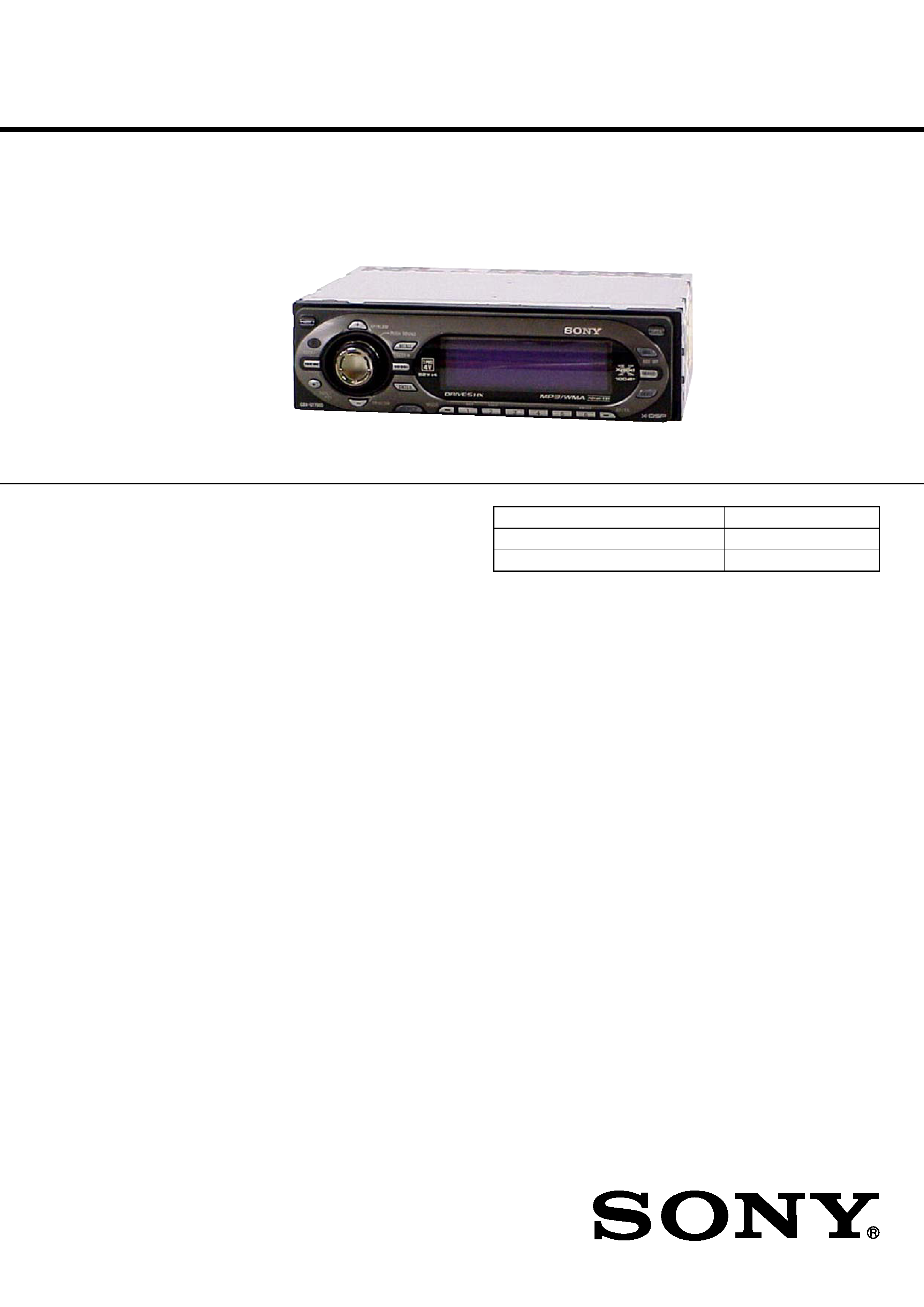
CDX-GT705DX
AEP Model
UK Model
E Model
CDX-GT700D
9-887-002-01
2005L04-1
© 2005.12
Ver. 1.0 2005.12
SPECIFICATIONS
CDX-GT700D/GT705DX
Power amplifier section
Outputs
Speaker outputs (sure seal connectors)
Speaker impedance
4 8 ohms
Maximum power output
52 W
× 4 (at 4 ohms)
General
Outputs
Audio outputs terminal (front/rear)
Subwoofer output terminal (mono)
Power antenna relay control terminal
Power amplifier control terminal
Inputs
Telephone ATT control terminal
Illumination control terminal
BUS control input terminal
BUS audio input/AUX IN terminal
Remote controller input terminal
Antenna input terminal
Loudness
+8 dB at 100 Hz
+0 dB at 10 kHz
· The tuner and CD sections have no adjustments.
CD player section
Signal-to-noise ratio
120 dB
Frequency response
10 20,000 Hz
Wow and flutter
Below measurable limit
Tuner section
FM
Tuning range
CDX-GT705DX: 87.5 107.9 MHz
CDX-GT700D: 87.5 108 MHz
Antenna terminal
External antenna connector
Intermediate frequency
10.7 MHz/450 kHz
Usable sensitivity
9 dBf
Selectivity
75 dB at 400 kHz
Signal-to-noise ratio
67 dB (stereo), 69 dB (mono)
Harmonic distortion at 1 kHz
0.5% (stereo), 0.3% (mono)
Separation
35 dB at 1 kHz
Frequency response
30 15,000 Hz
AM (CDX-GT705DX)
Tuning range
530 1,710 kHz
Antenna terminal
External antenna connector
Intermediate frequency
10.7 MHz/450 kHz
Sensitivity
30
µV
MW/LW (CDX-GT700D)
Tuning range
MW: 531 1,602 kHz
LW: 153 279 kHz
Antenna terminal
External antenna connector
Intermediate frequency
10.7 MHz/450 kHz
Sensitivity
MW: 30
µV
LW: 40
µV
AUDIO POWER SPECIFICATIONS (US MODEL)
POWER OUTPUT AND TOTAL HARMONIC DISTORTION
23.2 watts per channel minimum continuous average power into
4 ohms, 4 channels driven from 20 Hz to 20 kHz with no more
than 5% total harmonic distortion.
FM/AM COMPACT DISC PLAYER
CDX-GT705DX
FM/MW/LW COMPACT DISC PLAYER
CDX-GT700D
Continued on next page
Photo: CDX-GT700D
Model Name Using Similar Mechanism
CDX-GT800D/GT805DX
CD Drive Mechanism Type
MG-611WD-186//Q
Optical Pick-up Name
KSS1000E
2
CDX-GT700D/GT705DX
SAFETY-RELATED COMPONENT WARNING!!
COMPONENTS IDENTIFIED BY MARK 0 OR DOTTED LINE
WITH MARK 0 ON THE SCHEMATIC DIAGRAMS AND IN
THE PARTS LIST ARE CRITICAL TO SAFE OPERATION.
REPLACE THESE
COMPONENTS WITH
SONY
PARTS
WHOSE PART NUMBERS APPEAR AS SHOWN IN THIS
MANUAL OR IN SUPPLEMENTS PUBLISHED BY SONY.
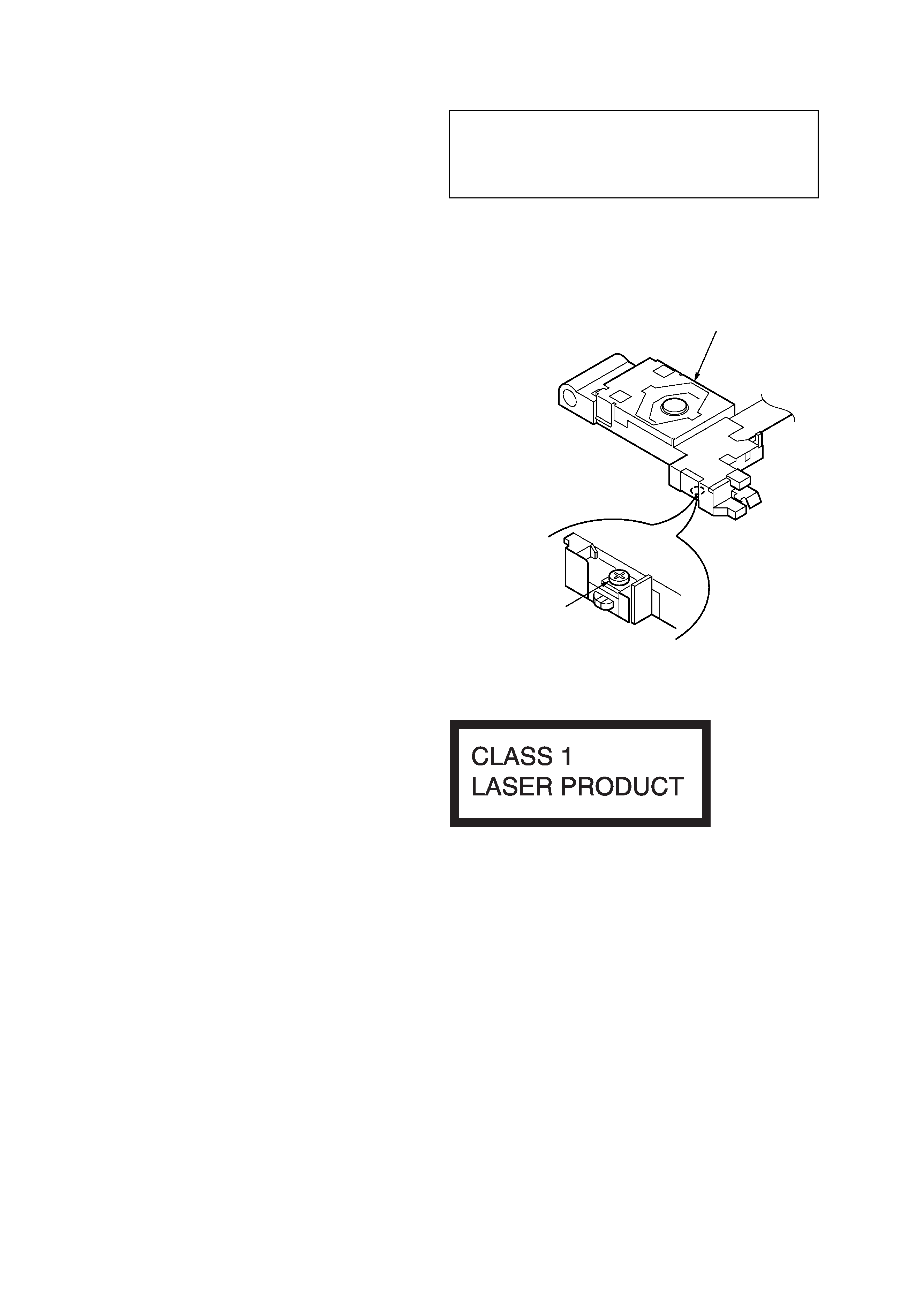
NOTES ON HANDLING THE OPTICAL PICK-UP BLOCK
OR BASE UNIT
The laser diode in the optical pick-up block may suffer electrostatic
breakdown because of the potential difference generated by the
charged electrostatic load, etc. on clothing and the human body.
During repair, pay attention to electrostatic breakdown and also use
the procedure in the printed matter which is included in the repair
parts.
The flexible board is easily damaged and should be handled with
care.
NOTES ON LASER DIODE EMISSION CHECK
The laser beam on this model is concentrated so as to be focused on
the disc reflective surface by the objective lens in the optical pick-
up block. Therefore, when checking the laser diode emission,
observe from more than 30 cm away from the objective lens.
Notes on Chip Component Replacement
· Never reuse a disconnected chip component.
· Notice that the minus side of a tantalum capacitor may be damaged
by heat.
TEST DISCS
This set can playback CD-R and CD-ROM discs. The following
test discs should be used to check the capability:
CD-R test disc TCD-R082LMT (Part No. J-2502-063-1)
CD-RW test disc TCD-W082L (Part No. J-2502-063-2)
If the optical pick-up block is defective, please replace the whole
optical pick-up block.
Never turn the semi-fixed resistor located at the side of optical pick-
up block.
optical pick-up
semi-fixed resistor
SERVICE NOTES
This label is located on the bottom of the chassis.
CAUTION
Use of controls or adjustments or performance of procedures
other than those specified herein may result in hazardous
radiation exposure.
Power requirements
12 V DC car battery
(negative ground)
Dimensions
Approx. 178
× 50 × 180 mm
(7 1/8
× 2 × 7 1/8 in.) (w/h/d)
Mounting dimensions
Approx. 182
× 53 × 162 mm
(7 1/4
× 2 1/8 × 6 1/2 in.) (w/h/d)
Mass
Approx. 1.3 kg
(3 lb 5 oz)
Supplied accessories
Parts for installation and connections (1 set)
Card remote commander RM-X152
(CDX-GT705DX)
Card remote commander RM-X154
(CDX-GT700D)
US and foreign patents licensed from Dolby Laboratories.
Note
This unit cannot be connected to a digital preamplifier or an equalizer
which is Sony BUS system compatible.
Design and specifications are subject to change without
notice.
· CDX-GT700D model
ATTENTION AU COMPOSANT AYANT RAPPORT
À LA SÉCURITÉ!!
LES COMPOSANTS IDENTIFIÉS PAR UNE MARQUE 0 SUR LES
DIAGRAMMES SCHÉMATIQUES ET LA LISTE DES PIÈCES SONT
CRITIQUES POUR LA SÉCURITÉ DE FONCTIONNEMENT. NE
REMPLACER CES COMPOSANTS QUE PAR DES PIÈCES SONY
DONT LES NUMÉROS SONT DONNÉS DANS CE MANUEL OU
DANS LES SUPPLÉMENTS PUBLIÉS PAR SONY.
3
CDX-GT700D/GT705DX
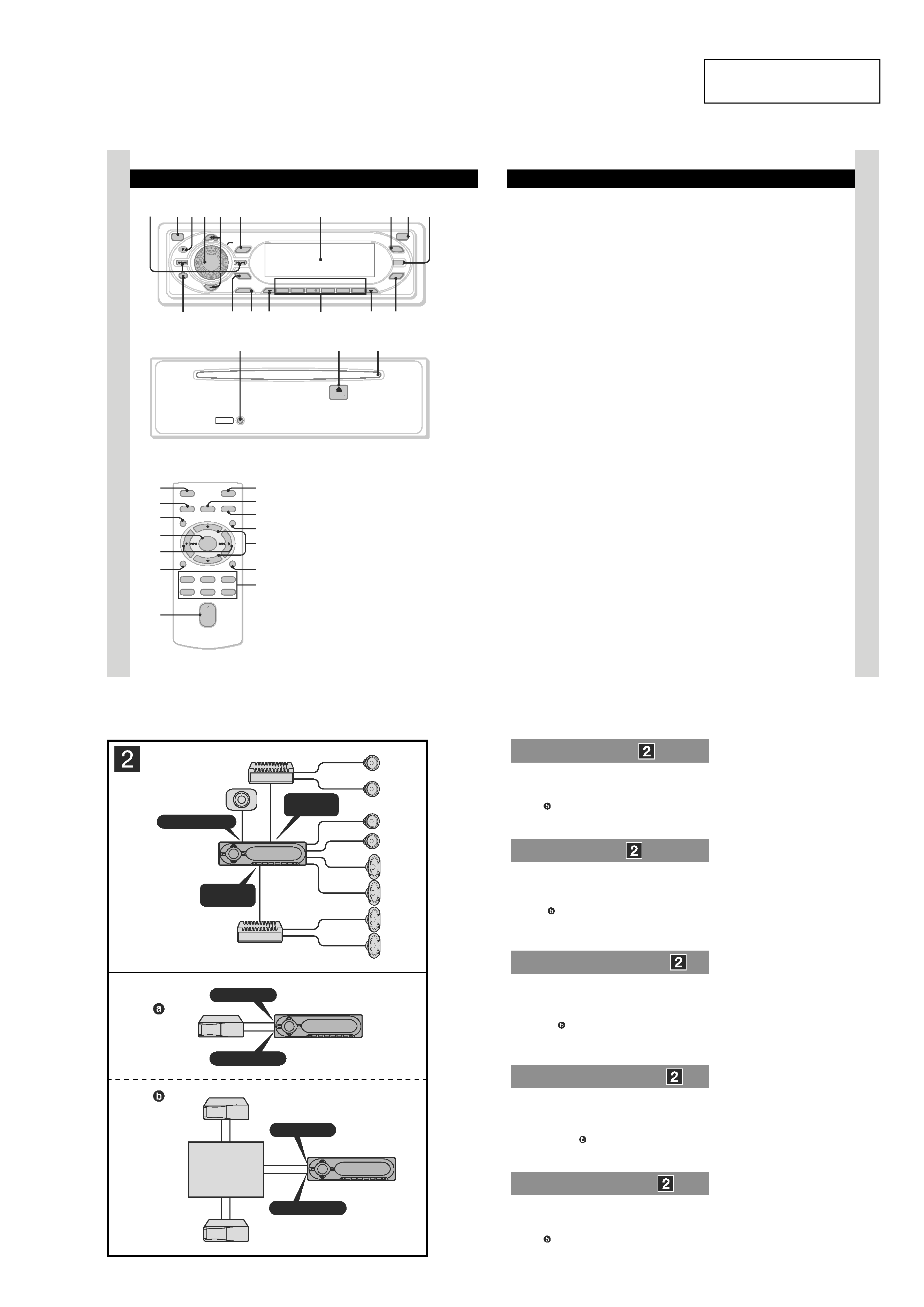
SERVO BOARD
CN2
MAIN BOARD
CNP301
J-2502-076-1
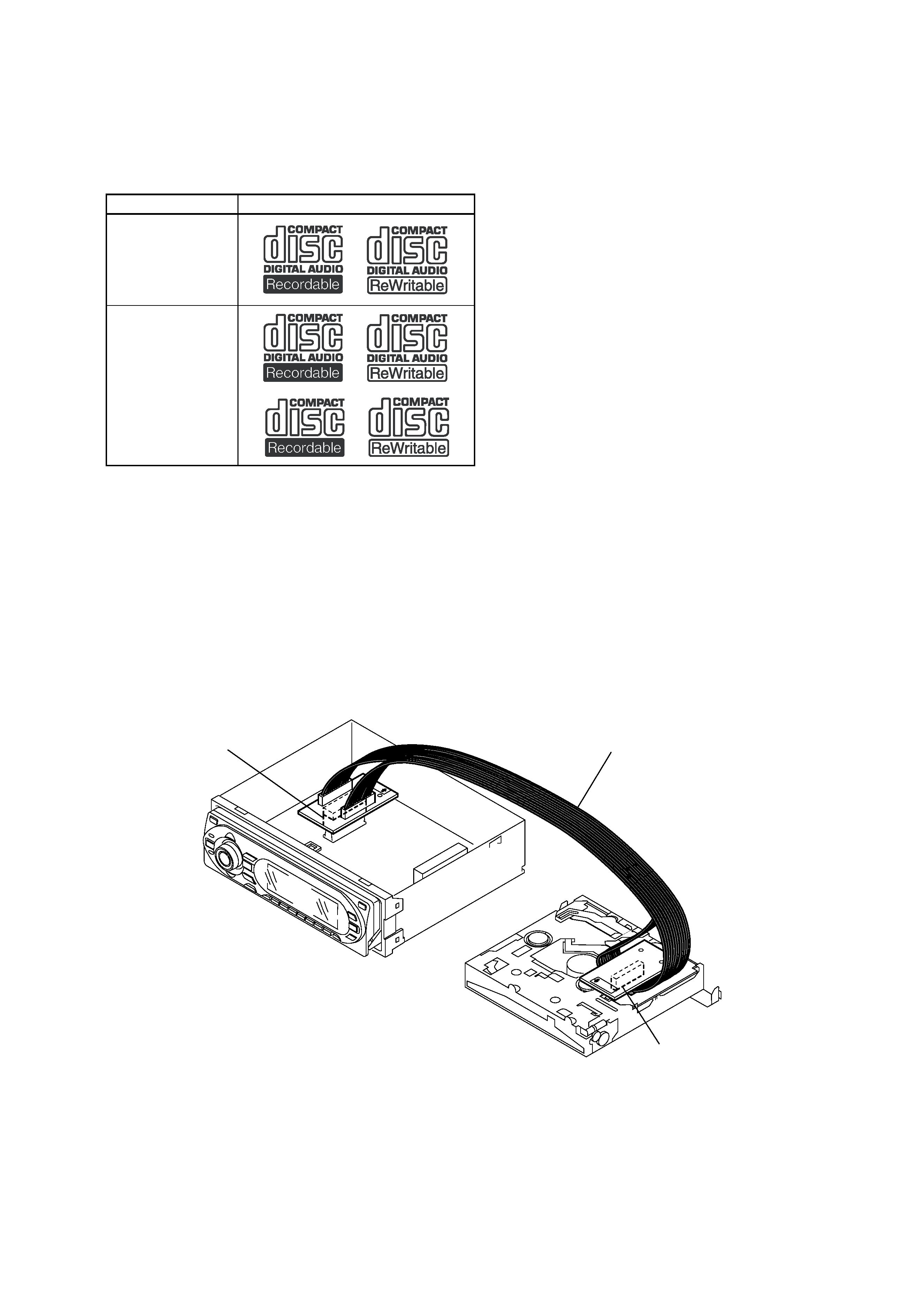
· CD Playback:
You can play CD-DA (also containing CD TEXT*1), CD-R/CD-
RW (MP3/WMA files also containing Multi Session and ATRAC
CD (ATRAC3 and ATRAC3plus format).
Type of discs
Label on the disc
CD-DA
MP3
WMA
ATRAC CD
*1 A CD TEXT disc is a CD-DA that includes information such as
disc, artist and track name.
EXTENSION CABLE AND SERVICE POSITION
When repairing or servicing this set, connect the jig (extension cable)
as shown below.
· Connect the MAIN board (CNP301) and the SERVO board (CN2)
with the extension cable (Part No. J-2502-076-1).

4
CDX-GT700D/GT705DX
TABLE OF CONTENTS
1.
GENERAL
Location of Controls ........................................................
5
Connections .....................................................................
5
2.
DISASSEMBLY
2-1.
Sub (FL) Panel Assy ........................................................ 12
2-2.
CD Mechanism Block ..................................................... 12
2-3.
Main Board ...................................................................... 13
2-4.
Chassis (T) Sub Assy ....................................................... 13
2-5.
Roller Arm Assy .............................................................. 14
2-6.
Chassis (OP) Assy ........................................................... 14
2-7.
Optical Pick-up ................................................................ 15
2-8.
SL Motor Assy (M902) ................................................... 15
2-9.
LE Motor Assy (M903) ................................................... 16
2-10. Servo Board ..................................................................... 16
3.
DIAGNOSIS FUNCTION ........................................ 17
4.
DIAGRAMS
4-1.
Block Diagram CD Section ......................................... 19
4-2.
Block Diagram Main Section ...................................... 20
4-3.
Block Diagram Display Section .................................. 21
4-4.
Circuit Boards Location .................................................. 22
4-5.
Printed Wiring Boards CD Mechanism Section .......... 23
4-6.
Schematic Diagram CD Mechanism Section (1/2) ..... 24
4-7.
Schematic Diagram CD Mechanism Section (2/2) ..... 25
4-8.
Printed Wiring Board Main Section ............................ 26
4-9.
Schematic Diagram Main Section (1/4) ...................... 28
4-10. Schematic Diagram Main Section (2/4) ...................... 29
4-11. Schematic Diagram Main Section (3/4) ...................... 30
4-12. Schematic Diagram Main Section (4/4) ...................... 31
4-13. Printed Wiring Boards Sub Section ............................. 32
4-14. Printed Wiring Board Display Section ........................ 33
4-15. Schematic Diagram Display Section ........................... 34
5.
EXPLODED VIEWS
5-1.
Main Section .................................................................... 46
5-2.
Front Panel Section ......................................................... 47
5-3.
CD Mechanism Section (1) ............................................. 48
5-4.
CD Mechanism Section (2) ............................................. 49
5-5.
CD Mechanism Section (3) ............................................. 50
5-6.
CD Mechanism Section (4) ............................................. 51
6.
ELECTRICAL PARTS LIST .................................. 52
·UNLEADED SOLDER
Boards requiring use of unleaded solder are printed with the lead-
free mark (LF) indicating the solder contains no lead.
(Caution: Some printed circuit boards may not come printed with
the lead free mark due to their particular size.)
: LEAD FREE MARK
Unleaded solder has the following characteristics.
· Unleaded solder melts at a temperature about 40
°C higher than
ordinary solder.
Ordinary soldering irons can be used but the iron tip has to be
applied to the solder joint for a slightly longer time.
Soldering irons using a temperature regulator should be set to
about 350
°C.
Caution: The printed pattern (copper foil) may peel away if the
heated tip is applied for too long, so be careful!
· Strong viscosity
Unleaded solder is more viscous (sticky, less prone to flow)
than ordinary solder so use caution not to let solder bridges
occur such as on IC pins, etc.
· Usable with ordinary solder
It is best to use only unleaded solder but unleaded solder may
also be added to ordinary solder.
5
CDX-GT700D/GT705DX
SECTION 1
GENERAL
· LOCATION OF CONTROLS
· CDX-GT700D (AEP, UK Model)
6
Location of controls and basic operations
Main unit
Front panel removed
Card remote commander
RM-X154
Refer to the pages listed for details. The
corresponding buttons on the card remote
commander control the same functions as those
on the unit.
A SEEK /+ buttons
CD:
To skip tracks (press); skip tracks
continuously (press, then press again within
about 1 second and hold); fast-forward/
reverse a track (press and hold).
Radio:
To tune in stations automatically (press); find
a station manually (press and hold).
B OFF button
To power off/stop the source.
C Receptor
To receive signals from the card remote
commander.
D VOL (volume) control dial/SOUND
button 16
To adjust volume (rotate); select sound items
(press).
MENU
ENTER
SOURCE
1
2
3
4
5
6
OFF
OPEN
HDEQ
BBE
BBE MP
SEEK
SEEK+
DSPL/
PTY
GP/ALBM
GP/ALBM
MODE
AF/TA
REP
SHUF
PAUSE
PUSH SOUND
IMAGE
CDX-GT700D
12 34 5
8
7q;
qa
qg
qs qd qf
qj
qh
RESET
qk
ql
w;
OFF
DSPL/PTY
REP
SHUF
MENU
LIST
SCRL
SOURCE
SOUND
MODE
PAUSE
13
2
46
5
ATT
VOL
+
+
ENTER
qd
wg
6
wf
qf
2
wj
qs
wa
qa
wd
ws
qg
wh
6
9
7
E GP*1/ALBM*2 +/ buttons*3
To select preset stations/skip groups (press);
skip groups continuously (press and hold).
F MENU button
To enter menu.
G Display window
H BBE MP button 2, 12, 13
To activate the BBE MP function.
I OPEN button 5
J IMAGE button 2
To select the display image.
Movie mode 1-3 t Spectrum analyzer
mode 1-5 t Space Producer mode t Wall
paper mode 1-3 t normal play/reception
mode
K DSPL (display)/PTY (Programme
Type) button 8, 10
To change display items; to select PTY in
RDS.
L ENTER button
To complete a setting.
M SOURCE button
To power on/change the source (Radio/CD/
MD*5/AUX).
N MODE button 8, 17
To select the radio band (FM/MW/LW)/
select the unit*4.
O Number buttons
Radio:
To receive stored stations (press); store
stations (press and hold).
CD/MD*5:
(1): REP 8, 18
(2): SHUF 8, 18
(6): PAUSE*6
To pause playback. To cancel, press again.
P AF (Alternative Frequencies)/TA
(Traffic Announcement) button 10
To set AF and TA/TP in RDS.
Q HDEQ button 11, 12
To select an equalizer type (Flat, Xplod,
Refined Vocal, Over Drive, Virtual Sub,
Natural Cruise or Rear Drive)
R RESET button 4
S Z (eject) button 5
To eject the disc.
T Disc slot 5
To insert the disc.
The following buttons on the card remote
commander have also different buttons/functions
from the unit.
wa </, (SEEK /+) buttons
To control CD/Radio, the same as (SEEK)
/+ on the unit.
ws VOL (volume) +/ button
To adjust volume.
wd ATT (attenuate) button
To attenuate the sound. To cancel, press
again.
wf SOUND button
To select sound items.
wg LIST button 9, 18
To list up.
wh M/m (+/) buttons
To control CD, the same as (GP/ALBM) +/
on the unit.
wj SCRL (scroll) button 8
To scroll the display item.
*1 When an ATRAC CD is played.
*2 When an MP3/WMA is played.
*3 If the changer is connected, the operation is
different, see page 17.
*4 When a CD/MD changer is connected.
*5 When an MD changer is connected.
*6 When playing back on this unit.
Note
If the unit is turned off and the display disappears, it
cannot be operated with the card remote commander
unless (SOURCE) on the unit is pressed, or a disc is
inserted to activate the unit first.
Tip
For details on how to replace the battery, see
"Replacing the lithium battery of the card remote
commander" on page 21.
This section is extracted
from instruction manual.
· CONNECTIONS
· CDX-GT700D (AEP, UK Model)
AUDIO OUT
FRONT
AUDIO OUT
REAR
SUB OUT (MONO)
BUS AUDIO IN
BUS CONTROL IN
A
B
BUS AUDIO IN
BUS CONTROL IN
Source selector*
Signalquellenwähler*
Sélecteur de source*
Selettore di fonte*
Geluidsbronkiezer*
XA-C30
* not supplied
nicht mitgeliefert
non fourni
non in dotazione
niet bijgeleverd
Connection example
Notes (2-A)
· Be sure to connect the earth lead before connecting the
amplifier.
· The alarm will only sound if the built-in amplifier is used.
Tip (2-B- )
For connecting two or more CD/MD changers, the source
selector XA-C30 (not supplied) is necessary.
Anschlussbeispiel
Hinweise (2-A)
· Schließen Sie unbedingt zuerst das Massekabel an, bevor Sie
den Verstärker anschließen.
· Der Signalton wird nur ausgegeben, wenn der integrierte
Verstärker verwendet wird.
Tipp (2-B- )
Zum Anschließen von zwei oder mehr CD/MD-Wechslern wird
der Signalquellenwähler Cuight mitgeliefert (night mitgeliefert)
XA-C30 benötigt.
Exemple de raccordement
Remarques (2-A)
· Raccordez d'abord le câble de mise à la masse avant de
connecter l'amplificateur.
· Un bip est émis uniquement lorsque l'amplificateur intégré est
utilisé.
Conseil (2-B- )
Dans le cas du raccordement de deux changeurs de CD/MD
ou plus, le sélecteur de source XA-C30 (non fourni) est
indispensable.
Esempio di collegamento
Note (2-A)
· Assicurarsi di collegare il cavo di terra prima di collegare
l'amplificatore.
· Il segnale acustico viene emesso solo se viene utilizzato
l'amplificatore incorporato.
Suggerimento (2-B- )
Per collegare due o più cambia CD/MD, si deve utilizzare il
selettore di fonte XA-C30 (non in dotazione).
Voorbeeldaansluitingen
Opmerkingen (2-A)
· Sluit eerst de aarddraad aan voordat u de versterker aansluit.
· U hoort de pieptoon alleen als de ingebouwde versterker wordt
gebruikt.
Tip (2-B- )
Om twee of meer CD/MD-wisselaars aan te sluiten, hebt u de
geluidsbronkiezer XA-C30 (niet bijgeleverd) nodig.