COMPACT DISC CHANGER
US Model
Canadian Model
AEP Model
UK Model
E Model
SERVICE MANUAL
CDX-805
Continued on next page
Photo: Except US model
Model Name Using Similar Mechanism
NEW
CD Drive Mechanism Type
MG-250A-137
Optical Pick-up Name
KSS-521A/J2RP
SPECIFICATIONS
System
Compact disc digital audio system
Laser diode properties
Material: GaAlAs
Wavelength: 780 nm
Emission Duration: Continuous
Laser Output Power: Less than
44.6 µW*
* This output is the value
measured at a distance of 200
mm from the objective lens
surface on the Optical Pick-up
Block.
Frequency respones
520,000 Hz
Wow and flutter Below the measurable limit
Signal-to-noise ratio
99 dB
Outputs
Optical digital output
BUS control output (8 PIN)
Analog audio output (RCA PIN)
Current drain
800 mA (during CD playback)
800 mA (during loading or
ejecting a disc)
Operating temperature
10°C to +55°C (14°F to 131°F)
Dimensions
Approx. 262
× 90 × 181.5 mm
(103/8
× 35/8 × 71/4 in.) (w/h/d)
not incl. projecting parts and
controls
Mass
Approx. 2.1 kg (4 lb. 10 oz.)
Power requirement
12V DC car battery (negative
ground)
Supplied accessories
Disc magazine (1)
Parts for installation and
connections (1 set)
Design and specifications subject to change without
notice.
Ver 1.1 2001.08
9-925-522-12
Sony Corporation
2001H0500-1
e Vehicle Company
C
2001.8
Shinagawa Tec Service Manual Production Group

2
ATTENTION AU COMPOSANT AYANT RAPPORT
À LA SÉCURITÉ!
LES COMPOSANTS IDENTIFIÉS PAR UNE MARQUE
!
SUR LES DIAGRAMMES SCHÉMATIQUES ET LA LISTE
DES PIÈCES SONT CRITIQUES POUR LA SÉCURITÉ
DE FONCTIONNEMENT. NE REMPLACER CES COM-
POSANTS QUE PAR DES PIÈCES SONY DONT LES
NUMÉROS SONT DONNÉS DANS CE MANUEL OU
DANS LES SUPPLÉMENTS PUBLIÉS PAR SONY.
TABLE OF CONTENTS
1.
GENERAL
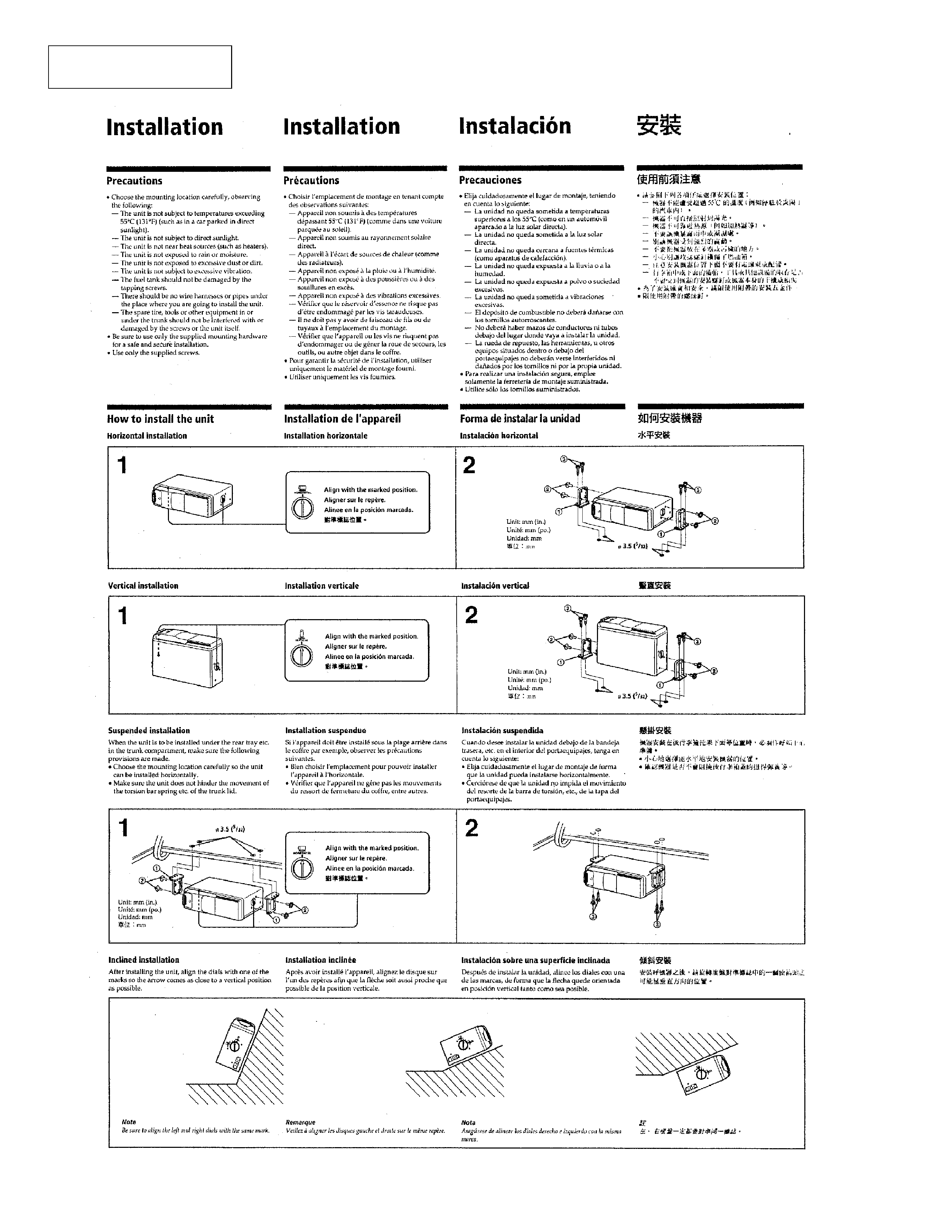
Installation .........................................................................
4
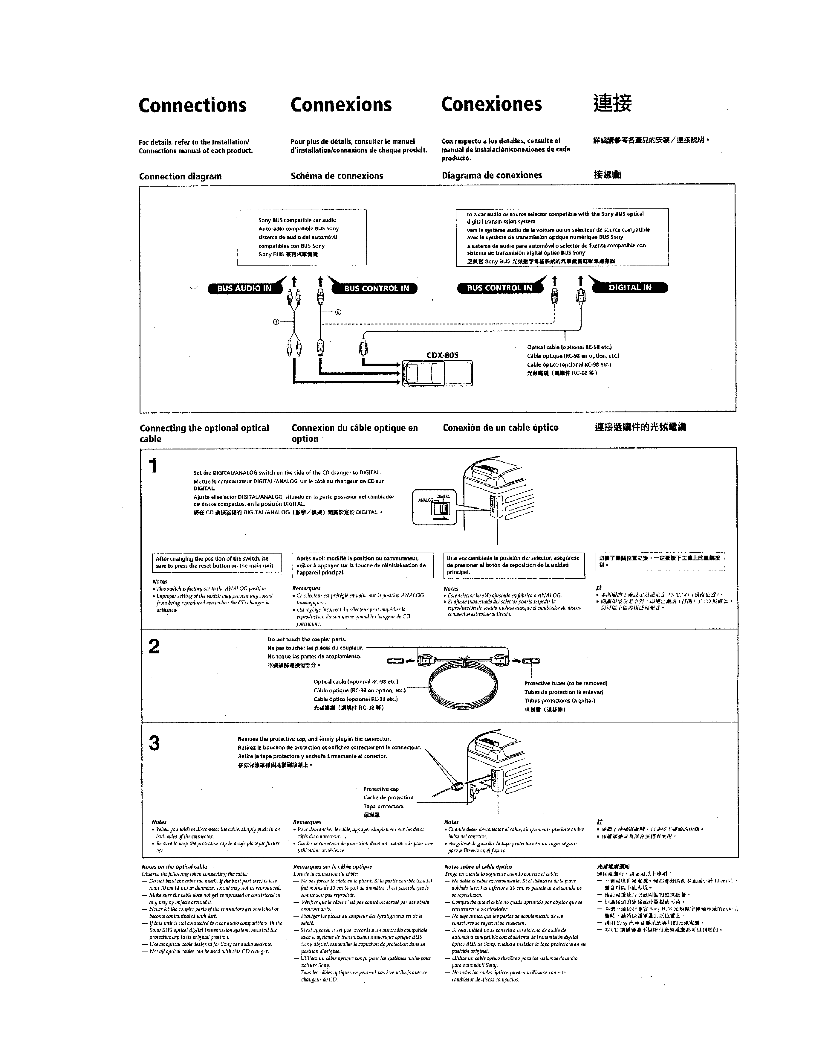
Connections .......................................................................
5
2.
DISASSEMBLY ............................................................ 7
3.
ELECTRICAL ADJUSTMENTS ........................... 13
4.
DIAGRAMS
4-1. Block Diagram ................................................................... 15
4-2. Printed Wiring Board RF Section ................................ 17
4-3. Schematic Diagram RF Section ................................... 19
4-4. Schematic Diagram MAIN Section ............................. 23
4-5. Printed Wiring Board MAIN Section .......................... 27
4-6. IC Pin Function Description .............................................. 35
5.
EXPLODED VIEWS ................................................... 38
6.
ELECTRICAL PARTS LIST .................................... 43
The laser diode in the optical pick-up block may suffer electrostatic
breakdown because of the potential difference generated by the
charged electrostatic load, etc. on clothing and the human body.
During repair, pay attention to electrostatic breakdown and also use
the procedure in the printed matter which is included in the repair
parts.
The flexible board is easily damaged and should be handled with
care.
NOTES ON HANDLING THE OPTICAL PICK-UP
BLOCK OR BASE UNIT
Laser Diode Properites
· Material: GaAlAs
· Wavelength: 780 nm
· Emission Duration: continuous
· Laser Output Power: less than 44.6 µW*
* This output is the value measured at a distance of 200 mm
from the objective lens surface on the Optical Pick-up Block.
CAUTION
Use of controls or adjustments or performance of
procedures other than those specified herein may
result in hazardous radiation exposure.
Flexible Circuit Board Repairing
· Keep the temperature of the soldering iron around 270 °C during
repairing.
· Do not touch the soldering iron on the same conductor of the
circuit board (within 3 times).
· Be careful not to apply force on the conductor when soldering or
unsoldering.
Notes on chip component replacement
· Never reuse a disconnected chip component.
· Notice that the minus side of a tantalum capacitor may be dam-
aged by heat.
SAFETY-RELATED COMPONENT WARNING!!
COMPONENTS IDENTIFIED BY MARK
! OR DOTTED
LINE WITH MARK
! ON THE SCHEMATIC DIAGRAMS
AND IN THE PARTS LIST ARE CRITICAL TO SAFE
OPERATION. REPLACE THESE COMPONENTS WITH
SONY PARTS WHOSE PART NUMBERS APPEAR AS
SHOWN IN THIS MANUAL OR IN SUPPLEMENTS PUB-
LISHED BY SONY.
SERVICING NOTES
3
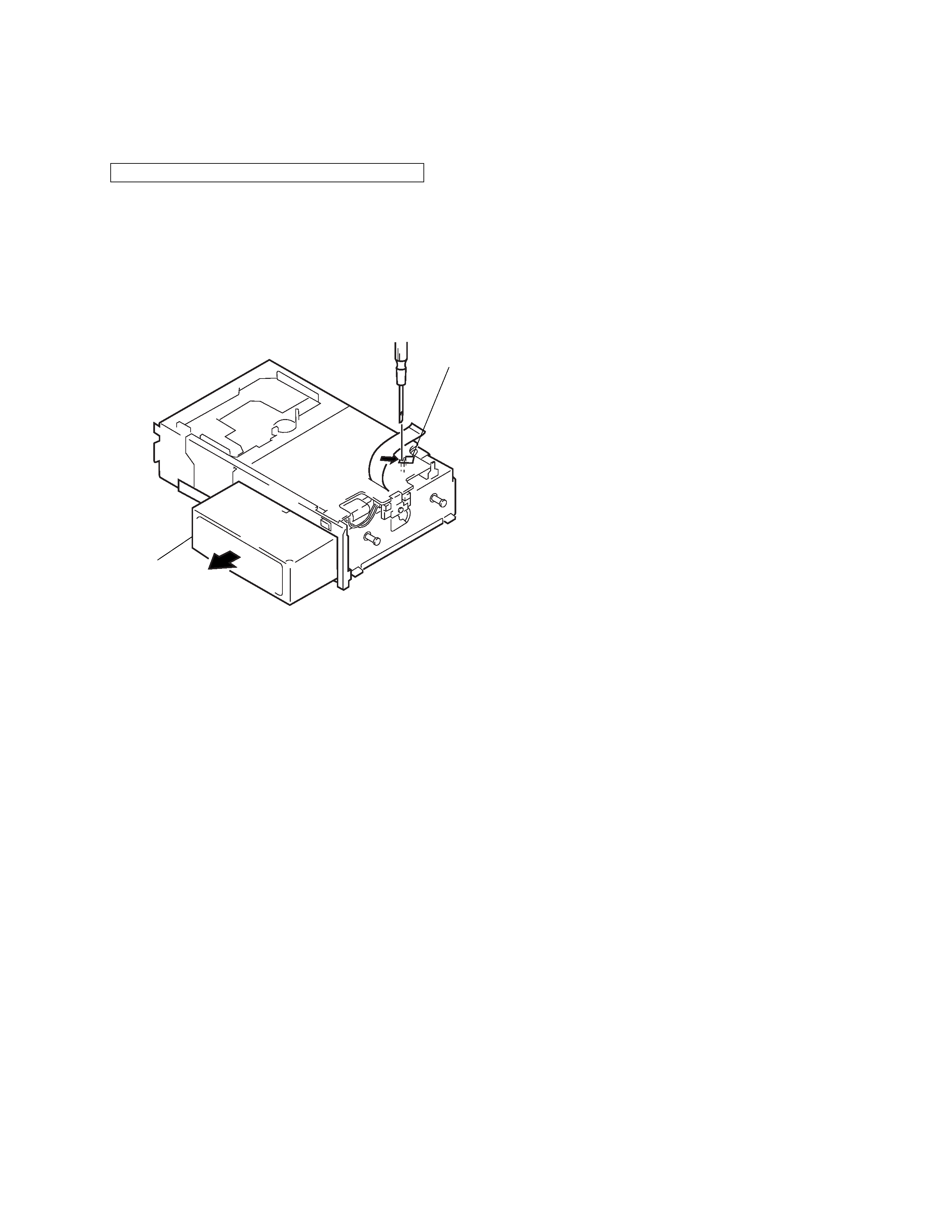
Lever (stop) ass'y
Magazine ass'y
DISC MAGAZINE GETTING OUT PROCEDURE ON THE
POWER SUPPLY IS OFF
Remove the CASE (LOWER) assembly beforehand
1) Press the lever (stop) assy to arrow direction.
2) Removal the magazine assy.
Note: Take out the magazine only when the tray is completely within
the magazine. If the disk or tray is sticking out, turn on the
power and eject the magazine.
4
SECTION 1
GENERAL
This section is extracted
from instruction manual.
5