SERVICE MANUAL
COMPACT DISC CHANGER SYSTEM
SPECIFICATIONS
CDX-555RF/555XRF
Photo: CDX-555XRF
Model Name Using Similar Mechanism
CDX-540RF/545RF
CD Drive Mechanism Type
MG-251A-137
Optical Pick-up Name
KSS-720A
US Model
Canadian Model
CDX-555RF
E Model
CDX-555XRF
Ver 1.2 2002.10
9-873-374-03
Sony Corporation
2002J0500-1
e Vehicle Company
C
2002.10
Published by Sony Engineering Corporation
CD changer
System
Compact disc digital audio
system
Transmitting frequency
88.3 MHz/88.5 MHz/
88.7 MHz/88.9 MHz/
89.1 MHz/89.3 MHz/
89.5 MHz/89.7 MHz/
89.9 MHz (switchable)
Input/output terminals
Wired remote control
(8 pin)
RF signal (FM) output
Power input(3 pin)
Current drain
800 mA (at playback)
800 mA (at disc loading /
ejecting)
Operating temperature
10
°C to +55°C
(14
°F to 131°F)
Dimensions
Approx.262
× 90 × 185 mm
(10 3/8
× 3 5/8 × 7 3/8 in.)
(w/h/d)
Mass
Approx.2.1 kg (4 lb. 10 oz.)
Relay box
Input/output
Aerial input terminal
Aerialoutputcord
CD changer inputcord
Wired remote (RM-X80RF)
Dimensions
Approx.
122
× 36.5 × 15.5 mm
(4 3/8
× 1 7/16 × 5/8 in.)
(w/h/d)
Mass
Approx.255 g (9 oz.)
Wireless remote (RM-X81RF)
Dimensions
Approx.
52
× 8.5 × 90 mm
(2 1/16
× 3/8 × 3 9/16 in.)
(w/h/d)
Mass
Approx. 30 g (1 oz.) not
incl. battery
Battery
Lithium battery (CR2025)
General
Supplied accessories
Disc magazine (1)
Parts for installation and
connections (1 set)
Design and specifications are subject to change
without notice.
Laser Diode Properties
Material
GaAlAs
Wavelength
780 nm
Emission Duration
Continuous
Laser output power
Less than 44.6
µW*
* This output is the value measured at a distance of
200 mm from the objective lens surface on the
Optical Pick-up Block.
Dimensions
Approx.
40
× 40 × 27 mm
(1 5/8
× 1 5/8 × 1 1/8 in.)
(w/h/d)
Mass
Approx.140 g (5 oz.)
2
CDX-555RF/555XRF
ATTENTION AU COMPOSANT AYANT RAPPORT
À LA SÉCURITÉ!
LES COMPOSANTS IDENTIFIÉS PAR UNE MARQUE 0
SUR LES DIAGRAMMES SCHÉMATIQUES ET LA LISTE
DES PIÈCES SONT CRITIQUES POUR LA SÉCURITÉ
DE FONCTIONNEMENT. NE REMPLACER CES COM-
POSANTS QUE PAR DES PIÈCES SONY DONT LES
NUMÉROS SONT DONNÉS DANS CE MANUEL OU
DANS LES SUPPLÉMENTS PUBLIÉS PAR SONY.
SAFETY-RELATED COMPONENT WARNING!!
COMPONENTS IDENTIFIED BY MARK 0 OR DOTTED
LINE WITH MARK 0 ON THE SCHEMATIC DIAGRAMS
AND IN THE PARTS LIST ARE CRITICAL TO SAFE
OPERATION. REPLACE THESE COMPONENTS WITH
SONY PARTS WHOSE PART NUMBERS APPEAR AS
SHOWN IN THIS MANUAL OR IN SUPPLEMENTS PUB-
LISHED BY SONY.
TABLE OF CONTENTS
1.
SERVICING NOTES ................................................ 3
2.
GENERAL
Location of Controls .......................................................
4
Installation .......................................................................
6
Connections .....................................................................
8
3.
DISASSEMBLY
3-1. Disassembly Flow ...........................................................
9
3-2. Case, (Upper.T), Front Panel Assy ................................. 10
3-3. Mechanism Deck (MG-251A-137) ................................ 10
3-4. FM Board ........................................................................ 11
3-5. MAIN Board, Slide Variable Resistor
(Elevator Height Sensor) (RV202) ................................. 11
3-6. ELJ Motor Assy (Elevator) (M104) ................................ 12
3-7. Escutcheon (T) ................................................................ 12
3-8. Chassis (U.S) Sub Assy .................................................. 13
3-9. Chassis Assy .................................................................... 13
3-10. RF Board ......................................................................... 14
3-11. Sled Motor Assy (251) (M101),
Optical Pick-up (KSS-720A) .......................................... 14
3-12. LSW Board, Spindle Motor (S) Sub Assy (M102) ........ 15
3-13. ELJ Motor Assy (Chucking) (M103) ............................. 15
4.
ASSEMBLY
4-1. Assembly Flow ................................................................ 16
4-2. Optical Pick-up Complete Assy ...................................... 16
4-3. Gear (Lomini)/(Load 1) Assy ......................................... 17
4-4. Operation Check ............................................................. 17
5.
MECHANICAL ADJUSTMENT .......................... 18
6.
ELECTRICAL CHECK .......................................... 19
7.
DIAGRAMS
7-1. Block Diagram SERVO Section .............................. 21
7-2. Block Diagram MAIN Section ................................ 22
7-3. Note for Printed Wiring Boards and
Schematic Diagrams ....................................................... 23
7-4. Printed Wiring Boards RF/LSW Boards ................. 24
7-5. Schematic Diagram RF/LSW Boards ...................... 25
7-6. Printed Wiring Board
MAIN Board (Component Side) .............................. 26
7-7. Printed Wiring Boards
MAIN (Conductor Side)/SW Boards ....................... 27
7-8. Schematic Diagram MAIN Board (1/2) .................. 28
7-9. Schematic Diagram MAIN (2/2)/SW Boards ......... 29
7-10. Printed Wiring Board FM Board ............................. 30
7-11. Schematic Diagram FM Board ................................. 31
7-12. IC Pin Function Description ........................................... 36
8.
EXPLODED VIEWS
8-1. General Section-1 ............................................................ 38
8-2. General Section-2 ............................................................ 39
8-3. Mechanism Deck Section-1 (MG-251A-137) ................ 40
8-4. Mechanism Deck Section-2 (MG-251A-137) ................ 41
8-5. Mechanism Deck Section-3 (MG-251A-137) ................ 42
8-6. Mechanism Deck Section-4 (MG-251A-137) ................ 43
9.
ELECTRICAL PARTS LIST ............................... 44
Notes on chip component replacement
· Never reuse a disconnected chip component.
· Notice that the minus side of a tantalum capacitor may be dam-
aged by heat.
Flexible Circuit Board Repairing
· Keep the temperature of the soldering iron around 270 °C dur-
ing repairing.
· Do not touch the soldering iron on the same conductor of the
circuit board (within 3 times).
· Be careful not to apply force on the conductor when soldering
or unsoldering.
CAUTION
Use of controls or adjustments or performance of procedures
other than those specified herein may result in hazardous ra-
diation exposure.
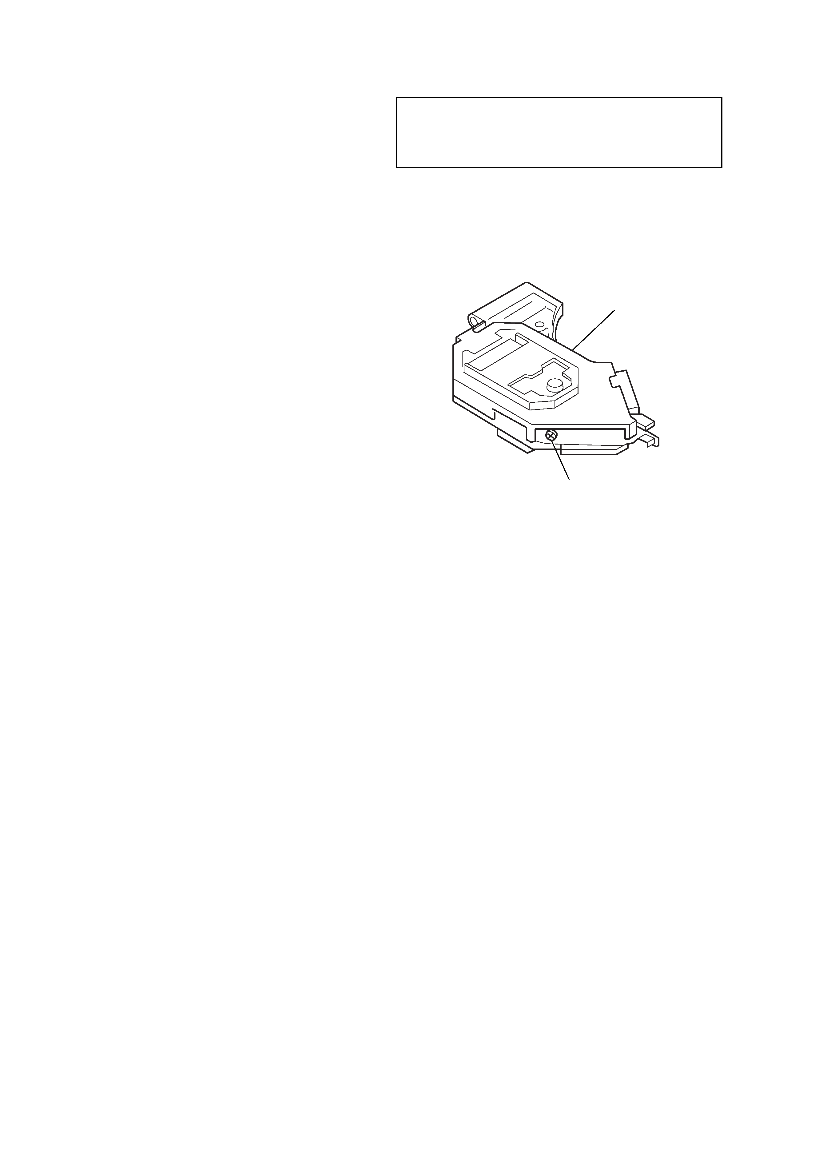
OPTICAL
PICK-UP
BLOCK
SEMI-FIXED
RESISTOR
US/Canadian model:
If the optical pick-up block is defective, please replace the whole
optical pick-up block.
Never turn the semi-fixed resistor located at the side of optical
pick-up block.
3
CDX-555RF/555XRF
SECTION 1
SERVICING NOTES
NOTES ON HANDLING THE OPTICAL PICK-
UP BLOCK OR BASE UNIT
The laser diode in the optical pick-up block may suffer electro-
static breakdown because of the potential difference generated by
the charged electrostatic load, etc. on clothing and the human body.
During repair, pay attention to electrostatic breakdown and also
use the procedure in the printed matter which is included in the
repair parts.
The flexible board is easily damaged and should be handled with
care.
NOTES ON LASER DIODE EMISSION CHECK
The laser beam on this model is concentrated so as to be focused
on the disc reflective surface by the objective lens in the optical
pick-up block. Therefore, when checking the laser diode emis-
sion, observe from more than 30 cm away from the objective lens.
TEST DISC
This set can playback a CD-R, CD-RW for audio use.
When test this set, use the following test disc.
Test disc for CD-R: TCD-R082LMT (Part No.: J-2502-063-1)
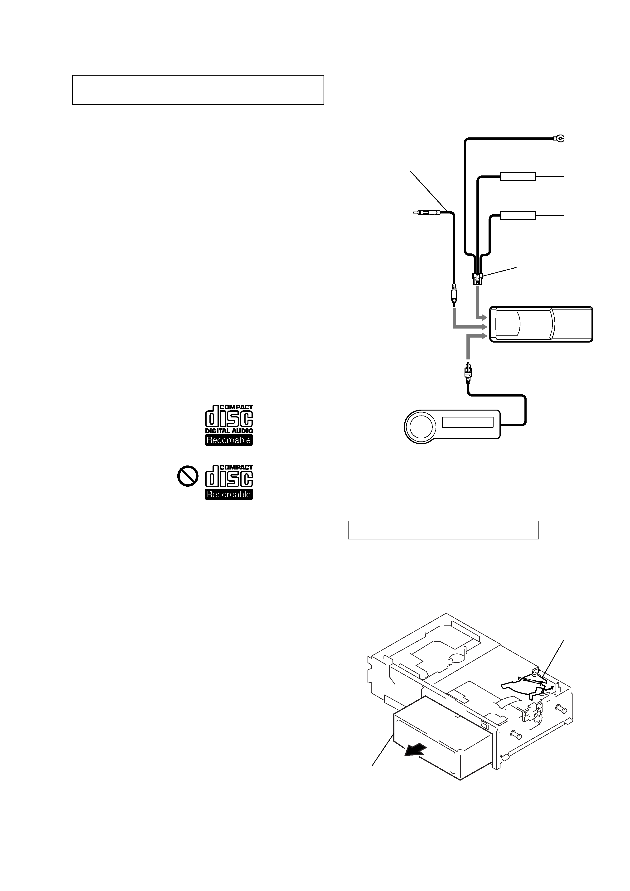
DISC MAGAZINE GETTING OUT PROCEDURE
ON THE POWER SUPPLY IS OFF
Remove the CASE (LOWER. T) beforehand
1) Press the lever (ML.S) assy in the direction of arrow A.
2) Removal the magazine assy.
Note: Take out the magazine only when the tray is completely within the
magazine. If the disk or tray is sticking out, turn on the power and
eject the magazine.
Lever (ML.S)
Magazine assy
A
Notes on CD-R/CD-RW discs
You can play CD-Rs (recordable CDs)
designed for audio use on this unit.
Look for this mark to
distinguishCD-Rs for audio use.
This mark denotes that a disc is not for audio
use.
Some CD-Rs (depending on
the equipment used for its recording or the
condition of the disc) may not play on this
unit.
You cannot play a CD-R that is not
finalized*.
You cannot play CD-RWs (rewritable CDs).
* A process necessary for a recorded CD-R disc to
be played on the audio CD player.
power supply cord
(J-2502-058-2)
compact disc changer
RF output cord
(J-2502-058-1)
wired remote commander
JIG ON REPAIRING
When repairing this set, connect the jig (cord) for RF output ex-
tract (Part No. J-2502-058-1) and power supply (Part No. J-2502-
058-2) as the figure shown below.
Ver 1.1
4
CDX-555RF/555XRF
SECTION 2
GENERAL
This section is extracted from
instruction manual.
12
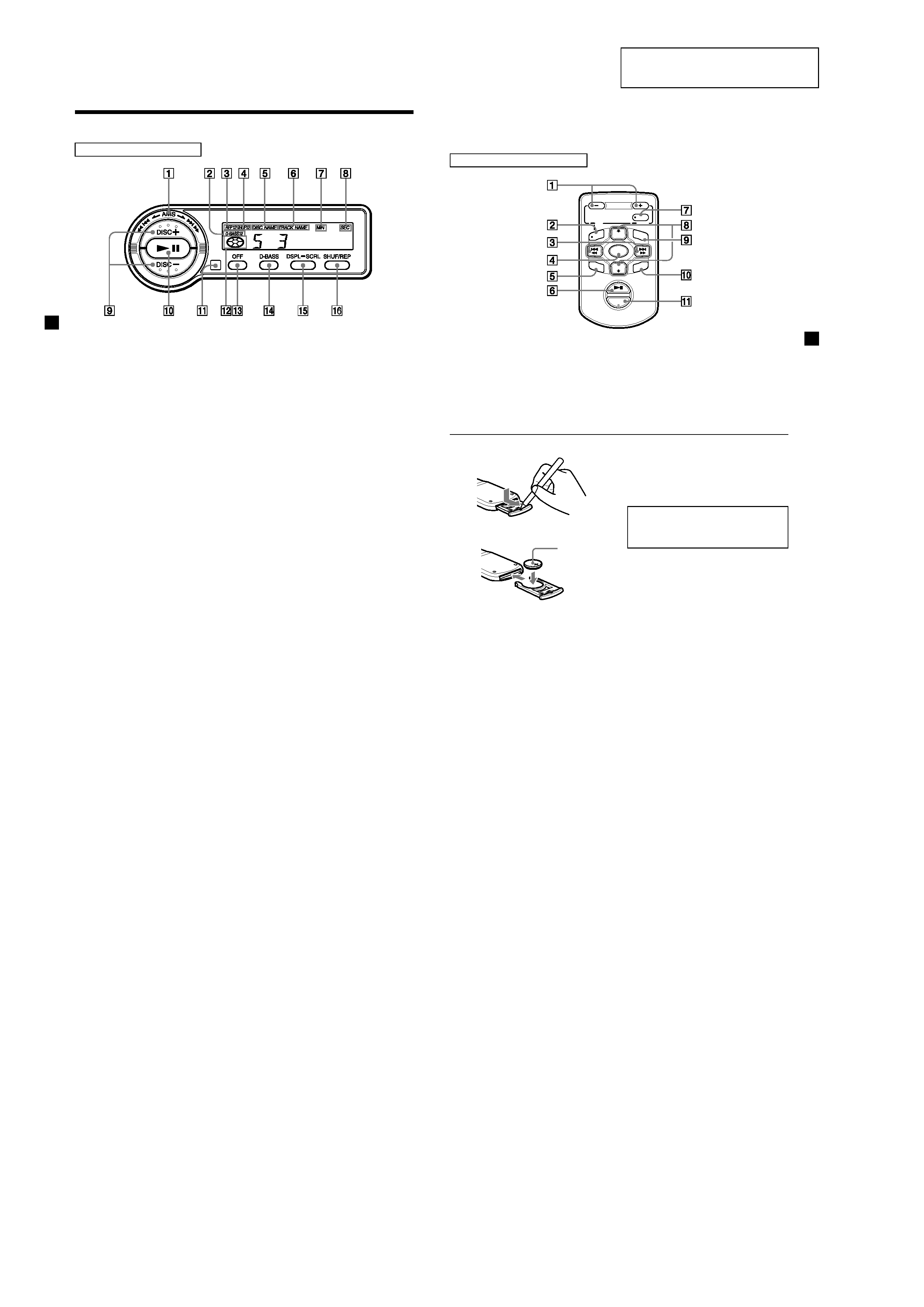
Location of controls
Wired remote (RM-X80RF)
Refer to the pages for details.
1
AMS (Automatic Music Sensor/manual
search) control 6, 7
2
D-BASS indication 9
3
REP (repeat play) indication
4
SHUF (shuffle play) indication
5
DISC NAME (disc number/disc name)
indication
The indicated disc number matches the
disc number in the disc magazine.
6
TRACK NAME (track number/track
name) indication
7
MIN (minute) indication
8
SEC (second) indication
9
DISC (disc select) buttons 6, 7, 9
0
u (play/pause) button 6
If pressed during CD playback, the CD
will pause. If pressed again, CD playback
will continue.
qa
Infrared receptor for the wireless
remote
qs
Play/pause indication
Turns around during CD playback and
flashes when the pause button is pressed.
qd
OFF button 6
qf
D-BASS button 9
qg
DSPL-SCRL (indication change/name
scroll) button 8
qh
SHUF/REP (shuffle play/repeat play/
control mode set) button 6, 7, 9
13
Wireless remote (RM-X81RF)
1
NAME (character select) buttons 8
2
DSPL/-EDIT (display/name edit) button
8
3
AMS/MANU (Automatic Music Sensor/
manual search) buttons
4
D-BASS button 9
5
REP (repeat play) button 7
6
u (play/pause) button 6
7
ENTER/-DELETE button 8
8
DISC (disc select) buttons 6, 7, 9
9
SCRL (scroll) button
0
SHUF (shuffle play) button 6, 7, 9
qa
OFF button 6
Lithium battery life
When the battery becomes weak, you will not
be able to operate the unit with the wireless
remote.
Battery life is approx. six months depending
on the conditions of use.
WARNING
Battery may explode if mistreated.
Do not recharge, disassemble or dispose of
in fire.
Notes on the lithium battery
· Keep the lithium battery out of the reach of
children.
Should the battery be swallowed,
immediately consult a doctor.
· Wipe the battery with a dry cloth to assure a
good contact.
· Be sure to observe the correct polarity when
installing the battery.
· Do not hold the battery with metallic
tweezers, otherwise a short circuit may
occur.
+ side up
x
Installing the battery
Replace the battery with a Sony CR2025 or
Duracell DL-2025 lithium battery. Use of
another battery may present a risk of fire or
explosion.
OFF
DISC
D--BASS
NAME
EDIT
DELETE
DISC +
REP
SHUF
DSPL
SCRL
ENTER
5
CDX-555RF/555XRF
Note
The supplied wireless remote (RM-X81RF) can be operated almost like
the wired remote (RM-X80RF).
Changement de la fréquence de transmission
Comme cet appareil traite le son de lecture CD via un syntoniseur
FM, il se peut qu'il y ait des interférences durant la lecture du CD. En
pareil cas, changez la fréquence du signal RF modulé transmis par
l'appareil. Le réglage initial est de 88,3 MHz.
1 Appuyez sur
(SHUF/REP) pendant deux secondes jusqu'à ce
que la fréquence apparaisse.
2 Appuyez plusieurs fois de suite sur
ou
pour
sélectionner la fréquence.
Chaque fois que vous appuyez sur
ou
, la
fréquence change dans l'ordre suivant :
: 88.3 MHz
t 89.9 MHz t 89.7 MHz t 89.5 MHz t
89.3 MHz
t 89.1 MHz t 88.9 MHz t 88.7 MHz t
88.5 MHz
t 88.3 MHz
:88.3 MHz
t 88.5 MHz t 88.7 MHz t 88.9 MHz t
89.1 MHz
t 89.3 MHz t 89.5 MHz t 89.7 MHz t
89.9 MHz
t 88.3 MHz
3 Appuyez sur
(SHUF/REP) pendant deux secondes.
Utilisation de la télécommande sans fil
1 Appuyez sur
(SHUF) pendant deux secondes jusqu'à ce que la
fréquence apparaisse.
2 Appuyez plusieurs fois de suite sur
ou
pour
sélectionner la fréquence.
3 Appuyez sur
(SHUF) pendant deux secondes.
Remarques
· Si vous changez la fréquence de transmission de l'appareil, n'oubliez pas
de syntoniser votre syntoniseur FM sur la nouvelle fréquence
sélectionnée.
· Appuyez sur la touche
u de la télécommande filaire avant de changer
la fréquence si l'appareil n'est pas sous tension.
Changement du niveau de sortie
Vous pouvez sélectionner le niveau de sortie de l'appareil. En
principe, l'appareil est utilisé au niveau de sortie initial ; changez le
niveau si nécessaire.
1 Appuyez sur
(SHUF/REP) pendant deux secondes.
2 Appuyez brièvement sur
(SHUF/REP).
3 Appuyez plusieurs fois de suite sur
ou
pour
sélectionner le niveau de sortie.
Pour diminuer le niveau de sortie
Pour augmenter le niveau de sortie
4 Appuyez sur
(SHUF/REP) pendant deux secondes.
Utilisation de la télécommande sans fil
1 Appuyez sur
(SHUF) pendant deux secondes.
2 Appuyez de nouveau brièvement sur
(SHUF).
3 Appuyez sur
ou
pour sélectionner le niveau
de sortie.
4 Appuyez sur
(SHUF) pendant deux secondes.
Remarque
Si vous sélectionnez le niveau 4 ou 5, le son de lecture CD peut comporter
des distorsions ou des parasites. En pareil cas, sélectionnez un niveau de
sortie inférieur et baissez le volume de votre autoradio.
Remarque
La télécommande sans fil fournie (RM-X81RF) se manipule
pratiquement comme la télécommande filaire (RM-X80RF).
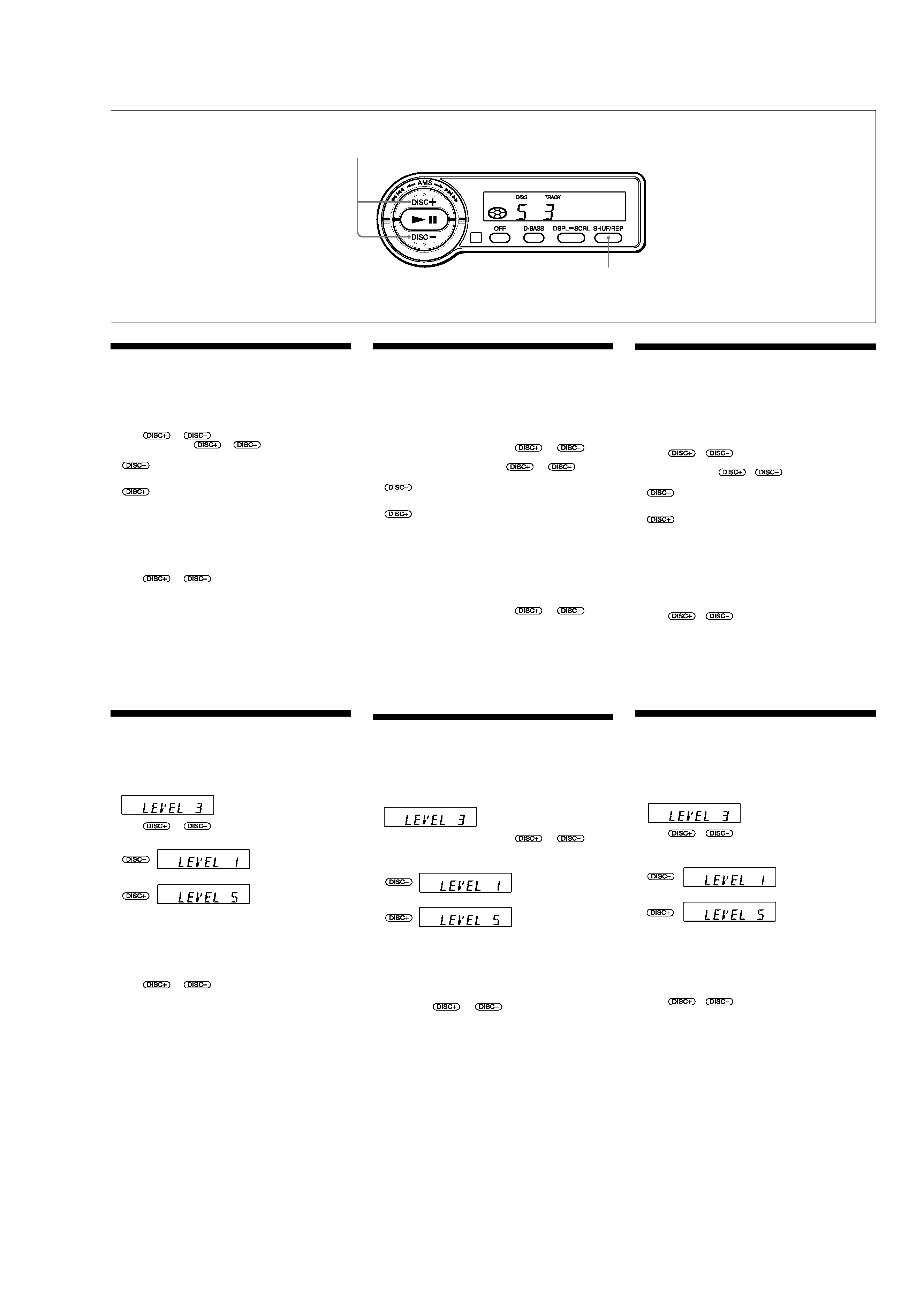
Changing the transmitting frequency
Because this unit processes CD playback sound through an FM
tuner, there may be interference noise during CD playback. In such a
case, change the frequency of the modulated RF signal transmitted
from the unit. The initial setting is 88.3 MHz.
1 Press
(SHUF/REP) for two seconds until frequency appears.
2 Press
or
repeatedly to select the frequency.
Each time you press
or
, the frequency changes
as follows:
: 88.3 MHz
t 89.9 MHz t 89.7 MHz t 89.5 MHz t
89.3 MHz
t 89.1 MHz t 88.9 MHz t 88.7 MHz t
88.5 MHz
t 88.3 MHz
:88.3 MHz
t 88.5 MHz t 88.7 MHz t 88.9 MHz t
89.1 MHz
t 89.3 MHz t 89.5 MHz t 89.7 MHz t
89.9 MHz
t 88.3 MHz
3 Press
(SHUF/REP) for two seconds.
Using on the wireless remote
1 Press
(SHUF) for two seconds until frequency appears.
2 Press
or
repeatedly to select the frequency.
3 Press
(SHUF) for two seconds.
Notes
· When you change the transmitting frequency on the unit, be sure to
tune your FM tuner to the newly selected one.
· Press
u on the wired remote before changing the frequency if the
power to the unit is turned off.
Changing the Output Level
You can select the output level of the unit. Normally the unit is used
in the initial output level; change the level if necessary.
1 Press
(SHUF/REP) for two seconds.
2 Press
(SHUF/REP) momentarily.
3 Press
or
repeatedly to select the output level.
To decrease the output level
To increase the output level
4 Press
(SHUF/REP) for two seconds.
Using on the wireless remote
1 Press
(SHUF) for two seconds.
2 Press
(SHUF) again momentarily.
3 Press
or
to select the output level.
4 Press
(SHUF) for two seconds.
Note
When you select level 4 or 5, the CD playback sound may be distorted or
you may hear some noise. In such a case, select a lower output level on the
unit and turn down the overall volume on your car audio.
:
:
Initial setting
SHUF/REP
Réglage initial
:
:
:
:
DISC +/
Wired remote (RM-X80RF)/Télécommande à fil (RM-X80RF)/Mando a distancia alámbrico (RM-X80RF)
Nota
El mando a distancia inalámbrico suministrado (RM-X81RF) puede
utilizarse casi como el mando a distancia alámbrico (RM-X80RF).
Cambio de la frecuencia de transmisión
Puesto que esta unidad procesa el sonido de reproducción de CD
mediante un sintonizador de FM, es posible que se oiga ruido
producio por interferencias durante la reproducción de CD. En tal
caso, cambie la frecuencia de la señal RF modulada que transmite el
sistema. El ajuste inicial es 88,3 MHz.
1 Pulse
(SHUF/REP) durante dos segundos hasta que aparezca
la frecuencia.
2 Pulse
o
varias veces para seleccionar la
frecuencia.
Cada vez que pulse
o
, la frecuencia cambiará de
la siguiente forma:
: 88,3 MHz
t 89,9 MHz t 89,7 MHz t 89,5 MHz t
89,3 MHz
t 89,1 MHz t 88,9 MHz t 88,7 MHz t
88,5 MHz
t 88,3 MHz
:88,3 MHz
t 88,5 MHz t 88,7 MHz t 88,9 MHz t
89,1 MHz
t 89,3 MHz t 89,5 MHz t 89,7 MHz t
89,9 MHz
t 88,3 MHz
3 Pulse
(SHUF/REP) durante dos segundos.
Uso con el mando a distancia inalámbrico
1 Pulse
(SHUF) durante dos segundos hasta que aparezca la
frecuencia.
2 Pulse
o
varias veces para seleccionar la
frecuencia.
3 Pulse
(SHUF) durante dos segundos.
Notas
· Cuando cambie la frecuencia de transmisión de la unidad, asegúrese de
ajustar el sintonizador de FM en la frecuencia seleccionada.
· Pulse
u en el mando alámbrico antes de cambiar la frecuencia si la
alimentación de la unidad está desactivada.
Cambio del nivel de salida
Es posible seleccionar el nivel de salida de la unidad. Normalmente
la unidad se utiliza con el nivel de salida inicial. Cámbielo si es
necesario.
1 Pulse
(SHUF/REP) durante dos segundos.
2 Pulse
(SHUF/REP) durante un instante.
3 Pulse
o
varias veces para seleccionar el nivel
de salida.
Para reducir el nivel de salida
Para aumentar el nivel de salida
4 Pulse
(SHUF/REP) durante dos segundos.
Uso con el mando a distancia inalámbrico
1 Pulse
(SHUF) durante dos segundos.
2 Vuelva a pulsar
(SHUF) momentáneamente.
3 Pulse
o
para seleccionar el nivel de salida.
4 Pulse
(SHUF) durante dos segundos.
Nota
Si selecciona el nivel 4 ó 5, es posible que el sonido de reproducción de CD
se distorsione o que se oiga cierto ruido. En tal caso, seleccione un nivel de
salida inferior en la unidad y disminuya el volumen general en el sistema
de audio del automóvil.
Ajuste inicial