SERVICE MANUAL
COMPACT DISC CHANGER SYSTEM
US Model
Canadian Model
CDX-454RF
E Model
CDX-454XRF
SPECIFICATIONS
CDX-454RF/454XRF
Photo: CDX-454RF
Ver 1.1 2002.03
9-873-373-02
Sony Corporation
2002C0500-1
e Vehicle Company
C
2002.03
Published by Sony Engineering Corporation
Model Name Using Similar Mechanism
CDX-444RF
CD Drive Mechanism Type
MG-251A-137
Optical Pick-up Name
KSS-720A
CD changer
System
Compact disc digital audio system
Transmitting
Laser Diode Properties
Material
GaAlAs
Wavelength
780 nm
Emission Duration
Continuous
Laser output power
Less than 44.6 µW*
*
This output is the value measured at a distance of 200 mm from the
objective lens surface on the Optical Pick-up Block.
frequency
88.3 MHz/88.5 MHz/
88.7 MHz/88.9 MHz/
89.1 MHz/89.3 MHz/
89.5 MHz/89.7 MHz/
89.9 MHz (switchable)
Input/output terminals
Wired remote control
(8 pin)
RF signal (FM) output
Power input (3 pin)
Current drain
800 mA (at playback)
800 mA (at disc loading/
ejecting)
Operating temperature
10°C to +55°C
(14°F to 131°F)
Dimensions
Approx. 262
× 90 ×
185 mm
(10 3/8
× 3 5/8 × 7 3/8 in.)
(w/h/d)
Mass
Approx. 2.1 kg (4 lb. 10 oz.)
Relay box
Input/output
Aerial input terminal
Aerial output cord
CD changer input cord
Dimensions
Approx. 40
× 40 × 27 mm
(1 5/8
× 1 5/8 × 1 1/8 in.)
(w/h/d)
Mass
Approx. 140 g (5 oz.)
Wired remote (RM-X82RF)
Dimensions
Approx. 122
× 36.5 ×
15.5 mm
(4 7/8
× 1 7/16 × 5/8 in.)
(w/h/d)
Mass
Approx. 255 g (9 oz.)
General
Supplied accessories
Disc magazine (1)
Parts for installation and
connections (1 set)
Design and specifications are subject to change
without notice.
2
CDX-454RF/454XRF
TABLE OF CONTENTS
1.
SERVICING NOTES ................................................ 3
2.
GENERAL
Location of controls ........................................................
4
Installation .......................................................................
5
Connections .....................................................................
7
3.
DISASSEMBLY
3-1. Disassembly Flow ..........................................................
8
3-2. Case (Upper. T), Front Panel Assy .................................
9
3-3. Mechanism Deck (MG-251A-137) ................................
9
3-4. FM Board ........................................................................ 10
3-5. MAIN Board, Slide Variable Resistor
(Elevator Height Sensor) (RV202) ................................. 10
3-6. ELJ Motor Assy (Elevator) (M104) ................................ 11
3-7. Escutcheon (T) ................................................................ 11
3-8. Chassis (U.S) Sub Assy .................................................. 12
3-9. Chassis assy ..................................................................... 12
3-10. RF Board ......................................................................... 13
3-11. Sled Motor Assy (251) (M101),
Optical Pick-up (KSS-720A) .......................................... 13
3-12. LSW Board, Spindle Motor (S) Sub Assy (M102) ........ 14
3-13. ELJ Motor Assy (Chucking) (M103) ............................. 14
4.
ASSEMBLY
4-1. Assembly Flow ................................................................ 15
4-2. Optical Pick-up Complete Assy ...................................... 15
4-3. Gear (Lomini)/(Load 1) Assy ......................................... 16
4-4. Operation Check ............................................................. 16
5.
MECHANICAL ADJUSTMENTS ....................... 17
6.
ELECTRICAL CHECK .......................................... 18
7.
DIAGRAMS
7-1. Block Diagram SERVO Section .............................. 21
7-2. Block Diagram MAIN Section ................................ 22
7-3. Note for Printed Wiring Boards and
Schematic Diagrams ....................................................... 23
7-4. Printed Wiring Boards RF/LSW Boards ................. 24
7-5. Schematic Diagram RF/LSW Boards ...................... 25
7-6. Printed Wiring Board
MAIN Board (Component Side) .............................. 26
7-7. Printed Wiring Boards
MAIN (Conductor Side)/SW Boards ....................... 27
7-8. Schematic Diagram MAIN Board (1/2) .................. 28
7-9. Schematic Diagram MAIN (2/2)/SW Boards ......... 29
7-10. Printed Wiring Board FM Board ............................. 30
7-11. Schematic Diagram FM Board ................................. 31
7-12. IC Pin Function Description ........................................... 36
8.
EXPLODED VIEWS
8-1. General Section-1 ............................................................ 38
8-2. General Section-2 ............................................................ 39
8-3. Mechanism Deck Section-1 (MG-251A-137) ................ 40
8-4. Mechanism Deck Section-2 (MG-251A-137) ................ 41
8-5. Mechanism Deck Section-3 (MG-251A-137) ................ 42
8-6. Mechanism Deck Section-4 (MG-251A-137) ................ 43
9.
ELECTRICAL PARTS LIST ............................... 44
ATTENTION AU COMPOSANT AYANT RAPPORT
À LA SÉCURITÉ!
LES COMPOSANTS IDENTIFIÉS PAR UNE MARQUE 0
SUR LES DIAGRAMMES SCHÉMATIQUES ET LA LISTE
DES PIÈCES SONT CRITIQUES POUR LA SÉCURITÉ
DE FONCTIONNEMENT. NE REMPLACER CES COM-
POSANTS QUE PAR DES PIÈCES SONY DONT LES
NUMÉROS SONT DONNÉS DANS CE MANUEL OU
DANS LES SUPPLÉMENTS PUBLIÉS PAR SONY.
SAFETY-RELATED COMPONENT WARNING!!
COMPONENTS IDENTIFIED BY MARK 0 OR DOTTED
LINE WITH MARK 0 ON THE SCHEMATIC DIAGRAMS
AND IN THE PARTS LIST ARE CRITICAL TO SAFE
OPERATION. REPLACE THESE COMPONENTS WITH
SONY PARTS WHOSE PART NUMBERS APPEAR AS
SHOWN IN THIS MANUAL OR IN SUPPLEMENTS PUB-
LISHED BY SONY.
CAUTION
Use of controls or adjustments or performance of procedures
other than those specified herein may result in hazardous ra-
diation exposure.
Notes on chip component replacement
· Never reuse a disconnected chip component.
· Notice that the minus side of a tantalum capacitor may be dam-
aged by heat.
Flexible Circuit Board Repairing
· Keep the temperature of the soldering iron around 270 °C dur-
ing repairing.
· Do not touch the soldering iron on the same conductor of the
circuit board (within 3 times).
· Be careful not to apply force on the conductor when soldering
or unsoldering.
OPTICAL
PICK-UP
BLOCK
SEMI-FIXED
RESISTOR
US/Canadian model:
If the optical pick-up block is defective, please replace the whole
optical pick-up block.
Never turn the semi-fixed resistor located at the side of optical
pick-up block.
3
CDX-454RF/454XRF
SECTION 1
SERVICING NOTES
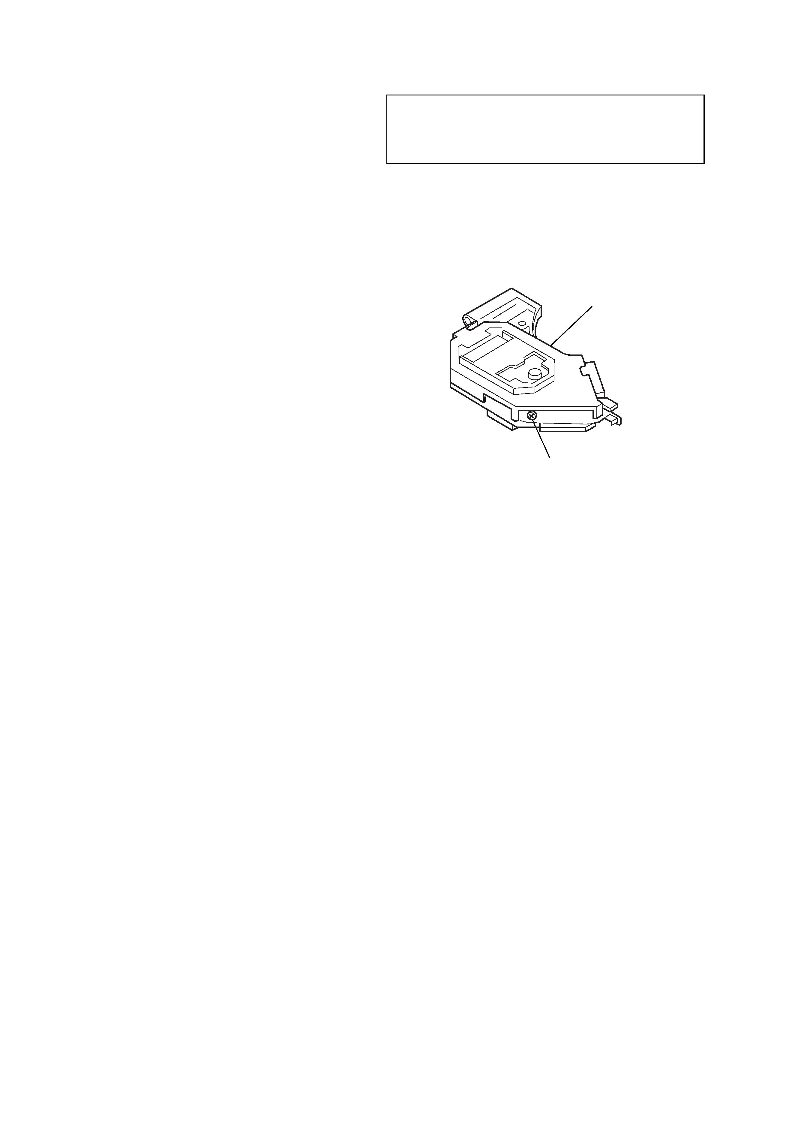
DISC MAGAZINE GETTING OUT PROCEDURE
ON THE POWER SUPPLY IS OFF
Remove the COVER (LOWER.T) assy beforehand
1) Press the lever (ML.S) to arrow direction.
2) Removal the magazine assy.
Note: Take out the magazine only when the tray is completely within the
magazine. If the disk or tray is sticking out, turn on the power and
eject the magazine.
NOTES ON HANDLING THE OPTICAL PICK-
UP BLOCK OR BASE UNIT
Lever (ML.S)
Magazine assy
The laser diode in the optical pick-up block may suffer electro-
static breakdown because of the potential difference generated by
the charged electrostatic load, etc. on clothing and the human body.
During repair, pay attention to electrostatic breakdown and also
use the procedure in the printed matter which is included in the
repair parts.
The flexible board is easily damaged and should be handled with
care.
NOTES ON LASER DIODE EMISSION CHECK
The laser beam on this model is concentrated so as to be focused
on the disc reflective surface by the objective lens in the optical
pick-up block. Therefore, when checking the laser diode emis-
sion, observe from more than 30 cm away from the objective lens.
TEST DISC
This set can playback a CD-R, CD-RW for audio use. When test
this set, use the following test disc.
Test disc for CD-R: TCD-R082LMT (Part No.: J-2502-063-1)
Notes on CD-R/CD-RW discs
You can play CD-Rs (recordable CDs)
designed for audio use on this unit.
Look for this mark to
distinguish CD-Rs for audio
use.
This mark denotes that a
disc is not for audio use.
Some CD-Rs (depending on the equipment
used for its recording or the condition of
the disc) may not play on this unit.
You cannot play a CD-R that is not
finalized*.
You cannot play CD-RWs (rewritable CDs).
* A process necessary for a recorded CD-R disc to
be played on the audio CD player.
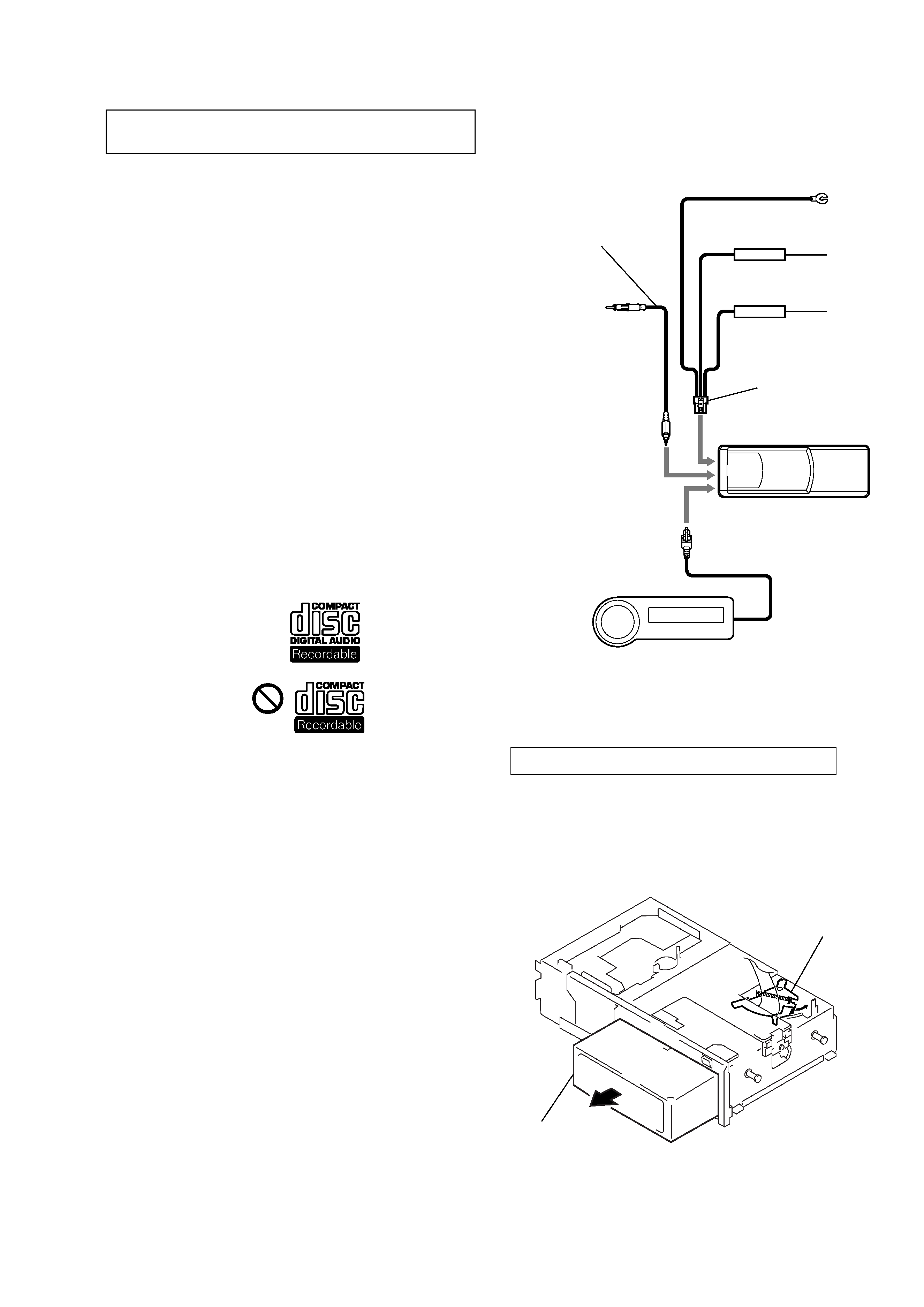
power supply cord
(J-2502-058-2)
compact disc changer
RF output cord
(J-2502-058-1)
wirerd remote commander
JIG ON REPAIRING
When repairing this set, connect the jig (cord) for RF output ex-
tract (Part No. J-2502-058-1) and power supply (Part No. J-2502-
058-2) as the figure shown below.
Ver 1.1
4
CDX-454RF/454XRF
SECTION 2
GENERAL
This section is extracted from
instruction manual.
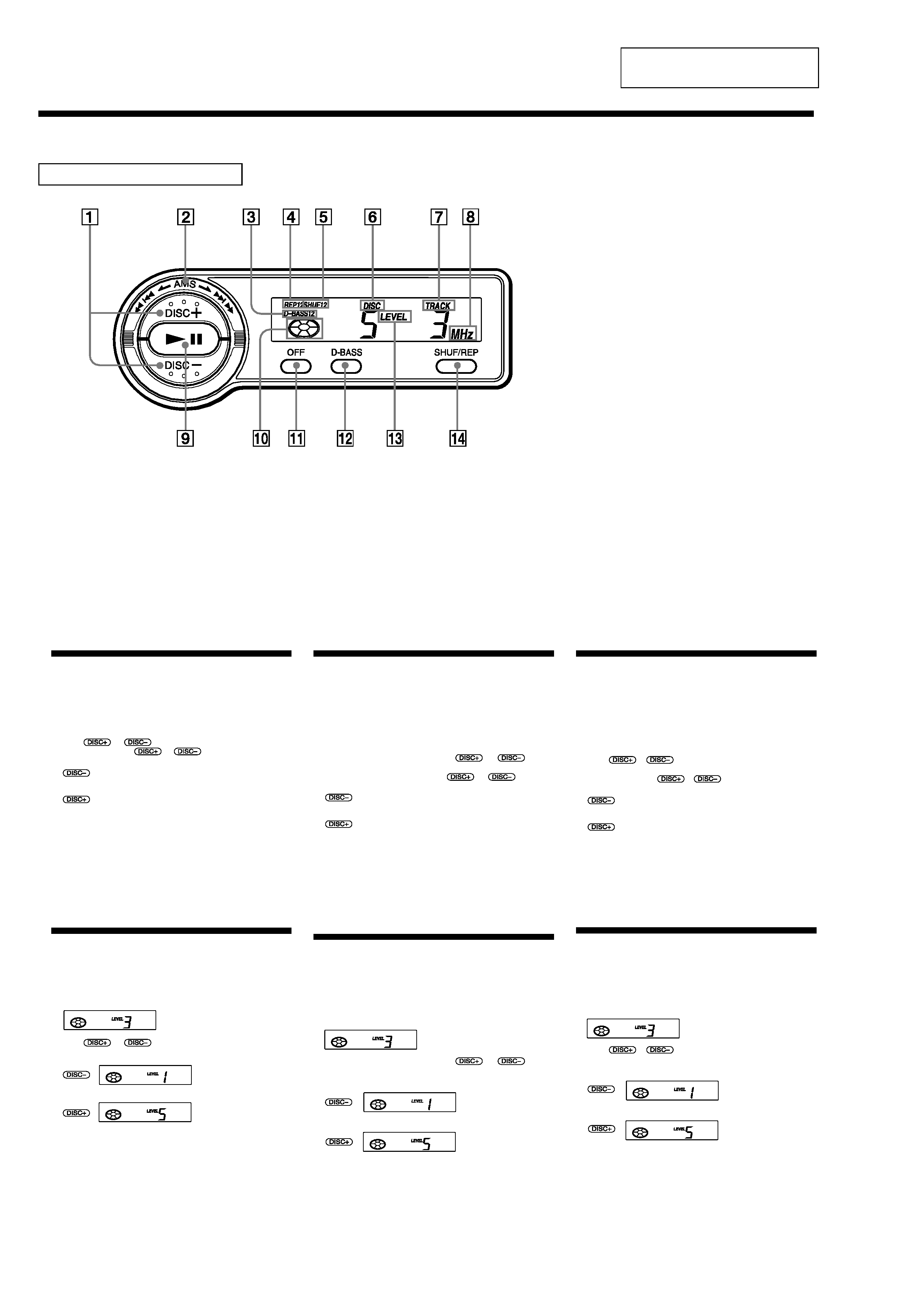
Location of controls
Wired remote (RM-X82RF)
Refer to the pages for details.
1
DISC (disc select) buttons 5, 6, 8
2
AMS (Automatic Music Sensor/manual
search) control 6
3
D-BASS indication 7
4
REP (repeat play) indication
5
SHUF (shuffle play) indication
6
DISC (disc number) indication
The indicated disc number matches the
disc number in the disc magazine.
7
TRACK (track number) indication
8
MHz (frequency) indication
9
u
(play/pause) button 5, 6
If pressed during CD playback, the CD
will pause. If pressed again, CD playback
will continue.
0
Play/pause indication
Turns around during CD playback and
flashes when the pause button is pressed.
qa
OFF button 6
qs
D-BASS button 7
qd
LEVEL (output level) indication
qf
SHUF/REP (shuffle play/repeat play/
control mode set) button 5, 7, 8
Changing the transmitting frequency
Because this unit processes CD playback sound through an FM
tuner, there may be interference noise during CD playback. In such a
case, change the frequency of the modulated RF signal transmitted
from the unit. The initial setting is 88.3 MHz.
1 Press (SHUF/REP) for two seconds until frequency appears.
2 Press
or
repeatedly to select the frequency.
Each time you press
or
, the frequency changes
as follows:
: 88.3 MHz t 89.9 MHz t 89.7 MHz t 89.5 MHz t
89.3 MHz t 89.1 MHz t 88.9 MHz t 88.7 MHz t
88.5 MHz t 88.3 MHz
: 88.3 MHz t 88.5 MHz t 88.7 MHz t 88.9 MHz t
89.1 MHz t 89.3 MHz t 89.5 MHz t 89.7 MHz t
89.9 MHz t 88.3 MHz
3 Press (SHUF/REP) for two seconds.
Notes
· When you change the transmitting frequency on the unit, be sure to
tune your FM tuner to the newly selected one.
· Press u on the wired remote before changing the frequency if the
power to the unit is turned off.
Changing the Output Level
You can select the output level of the unit. Normally the unit is used
in the initial output level; change the level if necessary.
1 Press (SHUF/REP) for two seconds.
2 Press (SHUF/REP) momentarily.
3 Press
or
repeatedly to select the output level.
To decrease the output level
To increase the output level
4 Press (SHUF/REP) for two seconds.
Note
When you select level 4 or 5, the CD playback sound may be distorted or
you may hear some noise. In such a case, select a lower output level on the
unit and turn down the overall volume on your car audio.
Changement de la frquence de transmission
Comme cet appareil traite le son de lecture CD via un syntoniseur
FM, il se peut qu'il y ait des interférences durant la lecture du CD. En
pareil cas, changez la fréquence du signal RF modulé transmis par
l'appareil. Le réglage initial est de 88,3 MHz.
1 Appuyez sur (SHUF/REP) pendant deux secondes jusqu'à ce
que la fréquence apparaisse.
2 Appuyez plusieurs fois de suite sur
ou
pour
sélectionner la fréquence.
Chaque fois que vous appuyez sur
ou
, la
fréquence change dans l'ordre suivant :
: 88.3 MHz t 89.9 MHz t 89.7 MHz t 89.5 MHz t
89.3 MHz t 89.1 MHz t 88.9 MHz t 88.7 MHz t
88.5 MHz t 88.3 MHz
: 88.3 MHz t 88.5 MHz t 88.7 MHz t 88.9 MHz t
89.1 MHz t 89.3 MHz t 89.5 MHz t 89.7 MHz t
89.9 MHz t 88.3 MHz
3 Appuyez sur (SHUF/REP) pendant deux secondes.
Remarques
· Si vous changez la fréquence de transmission de l'appareil, n'oubliez pas
de syntoniser votre syntoniseur FM sur la nouvelle fréquence
sélectionnée.
· Appuyez sur la touche u de la télécommande filaire avant de changer
la fréquence si l'appareil n'est pas sous tension.
Changement du niveau de sortie
Vous pouvez sélectionner le niveau de sortie de l'appareil. En
principe, l'appareil est utilisé au niveau de sortie initial ; changez le
niveau si nécessaire.
1 Appuyez sur (SHUF/REP) pendant deux secondes.
2 Appuyez brièvement sur (SHUF/REP).
3 Appuyez plusieurs fois de suite sur
ou
pour
sélectionner le niveau de sortie.
Pour diminuer le niveau de sortie
Pour augmenter le niveau de sortie
4 Appuyez sur (SHUF/REP) pendant deux secondes.
Remarque
Si vous sélectionnez le niveau 4 ou 5, le son de lecture CD peut comporter
des distorsions ou des parasites. En pareil cas, sélectionnez un niveau de
sortie inférieure et baissez le volume de votre autoradio.
:
:
Initial setting
:
:
Ajuste inicial
Cambio de la frecuencia de transmisin
Puesto que esta unidad procesa el sonido de reproducción de CD
mediante un sintonizador de FM, es posible que se oiga ruido
producido por interferencias durante la reproducción de CD. En tal
caso, cambie la frecuencia de la señal RF modulada que transmite el
sistema. El ajuste inicial es 88,3 MHz.
1 Pulse (SHUF/REP) durante dos segundos hasta que aparezca
la frecuencia.
2 Pulse
o
varias veces para seleccionar la
frecuencia.
Cada vez que pulse
o
, la frecuencia cambiará de
la siguiente forma:
: 88,3 MHz t 89,9 MHz t 89,7 MHz t 89,5 MHz t
89,3 MHz t 89,1 MHz t 88,9 MHz t 88,7 MHz t
88,5 MHz t 88,3 MHz
: 88,3 MHz t 88,5 MHz t 88,7 MHz t 88,9 MHz t
89,1 MHz t 89,3 MHz t 89,5 MHz t 89,7 MHz t
89,9 MHz t 88,3 MHz
3 Pulse (SHUF/REP) durante dos segundos.
Nota
· Cuando cambie la frecuencia de transmisión de la unidad, asegúrese de
ajustar el sintonizador de FM en la frecuencia seleccionada.
· Pulse u en el mando alámbrico antes de cambiar la frecuencia si la
alimentación del sistema está desactivada.
Cambio del nivel de salida
Es posible seleccionar el nivel de salida del sistema. Normalmente el
sistema se utiliza con el nivel de salida inicial. Cámbielo si es
necesario.
1 Pulse (SHUF/REP) durante dos segundos.
2 Pulse (SHUF/REP) momentáneamente.
3 Pulse
o
varias veces para seleccionar el nivel
de salida.
Para reducir el nivel de salida
Para aumentar el nivel de salida
4 Pulse (SHUF/REP) durante dos segundos.
Nota
Si selecciona el nivel 4 ó 5, es posible que el sonido de reproducción de CD
se distorsione o que se oiga cierto ruido. En tal caso, seleccione un nivel de
salida inferior en la unidad y disminuya el volumen general en el sistema
de audio del automóvil.
:
:
Réglage initial
5
CDX-454RF/454XRF
2
3
1
1
2
3
¿ 3.5 mm
(5/32 in.)
¿ 3,5 mm
(5/32 po.)
¿ 3,5 mm
CD changer
·Choose the mounting location carefully, observing the following:
-- Do not install the unit where;
·the ambient temperature exceeds 55°C (131°F).
·it will be exposed to direct sunlight or hot air from a heater.
·it will be exposed to rain, water, or high humidity.
·it will be exposed to a lot of dust.
·it will be subject to excessive vibration.
-- The fuel tank should not be damaged by the tapping screws.
-- There should be no wire harnesses or pipelines under the place
where you are going to install the unit.
-- The spare tire, tools, or other equipment in or under the trunk
should not be interfered with or damaged by the screws or the
unit itself.
Notes
· Be sure to use only the supplied mounting hardware for a safe and
secure installation.
· Make holes of ¿ 3.5 mm (5/32 in.) only after making sure there is nothing
on the other side of the mounting surface.
How to install the CD changer
·When you install the CD changer, be careful not to damage wiring
or equipment on the other side of the mounting surface.
·The brackets 1 provide two positions for mounting, high and low.
Use the appropriate screw holes according to your preference.
Cambiador de discos compactos
·Elija cuidadosamente el lugar de montaje teniendo en cuenta lo
siguiente:
-- No instale la unidad donde:
·la temperatura ambiente sea superior a 55°C.
·quede expuesta a la luz solar directa o al aire caliente de un
calefactor.
·quede expuesta a lluvia, agua o mucha humedad.
·quede expuesta a polvo excesivo.
·quede sujeta a vibraciones excesivas.
-- El depósito de combustible no deberá dañarse con los tornillos
autorroscantes.
-- No deberá haber cables ni tubos debajo del lugar en el que vaya
a instalar la unidad.
-- Ni los tornillos ni la propia unidad deberían dañar ni interferir
con la rueda de repuesto, las herramientas y demás equipos del
portaequipajes o situados debajo de éste.
Notas
· Para realizar una instalación firme y segura, cerciórese de utilizar
solamente la ferretería de montaje suministrada.
· Antes de hacer los orificios de ¿ 3,5 mm, compruebe que no haya nada
en el otro lado de la superficie de montaje.
Forma de instalar el cambiador de discos
compactos
·Cuando instale el cambiador de discos compactos, cerciórese de no
dañar el cableado ni los equipos que puedan encontrarse en la otra
parte de la superficie de montaje.
·Los soportes 1 proporcionan dos posiciones de montaje, alta y
baja. Utilice los orificios para tornillo apropiados según sus
preferencias.
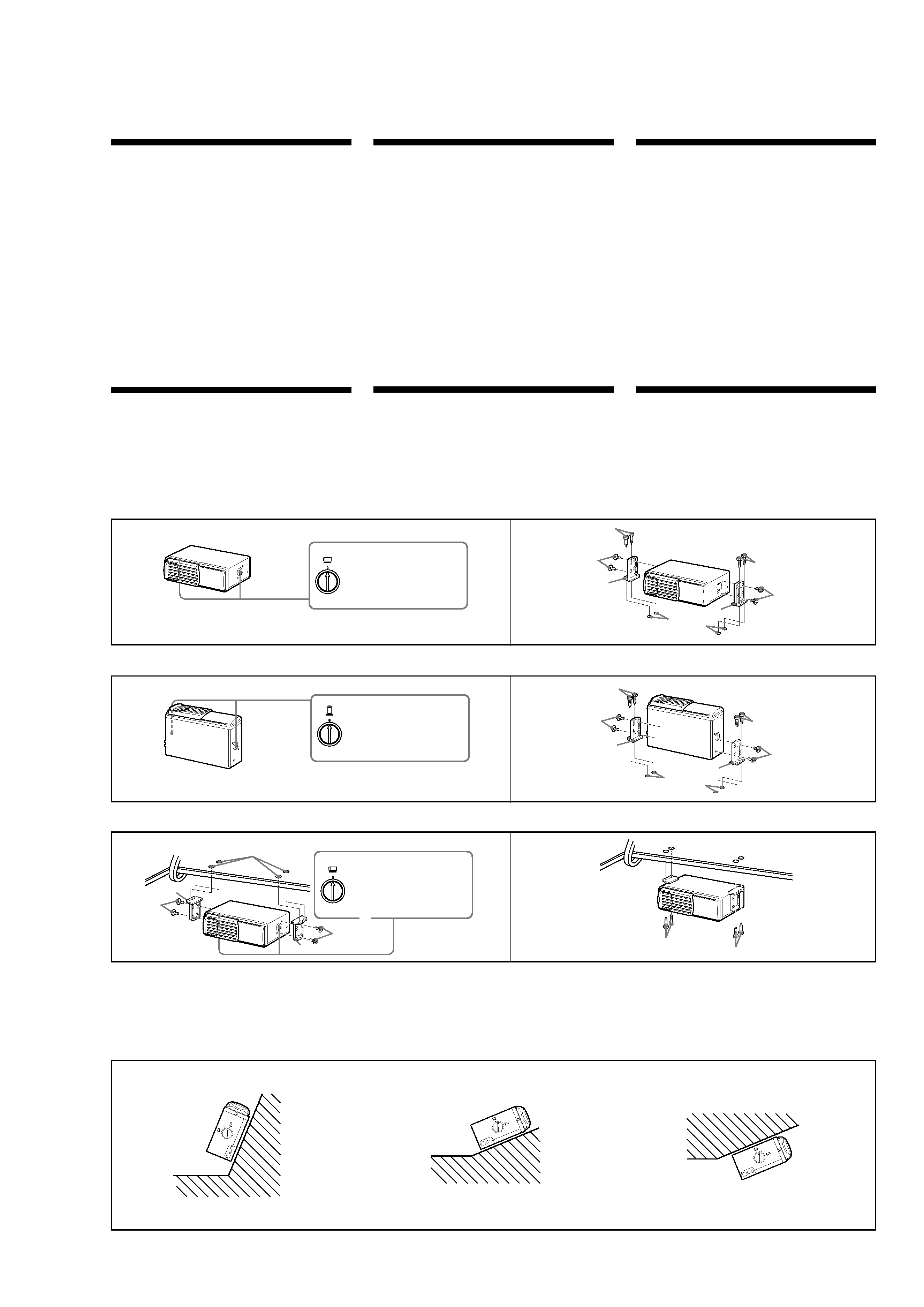
Instalaci n horizontal
1
Vertical installation
Installation verticale
1
2
Suspended installation
Installation suspendue
1
2
When the unit is to be installed under the rear tray or in the trunk,
observe the following.
·Choose the mounting location carefully so that the unit can be
installed horizontally.
·Make sure the unit does not hinder the action of the torsion bar
spring, hinge, etc. of the deck lid.
Cuando vaya a instalar la unidad debajo de la bandeja trasera o en el
portaequipajes, tenga en cuenta lo siguiente.
·Elija cuidadosamente el lugar de montaje de forma que la unidad
pueda instalarse horizontalmente.
·Asegúrese de que la unidad no dificulta la acción del resorte de la
barra de torsión, la bisagra, etc. de la tapa de la platina.
Inclined installation
Installation inclin e
Après avoir installé l'appareil, alignez les disques sur l'un des repères
afin que la flèche soit aussi proche que possible de la position
verticale.
After installing the unit, align the dials with one of the marks
so that the arrow comes as close to a vertical position as
possible.
2
Remarque
Veillez à aligner les disques gauche et droite sur le même repère.
Note
Be sure to align the left and right dials with the same mark.
HOR
IZO
NTA
L
V
E
R
TIC
A
L
HOR
IZO
NTA
L
V
E
R
TICA
L
HO
RIZONT
AL
VERT
ICAL
Horizontal installation
HORIZONTAL
Align with the marked position.
Alignez sur le repère.
Alinee con la posición marcada.
VERTICAL
Align with the marked position.
Alignez sur le repère.
Alinee con la posición marcada.
2
1
3
1
2
3
HORIZONTAL
Align with the marked position.
Alignez sur le repère.
Alinee con la posición marcada.
2
1
1
2
3
3
Installation
Instalaci n
Changeur de CD
·Choisir l'emplacement de montage en tenant compte des
observations suivantes
-- N'installez pas l'appareil à un endroit :
· soumis à une température ambiante supérieure à 55°C (131°F) ;
· exposé au rayonnement direct du soleil ou à un conduit d'air
chaud ;
· exposé à la pluie, à de l'eau ou à une forte humidité ;
· exposé à un fort empoussièrement ;
· soumis à des vibrations excessives.
-- Vérifiez que le réservoir d'essence ne risque pas d'être
endommagé par les vis taraudeuses.
-- Il ne doit pas y avoir de faisceaux de fils ou de tuyaux sous
l'emplacement du montage.
-- Vérifiez que l'appareil ou les vis ne risquent pas d'endommager
ou de gêner la roue de secours, les outils ou un autre objet dans
le coffre.
Remarques
· Pour garantir la sécurité de l'installation, utilisez uniquement le matériel
de montage fourni.
· Ne percez les trous de 3,5 mm (5/32 po.) ø qu'après vous être assuré qu'il
n'y avait rien de l'autre côté de la surface de montage.
Installation du changeur de CD
·Quand vous installez le changeur de CD, veillez à ne pas
endommager les câbles ou les instruments qui se trouvent de
l'autre côté.
·Les supports 1 offrent deux positions de montage, haut et bas.
Utilisez les trous de vissage appropriés en fonction de vos
préférences.
Installation
Installation horizontale
Instalaci n vertical
¿ 3.5 mm
(5/32 in.)
¿ 3,5 mm
(5/32 po.)
¿ 3,5 mm
Instalaci n suspendida
¿ 3.5 mm (5/32 in.)
¿ 3,5 mm (5/32 po.)
¿ 3,5 mm
Si vous comptez installer le changeur de CD sous la plage arrière ou
dans le coffre, prenez les précautions suivantes.
·Choisissez soigneusement l'emplacement pour que le changeur soit
à l'horizontale.
·Assurez-vous que l'appareil n'entrave pas l'action du ressort à
barre de torsion, des charnières, etc., du couvercle de la malle.
Instalaci n sobre una superficie inclinada
Después de instalar la unidad, alinee los diales con una de las
marcas, de forma que la flecha quede orientada en posición
vertical tanto como sea posible.
Nota
Asegúreses de alinear los diales derecho e izquierdo con la misma
marca.