-- 1 --
Model Name Using Similar Mechanism
CDP-XE800
CD Mechanism Type
CDM36-14
Base Unit Type
BU-14
Optical Pick-up Type
KSS-213B/S-N
SPECIFICATIONS
MICROFILM
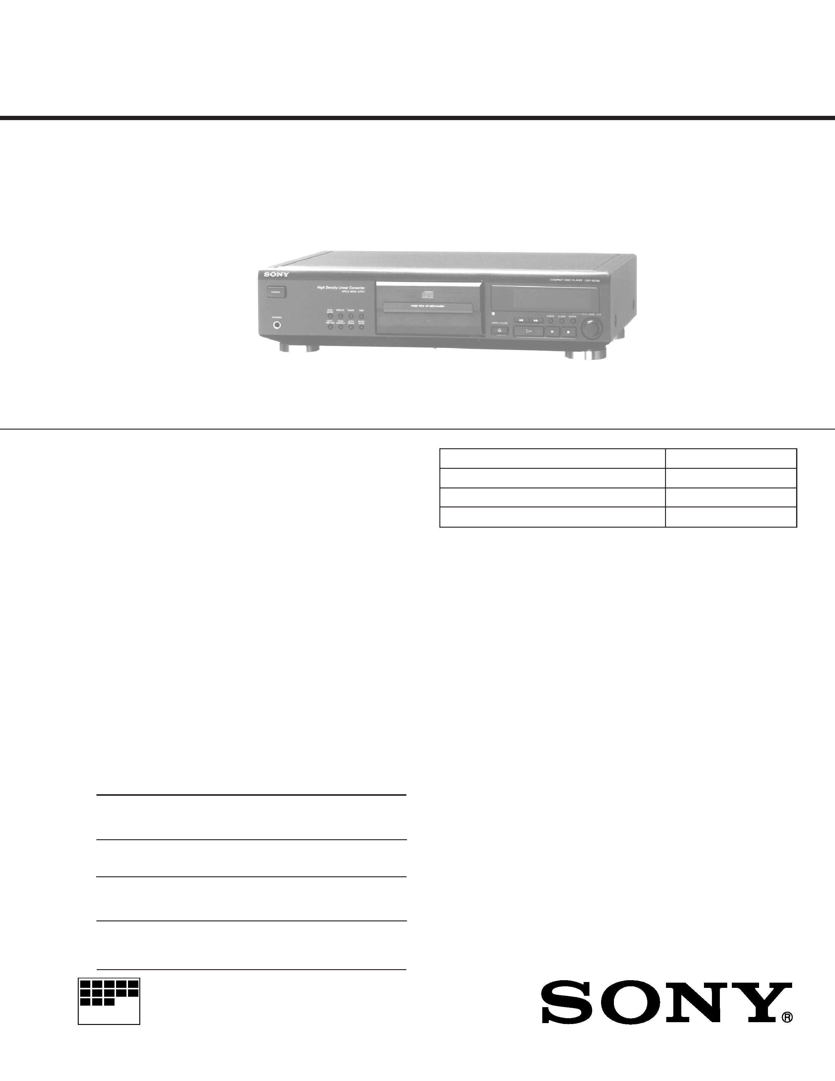
COMPACT DISC PLAYER
CDP-XE700
AEP Model
UK Model
Compact disc player
Laser
Semiconductor laser (
= 780 nm)
Emission duration: continuous
Laser output
Max 44.6 µW*
* This output is the value measured at
a distance of 200 mm from the
objective lens surface on the Optical Pick-
up block with 7 mm aperture.
Frequency response
2 Hz to 20 kHz ± 0.5 dB
Signal-to-noise ratio
More than 102 dB
Dynamic range
More the 98 dB
Harmonic distortion
Less than 0.0035%
Channel separation
More than 100 dB
General
Power requirements
220 V 230 V AC, 50/60 Hz
Power consumption
12W
Dimensions (approx.)
430
× 1107 × 295 mm
(w/h/d)
(17
× 4 1/4 × 11 5/8 in.) incl. projecting
parts
Mass (approx.)
3.6 kg (7 lbs 15 oz)
Supplied accessories
Audio cord (2 phono plugs2 phono plugs) (1)
Remote commander (RM-D820) (1)
Sony SUM-3 (NS) batteries (2)
Design and specifications are subject to change without notice.
PHOTO : AEP model
SERVICE MANUAL
Outputs
Jack
Maximum
Load
type
output
impedance
level
LINE OUT
Phono
2 V
Over 50 kilohms
jacks
(at 50 kilohms)
DIGITAL
Optical
18 dBm
Wave length : 660 nm
OUT
output
(OPTICAL)
connector
PHONES
Stereo
10 mW
32 ohms
phone
jack
-- 2 --
SAFETY-RELATED COMPONENT WARNING !!
COMPONENTS IDENTIFIED BY MARK
! OR DOTTED
LINE WITH MARK
! ON THE SCHEMATIC DIAGRAMS
AND IN THE PARTS LIST ARE CRITICAL TO SAFE
OPERATION. REPLACE THESE COMPONENTS WITH
SONY PARTS WHOSE PART NUMBERS APPEAR AS
SHOWN IN THIS MANUAL OR IN SUPPLEMENTS
PUBLISHED BY SONY.
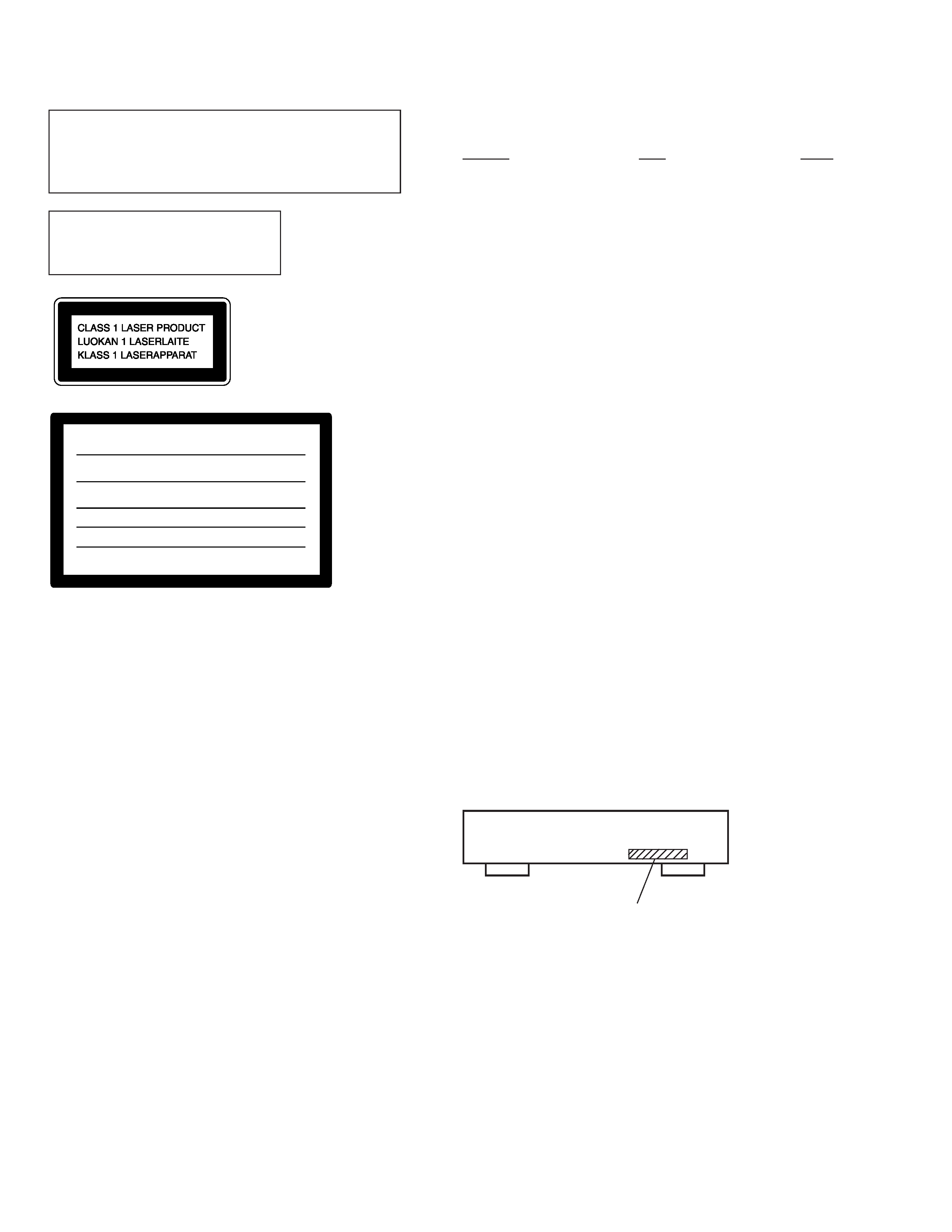
This appliance is classified as
a CLASS 1 LASER product.
The CLASS 1 LASER
PRODUCT MARKING is
located on the rear exterior.
CAUTION
Use of controls or adjustments or performance of procedures
other than those specified herein may result in hazardous ra-
diation exposure.
Notes on chip component replacement
· Never reuse a disconnected chip component.
· Notice that the minus side of a tantalum capacitor may be
damaged by heat.
Flexible Circuit Board Repairing
· Keep the temperature of soldering iron around 270°C
during repairing.
· Do not touch the soldering iron on the same conductor of the
circuit board (within 3 times).
· Be careful not to apply force on the conductor when soldering
or unsoldering.
This caution
label is located
inside the unit.
TABLE OF CONTENTS
Section
Title
Page
SECTION 1. SERVICING NOTE ................................... 3
SECTION 2. GENERAL ...................................................... 4
SECTION 3. DISASSEMBLY
3-1.
Front Panel Assembly ......................................................... 5
SECTION 4. TEST MODE .............................................. 6
SECTION 5. ELECTRICAL BLOCK CHECKING ...... 8
SECTION 6. DIAGRAMS
6-1.
Circuit Boards Location ................................................... 10
6-2.
IC Pin Function
· IC801 System Control,
Fluorescent Indicator Tube Drive (CXP82316-069Q) .. 11
6-3.
Printed Wiring Board -- BD Section -- .......................... 13
6-4.
Schematic Diagram -- BD Section -- ............................. 15
6-5.
Printed Wiring Board -- Main Section -- ....................... 20
6-6.
Schematic Diagram -- Main Section -- .......................... 23
SECTION 7. EXPLODED VIEWS
7-1.
Front Panel Section .......................................................... 27
7-2.
Chassis Section ................................................................. 28
7-3.
CD Mechanism Section (CDM36-14) .............................. 29
7-4.
Base Unit Section (BU-14) ............................................... 30
SECTION 8. ELECTRICAL PARTS LIST ................. 31
ADVARSEL : USYNLIG LASERSTRÅLING VED ÅBNING NÅR
SIKKERHEDSAFBRYDERE ER UDE AF FUNKTION. UNDGÅ UDSAETTELSE
FOR STRÅLING.
CAUTION : INVISIBLE LASER RADIATION WHEN OPEN AND
INTERLOCKS DEFEATED. AVOID EXPOSURE TO BEAM.
VARO! : AVATTAESSA JA SUOJALUKITUS OHITETTAESSA OLET ALT-
TIINA NÄKYMÄTTÖMÄLLE LASERSÄTEILYLLE. ÄLÄ KATSO SÄTEESEEN.
VARNING : OSYNLIG LASERSTRÅLING NÄR DENNA DEL ÄR ÖPP-
NAD OCH SPÄRREN ÄR URKOPPLAD. BETRAKTA EJ STRÅLEN.
VORSICHT : UNSICHTBARE LASERSTRAHLUNG, WENN
ABDECKUNG GEÖFFNET UND SICHEREITSVERRIEGELUNG
ÜBERBRÜCKT. NICHT DEM STRAHL AUSSETZEN.
ADVARSEL : USYNLIG LASERSTRÅLING NÅR DEKSEL ÅPNES OG
SIKKERHEDSLÅS BRYTES. UNNGÅ EKSPONERING FOR STRÅLEN.
The laser component in this product
is capable of emitting radiation
exceeding the limit for Class 1.
MODEL IDENTIFICATION
-- BACK PANEL --
4-978-904-1
: AEP, German model
4-979-904-8
: UK model
-- 3 --
SECTION 1
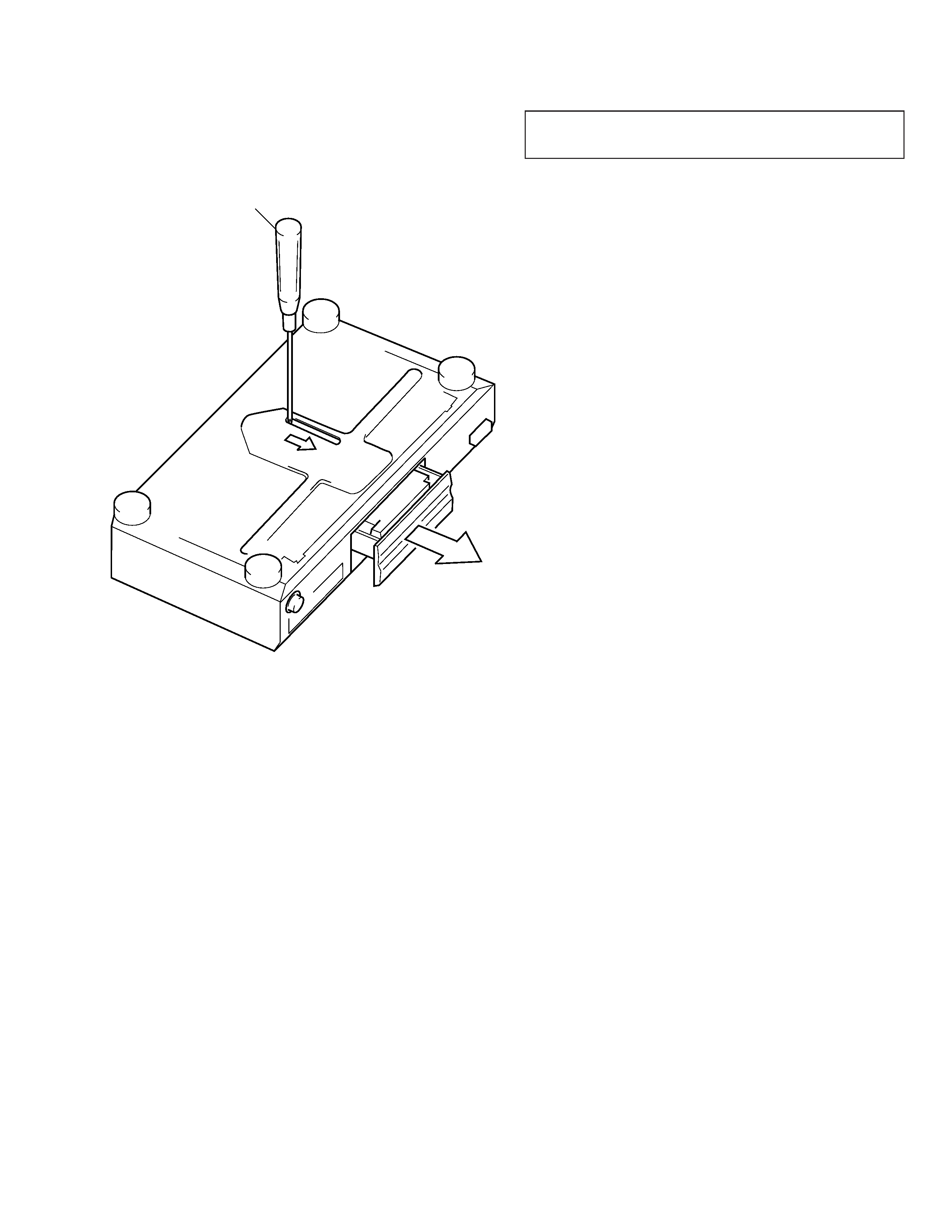
SERVICING NOTE
HOW TO OPEN THE DISC TRAY WHEN POWER SWITCH
TURNS OFF
Insert a screwdriver into the aperture of the unit bottom, and
move it in the direction of arrow.
NOTES ON HANDLING THE OPTICAL PICK-UP BLOCK
OR BASE UNIT
The laser diode in the optical pick-up block may suffer
electrostatic breakdown because of the potential difference
generated by the charged electrostatic load, etc. on clothing and
the human body.
During repair, pay attention to electrostatic breakdown and also
use the procedure in the printed matter which is included in the
repair parts.
The flexible board is easily damaged and should be handled with
care.
NOTES ON LASER DIODE EMISSION CHECK
The laser beam on this model is concentrated so as to be focused
on the disc reflective surface by the objective lens in the optical pick-
up block. Therefore, when checking the laser diode emission,
observe from more than 30 cm away from the objective lens.
LASER DIODE AND FOCUS SEARCH OPERATION
CHECK
Carry out the "S curve check" in "CD section adjustment" and
check that the S curve waveform is output three times.
-- 4 --
SECTION 2
GENERAL
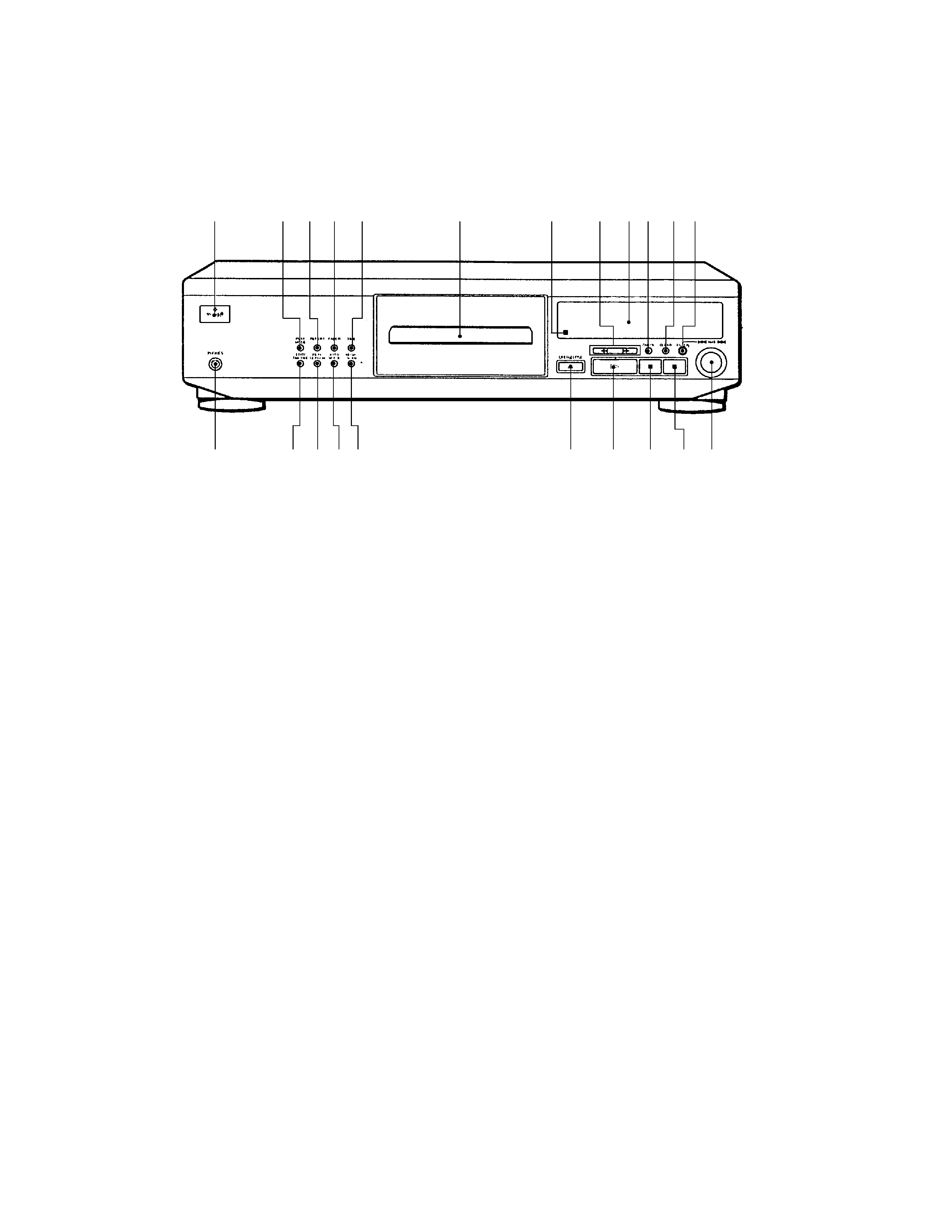
LOCATION OF PARTS AND CONTROLS
Front Panel
12 3 4 5
6
7
8 90 !¡!TM
!£
!¢
!
!§
!¶
!·
@º !ª
@¡
@TM
1 POWER switch
2 PLAY MODE button
3 REPEAT button
4 FADER button
5 TIME button
6 Disc tray
7 Remote sensor
8 0/) buttons
9 Display window
0 CHECK button
!¡ CLEAR button
!TM ENTER button
!£ AMS* ± knob
!¢ p (stop) button
! P (pause) button
!§ · (play) button
!¶ § OPEN/CLOSE button
!· MUSIC SCAN button
!ª AUTO SPACE button
@º PEAK SEARCH button
@¡ EDIT/TIME FADE button
@TM PHONES jack (EXCEPT UK)
* AMS is the abbreviation for Automatic Music Sensor.
-- 5 --
SECTION 3
DISASSEMBLY
Note : Follow the disassembly procedure in the numerical order given.
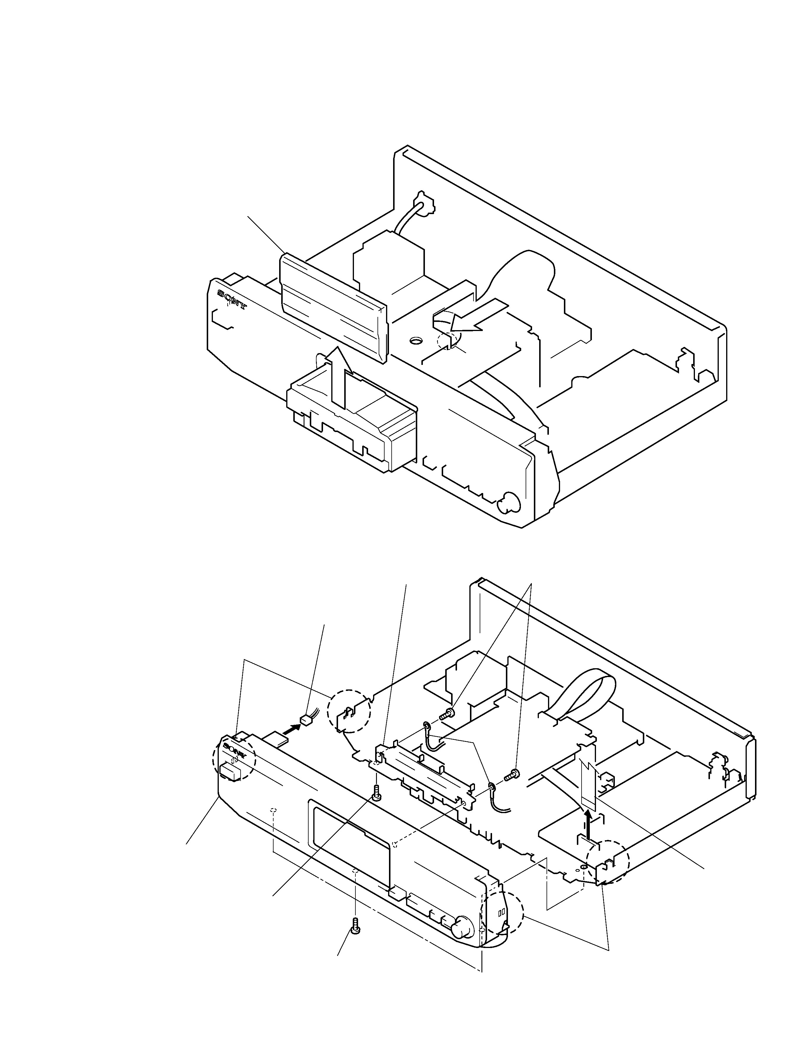
3-1. FRONT PANEL ASSEMBLY
1 Push the part A in the direction of arrow to
remove the loading panel upward.
A part
6 Two screws
(BVTP2.6x8)
8 Panel bracket
4 Connector
(CN751)
Claw
3 Screw (BVTP3x8)
(AEP, G only)
2 Three screws
(BVTP3x8)
5 Connector (CN302)
(Flat type 23 core)
Claw
7 Wire
9 Remove the front panel assembly
with care to claws.