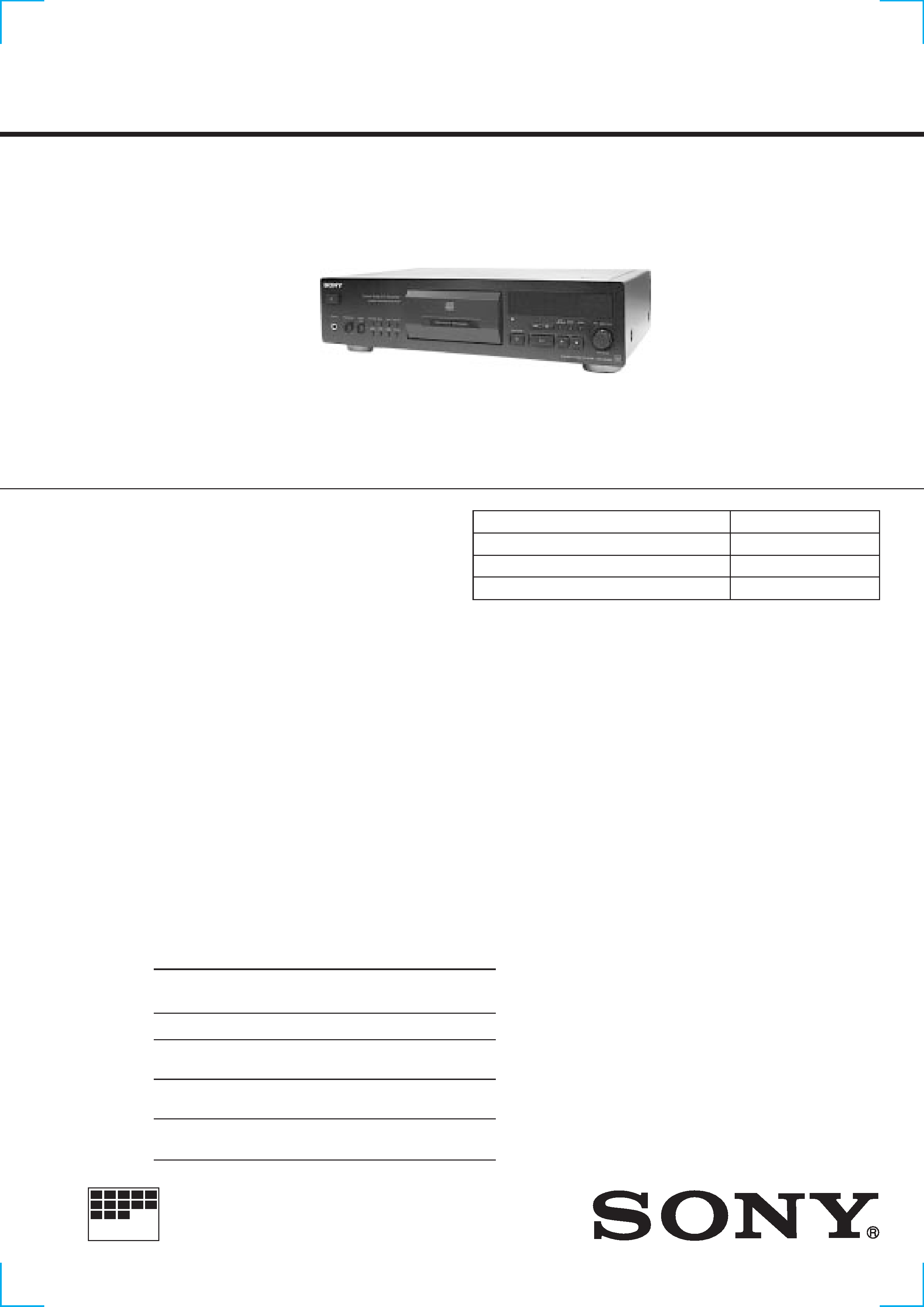
CDP-XB930/XB930E
AEP Model
CDP-XB930
UK Model
E Model
CDP-XB930E
SERVICE MANUAL
COMPACT DISC PLAYER
MICROFILM
Manufactured under license from Dolby Laboratories
Licensing Corporation.
"DOLBY" and the double-D symbol
aare trademarks
of Dolby Laboratories Licensing Corporation.
SPECIFICATIONS
Model Name Using Similar Mechanism
CDP-XB920/XB920E
CD Mechanism Type
CDM36C-14D
Base Unit Type
BU-14D
Optical Pick-up Type
KSS-213B/K-N
PHOTO : CDP-XB930 (BLACK Model)
Compact disc player
Laser
Semiconductor laser (
= 780 nm)
Emission duration: continuous
Laser output
Max 44.6 µW*
* This output is the value measured at
a distance of 200 mm from the
objective lens surface on the Optical
Pick-up block with 7 mm aperture.
Frequency response
2 Hz to 20 kHz ± 0.5 dB
Signal-to-noise ratio
More than 113 dB
Dynamic range
More than 99 dB
Harmonic distortion
Less than 0.0025%
Channel separation
More than 105 dB
General
Power requirements
220 V 230 V AC, 50/60 Hz
Power consumption
15W
Dimensions (approx.)
430
× 115 × 290 mm
(w/h/d)
(17
× 4 5/8 × 11 1/2 in.) incl.
projecting parts
Mass (approx.)
6.0 kg (13 lbs 04 oz)
Supplied accessories
Audio cord (2 phono plugs2 phono plugs) (1)
Remote commander (remote) (1)
R6 (size AA) batteries (2)
Stabilizer (1)
Design and specifications are subject to change without notice.
Outputs
Jack
Maximum
Load
type
output
impedance
level
LINE OUT
Phono
2 V
Over 50 k
jacks
(at 50 k
)
DIGITAL
Optical
OUT
output
18 dBm
Wave length:660nm
(OPTICAL)
connector
DIGITAL
Coaxial
0.5 Vp-p
OUT
output
(at 75
)
75
(COAXIAL)
connector
PHONES
Stereo
(only for CDP-XB930)
phone
10 mW
32
jack
2
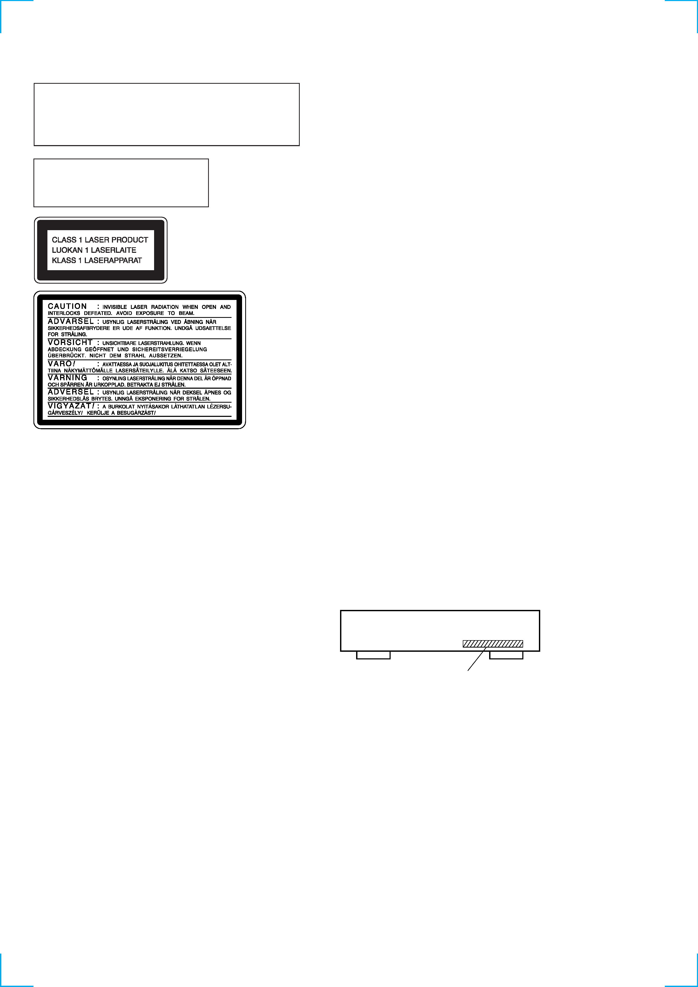
This appliance is classified as
a CLASS 1 LASER product.
The CLASS 1 LASER
PRODUCT MARKING is
located on the rear exterior.
TABLE OF CONTENTS
1. SERVICING NOTE ···························································· 5
2. GENERAL ············································································ 6
3. DISASSEMBLY
3-1.
Slide Rack ··········································································· 8
3-2.
Front Panel ········································································· 8
4. TEST MODE ········································································ 9
5. ELECTRICAL BLOCK CHECKING ····························· 11
6. DIAGRAMS
6-1.
Circuit Boards Location ··················································· 13
6-2.
Block Diagram ································································· 14
6-3.
Schematic Diagram
Main Section (1/2) ························ 15
6-4.
Schematic Diagram
Main Section (2/2) ························ 16
6-5.
Printed Wiring Board
Main Section ······························ 17
6-6.
Schematic Diagram Display Section ······························ 18
6-7.
Printed Wiring Board
Display Section ·························· 19
6-8.
Schematic Diagram
Power section ································ 20
6-9.
Printed Wiring Board
Power section ····························· 21
6-10. Schematic Diagram
Servo section ································· 22
6-11. Printed Wiring Board
Servo section ······························ 23
6-12. Schematic Diagram
Motor section ································ 24
6-13. Printed Wiring Board
Motor section ····························· 24
6-14. IC Block Diagrams ··························································· 25
6-15. IC Pin Function Description ············································· 27
7. EXPLODED VIEWS ·················································· 31
8. ELECTRICAL PARTS LIST ········································· 36
The laser component in this product
is capable of emitting radiation
exceeding the limit for Class 1.
SAFETY-RELATED COMPONENT WARNING !!
COMPONENTS IDENTIFIED BY MARK
! OR DOT-
TED LINE WITH MARK
! ON THE SCHEMATIC
DIAGRAMS AND IN THE PARTS LIST ARE CRITICAL
TO SAFE OPERATION. REPLACE THESE COMPO-
NENTS WITH SONY PARTS WHOSE PART NUM-
BERS APPEAR AS SHOWN IN THIS MANUAL OR IN
SUPPLEMENTS PUBLISHED BY SONY.
Notes on chip component replacement
· Never reuse a disconnected chip component.
· Notice that the minus side of a tantalum capacitor may be
damaged by heat.
Flexible Circuit Board Repairing
· Keep the temperature of soldering iron around 270°C during
repairing.
· Do not touch the soldering iron on the same conductor of the
circuit board (within 3 times).
· Be careful not to apply force on the conductor when soldering
or unsoldering.
This caution
label is located
inside the unit.
CAUTION
Use of controls or adjustments or performance of procedures
other than those specified herein may result in hazardous
radiation exposure.
MODEL IDENTIFICATION
-- BACK PANEL --
4-219-772-0: XB930 (AEP) model
4-219-772-1: XB930E (UK) model
4-219-772-2: XB930E (Singapore) model
3
CD-TEXT TEST DISC
This unit is able to display the test data (character information) written in the CD on its fluorescent indicator tube.
The CD-TEXT TEST DISC (TGCS-313:4-989-366-01) is used for checking the display.
To check, perform the following procedure.
Checking Method:
1.
Turn ON the power, set the disc on a tray, and chuck the disc.
2.
Press the · button and play back the disc.
3.
The following will be displayed on the fluorescent indicator tube.
Display : 1KHZ/0 DB
4.
Rotate AMS ± knob to switch the track. The text data of each track will be displayed.
For details of the displayed contents for each track, refer to "Table 1 : CD-TEXT TEST DISC Recorded Contents and Display".
Restrictions in CD-TEXT Display
In this unit, some special characters will not be displayed properly. These will be displayed as a space or a character resembling it.
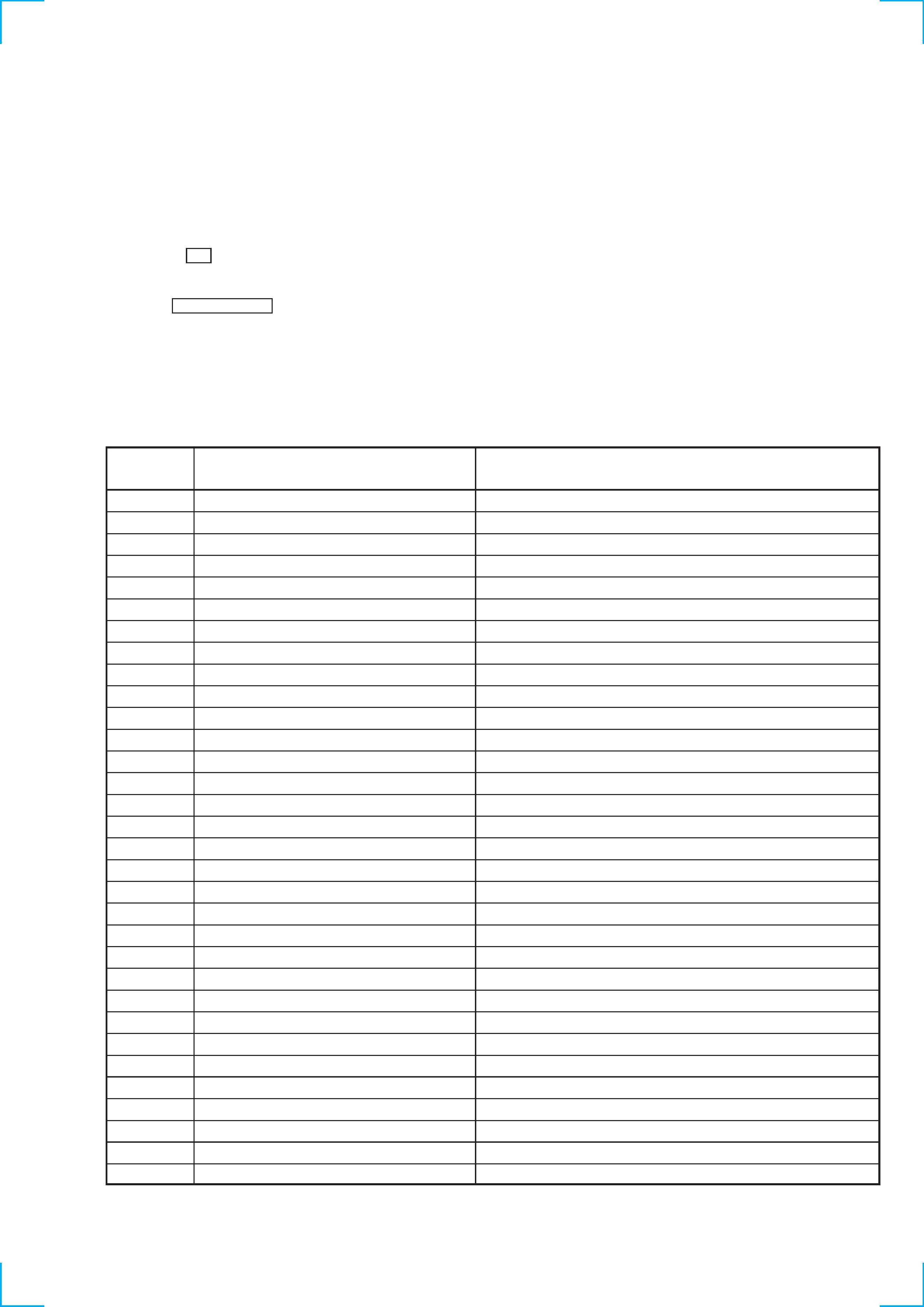
Table 1 :
CD-TEXT TEST DISC Recorded Data Contents and Display (TRACKS No. 1 to 32:Normal
Characters)
TRACK
No.
Recorded contents
Display
1
2
3
4
5
6
7
8
9
10
11
12
13
14
15
16
17
18
19
20
21
22
23
24
25
26
27
28
29
30
31
32
1kHz/0dB/L&R
20Hz/0dB/L&R
40Hz/0dB/L&R
100Hz/0dB/L&R
200Hz/0dB/L&R
500Hz/0dB/L&R
1kHz/0dB/L&R
5kHz/0dB/L&R
7kHz/0dB/L&R
10kHz/0dB/L&R
16kHz/0dB/L&R
18kHz/0dB/L&R
20kHz/0dB/L&R
1kHz/0dB/L&R
1kHz/-1dB/L&R
1kHz/-3dB/L&R
1kHz/-6dB/L&R
1kHz/-10dB/L&R
1kHz/-20dB/L&R
1kHz/-60dB/L&R
1kHz/-80dB/L&R
1kHz/-90dB/L&R
Infinity Zero w/o emphasis//L&R
Infinity Zero with emphasis//L&R
400Hz+7kHz(4:1)/0dB/L&R
400Hz+7kHz(4:1)/-10dB/L&R
19kHz+20kHz(1:1)/0dB/L&R
19kHz+20kHz(1:1)/-10dB/L&R
100Hz/0dB/L*
1kHz/0dB/L*
10kHz/0dB/L*
20kHz/0dB/L*
1 K H Z / 0 D B
/L&R are not displayed
2 0 H Z / 0 D B
/L&R are not displayed
4 0 H Z / 0 D B
/L&R are not displayed
1 0 0 H Z / 0 D
B/L&R are not displayed
2 0 0 H Z / 0 D
B/L&R are not displayed
5 0 0 H Z / 0 D
B/L&R are not displayed
1 K H Z / 0 D B
/L&R are not displayed
5 K H Z / 0 D B
/L&R are not displayed
7 K H Z / 0 D B
/L&R are not displayed
1 0 K H Z / 0 D
B/L&R are not displayed
1 6 K H Z / 0 D
B/L&R are not displayed
1 8 K H Z / 0 D
B/L&R are not displayed
2 0 K H Z / 0 D
B/L&R are not displayed
1 K H Z / 0 D B
/L&R are not displayed
1 K H Z / - 1 D
B/L&R are not displayed
1 K H Z / - 3 D
B/L&R are not displayed
1 K H Z / - 6 D
B/L&R are not displayed
1 K H Z / - 1 0
dB/L&R are not displayed
1 K H Z / - 2 0
dB/L&R are not displayed
1 K H Z / - 6 0
dB/L&R are not displayed
1 K H Z / - 8 0
dB/L&R are not displayed
1 K H Z / - 9 0
dB/L&R are not displayed
I N F I N I T Y
Zero w/o emphasis//L&R are not displayed
I N F I N I T Y
Zero with emphasis//L&R are not displayed
4 0 0 H Z+ 7 K
Hz(4:1)/0dB/L&R are not displayed
4 0 0 HZ + 7 K
Hz(4:1)/-10dB/L&R are not displayed
1 9 K H Z+ 2 0
Hz(1:1)/0dB/L&R are not displayed
1 9 K H Z+ 2 0
Hz(1:1)/-10dB/L&R are not displayed
1 0 0 H Z / 0 D
B/L are not displayed
1 K H Z / 0 D B
/L are not displayed
1 0 K H Z / 0 D
B/L are not displayed
2 0 K H Z / 0 D
B/L are not displayed
* Other channel is infinity zero.
4
1 0 0 H Z / 0 D B/R are not displayed
1 K H Z / 0 D B /R are not displayed
1 0 K H Z / 0 D B/R are not displayed
2 0 K H Z / 0 D B/R are not displayed
1 0 0 H Z
S Q uer Wave //L&R are not displayed
1 K H Z
S Q U er Wave //L&R are not displayed
1 K H Z W
/ E mphasis/-0.37dB/L&R are not displayed
5 K H Z W
/ E mphasis/-4.53dB/L&R are not displayed
1 6 K H Z W
/ emphasis/-9.04dB/L&R are not
displayed
' ! " # $ % & (21h to27h)1kHz 0dB
L&R are not displayed
( ) * +
/ , . (28h to 2Fh) are not displayed
012 34567 (30h to 37h) are not displayed
8 9
=
? : ; < > (38h to 3Fh) are not displayed
A B C D E F G @ (40h to 47h) are not displayed
H I J K L M N O (48h to 4Fh) are not displayed
P Q R S T U V W (50h to 57h) are not displayed
X Y Z [\]^ _ (58h to 5Fh) are not displayed
A B C D E F G (60h to 67h) are not displayed
H I J K L M N O (68h to 6Fh) are not displayed
P Q R S T U V W (70h to 77h) are not displayed
X Y Z
{ I }
(78h to 7Fh) are not displayed
All no displayed
¬ C ª P R (A8h to AFh)are not
displayed
·
±
2 3 m ¶· (B0h to B7h) are not displayed
¿ 1 º
(B8h to BFh) are not
displayed
À Á Â Ã Ä Å
Æ Ç (C0h to C7h) are not displayed
È É Ê Ë ÌÍÎÏ (C8h to CFh) are not displayed
Ñ Ò ÓÔÕÖ
(D0h to D7h) are not displayed
Ù Ú Û Ü Y
(D8h to DFh) are not displayed
À Á Â Ã Ä Å
æ ç (E0h to E7h) are not displayed
È É Ê Ë ÌÍÎÏ (E8h to EFh) are not displayed
Ñ Ò ÓÔÕÖ
(F0h to F7h) are not displa yed
Ù Ú Û Ü Y
ø
ÿ (F8h to FFh) are not displayed
NO. 66
NO. 67
to
NO. 99
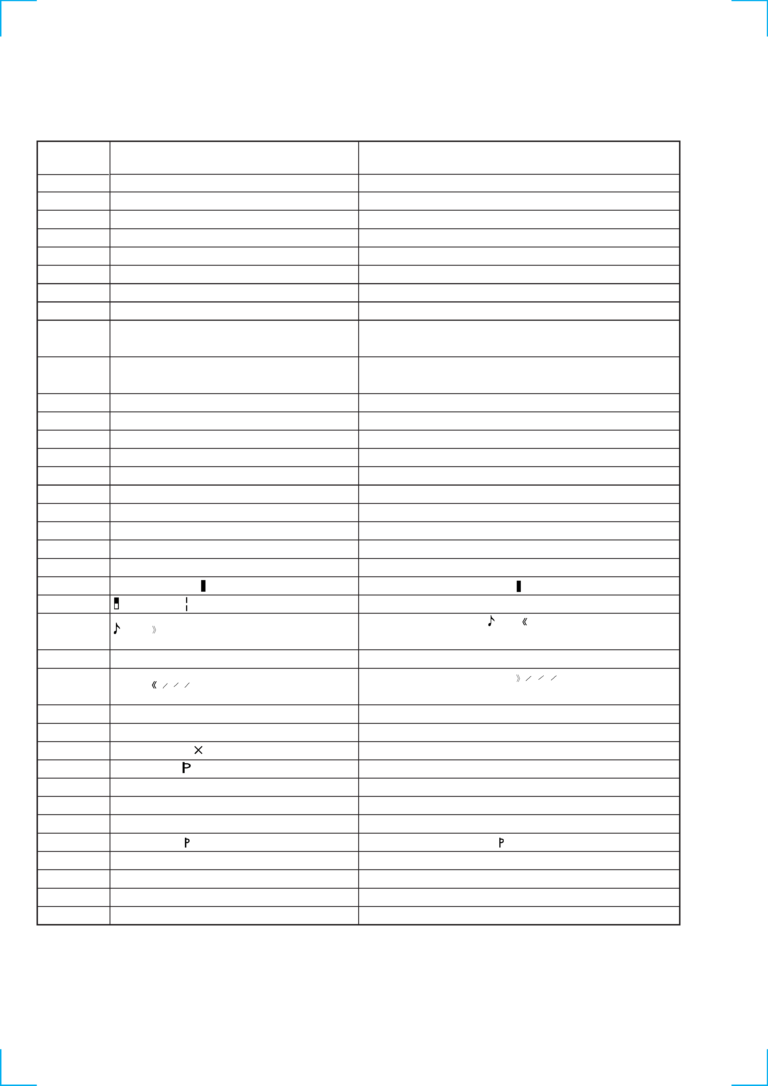
TRACK
Recorded contents
Display
Table 2: CD-TEXT TEST DISC Recorded Contents and Display (TRACKS NO. 33 to 99)
(In this unit, some special characters cannot be displayed. This is no a fault.)
~
~
3
4
1
2
1
4
3
4
1
2
1
4
* Other channel is infinity zero.
33
34
35
36
37
38
39
40
41
42
43
44
45
46
47
48
49
50
51
52
53
54
55
56
57
58
59
60
61
62
63
64
65
66
67
to
99
100Hz/0dB/R*
1kHz/0dB/R*
10kHz/0dB/R*
20kHz/0dB/R*
100Hz Squer Wave //L&R
1Hz Squer Wave //L&R
1kHz w/emphasis/-0.37dB/L&R
5kHz w/emphasis/-4.53dB/L&R
16kHz w/emphasis/-9.04dB/L&R
!
" # $ % & '
(21h to 27h)1kHz 0dB L&R
(
) * + , . / (28h to 2Fh)
0 1 2 3 4 5 6 7 (30h to 37h)
8 9 : ; < = > ? (38h to 3Fh)
@ A B C D E F G (40h to 47h)
H I J K L M N O (48h to 4Fh)
P Q R S T U V W (50h to 57h)
X Y Z [ ¥ ] ^ _ (58h to 5Fh)
a b c d e f g (60h to 67h)
h i j k l m n o (68h to 6Fh)
p q r s t u v w (70h to 77h)
x y z { I }
(78h to 7Fh)
i ¢ £ ¤ ¥
§ (A0h to A7h) 8859-1
C ª
¬ PR (A8h to AFh)
·
± 23
µ ¶ · (B0h to B7h)
1 º
¿ (B8h to BFh)
À Á Â Ã Ä Å ÆÇ (C0h to C7h)
È É Ê Ë ÌÍÎÏ (C8h to CFh)
D Ñ ÒÓÔÕÖ
(D0h to D7h)
ØÙ Ú Û Ü Y
ß (D8h to DFh)
à á â ã ä å æ ç (E0h to E7h)
è é ê ë ìíîï (E8h to EFh)
ñòó ôõ ö ÷ (F0h to F7h)
ø ùúû ü y
ÿ (F8h to FFh)
No.66
No.67
to
No.99
5
SECTION 1
SERVICING NOTE
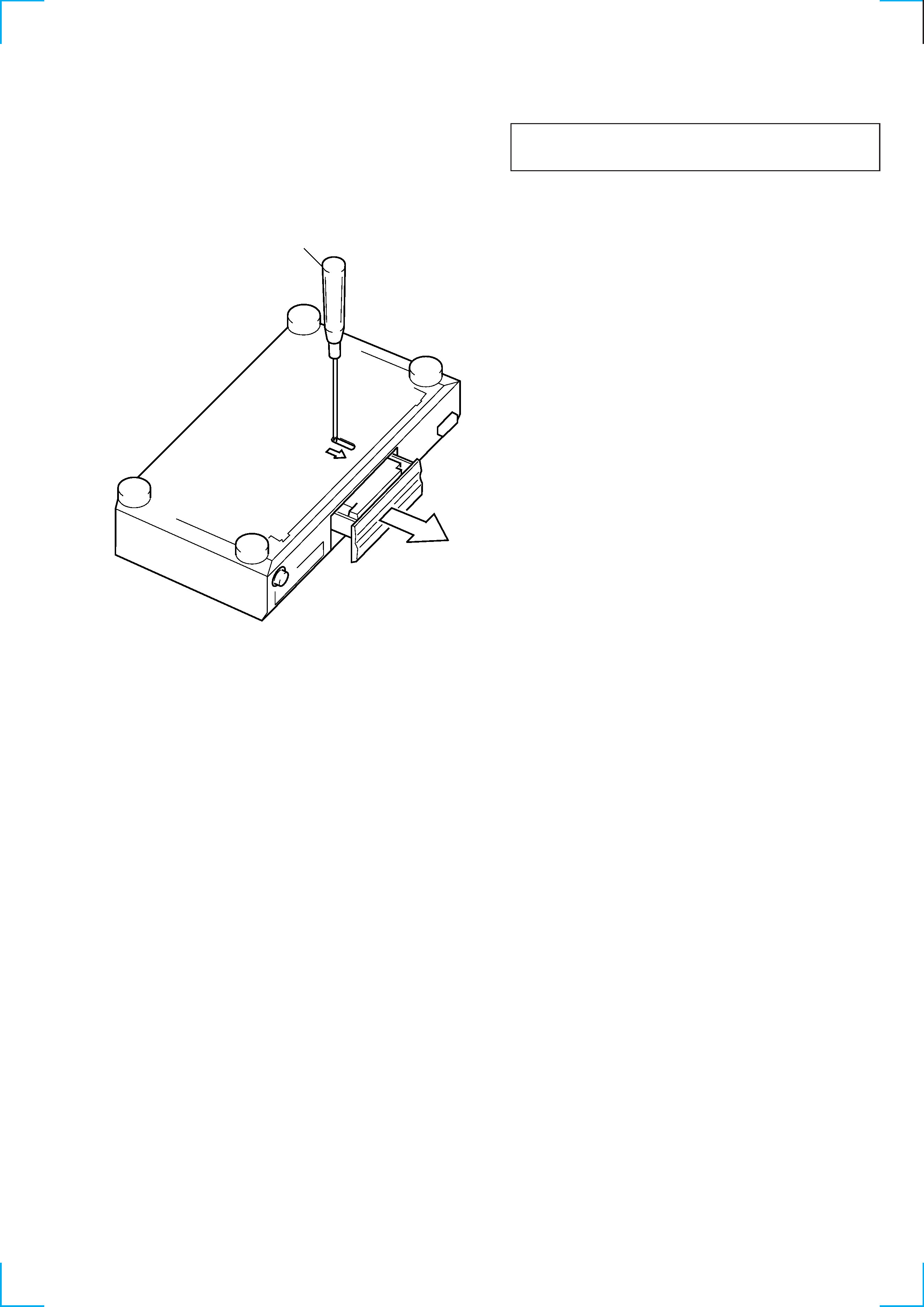
HOW TO OPEN THE DISC TRAY WHEN POWER SWITCH
TURNS OFF
Insert a screwdriver into the aperture of the unit bottom, and
move it in the direction of arrow.
NOTES ON HANDLING THE OPTICAL PICK-UP BLOCK
OR BASE UNIT
The laser diode in the optical pick-up block may suffer electrostatic
breakdown because of the potential difference generated by the
charged electrostatic load, etc. on clothing and the human body.
During repair, pay attention to electrostatic breakdown and also use
the procedure in the printed matter which is included in the repair
parts.
The flexible board is easily damaged and should be handled with
care.
NOTES ON LASER DIODE EMISSION CHECK
The laser beam on this model is concentrated so as to be focused on
the disc reflective surface by the objective lens in the optical pick-
up block. Therefore, when checking the laser diode emission,
observe from more than 30 cm away from the objective lens.
LASER DIODE AND FOCUS SEARCH OPERATION
CHECK
Carry out the "S curve check" in "CD section adjustment" and check
that the S curve waveform is output two times.