1
CDP-XB740/XB740E
AEP Model
CDP-XB740
UK Model
CDP-XB740E
SPECIFICATIONS
SERVICE MANUAL
COMPACT DISC PLAYER
Model Name Using Similar Mechanism
CDP-XB720/XB720E
CD Mechanism Type
CDM14FLS-5BD25
Base Unit Type
BU-5BD25
Optical Pick-up Type
KSS-213BA/F-NP
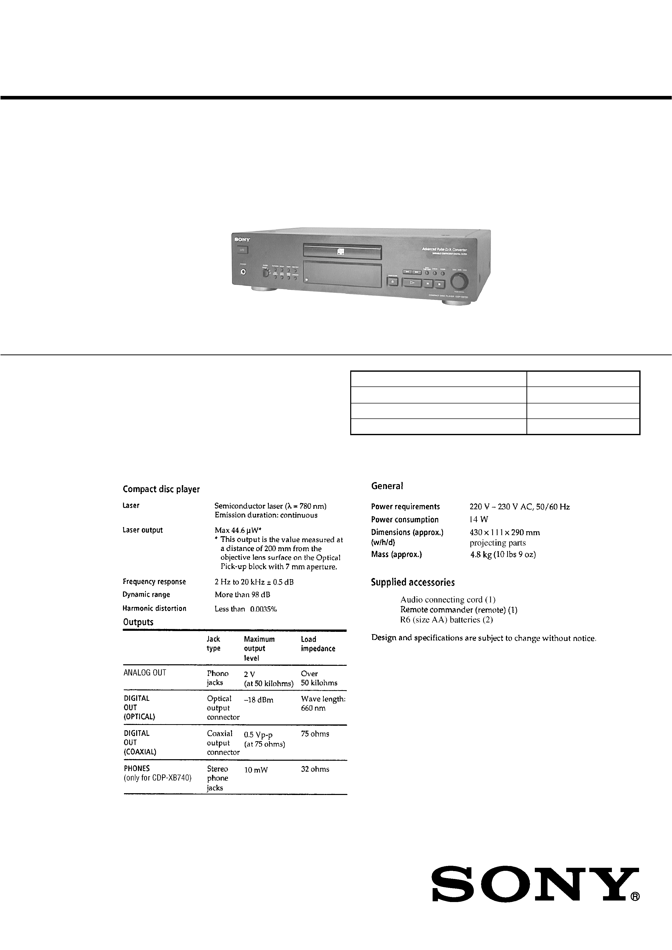
Photo: CDP-XB740
Ver 1.1 2001.02
Sony Corporation
Audio Entertainment Group
General Engineering Dept.
9-929-241-12
2001B0900-1
© 2001.2
2
SAFETY-RELATED COMPONENT WARNING !!
COMPONENTS IDENTIFIED BY MARK 0 OR DOTTED LINE
WITH MARK 0 ON THE SCHEMATIC DIAGRAMS AND IN
THE PARTS LIST ARE CRITICAL TO SAFE OPERATION.
REPLACE THESE COMPONENTS WITH SONY PARTS
WHOSE PART NUMBERS APPEAR AS SHOWN IN THIS
MANUAL OR IN SUPPLEMENTS PUBLISHED BY SONY.
CAUTION
Use of controls or adjustments or performance of procedures
other than those specified herein may result in hazardous ra-
diation exposure.
Notes on chip component replacement
· Never reuse a disconnected chip component.
· Notice that the minus side of a tantalum capacitor may be
damaged by heat.
Flexible Circuit Board Repairing
· Keep the temperature of soldering iron around 270°C
during repairing.
· Do not touch the soldering iron on the same conductor of the
circuit board (within 3 times).
· Be careful not to apply force on the conductor when soldering
or unsoldering.
Laser component in this product is capable of emitting radiation
exceeding the limit for Class 1.
This appliance is classified as
a CLASS 1 LASER product.
The CLASS 1 LASER PROD-
UCT MARKING is located on
the rear exterior.
PARTS No.
MODEL
MODEL IDENTIFICATION
-- BACK PANEL --
TABLE OF CONTENTS
1. SERVICING NOTE .......................................................... 3
2. GENERAL .......................................................................... 6
3. DISASSEMBLY
3-1. Front Panel ........................................................................... 7
3-2. Base Unit (BU-5BD25) ......................................................... 7
4. TEST MODE ....................................................................... 8
5. ELECTRICAL BLOCK CHECKING ........................ 10
6. DIAGRAMS
6-1. Circuit Boards Location ...................................................... 12
6-2. Printed Wiring Board BD Section ................................. 14
6-3. Schematic Diagram BD Section ................................... 15
6-4. Printed Wiring Board Main Section .............................. 16
6-5. Schematic Diagram Main Section ................................ 17
6-6. Printed Wiring Board Display Section .......................... 18
6-7. Schematic Diagram Display Section ............................ 19
6-8. Schematic Diagram Power/HP Section ........................ 20
6-9. Printed Wiring Board Power/HP Section ...................... 20
6-10. Schematic Diagram Loading Motor Section ............... 21
6-11. Printed Wiring Board Loading Motor Section ............ 21
6-12. IC Pin Functions ................................................................ 22
6-13. IC Block Diagrams ............................................................ 26
7. EXPLODED VIEWS
7-1. Case Section ........................................................................ 29
7-2. Front Panel Section ............................................................. 30
7-3. Mechanism Deck Section (CDM14FLS-5BD25) ............... 31
7-4. Base Unit Section (BU-5BD25) .......................................... 32
8. ELECTRICAL PARTS LIST ........................................ 33
4-997-214-6s
4-997-214-7s
XB740
XB740E
Parts No.
3
SECTION 1
SERVICING NOTE
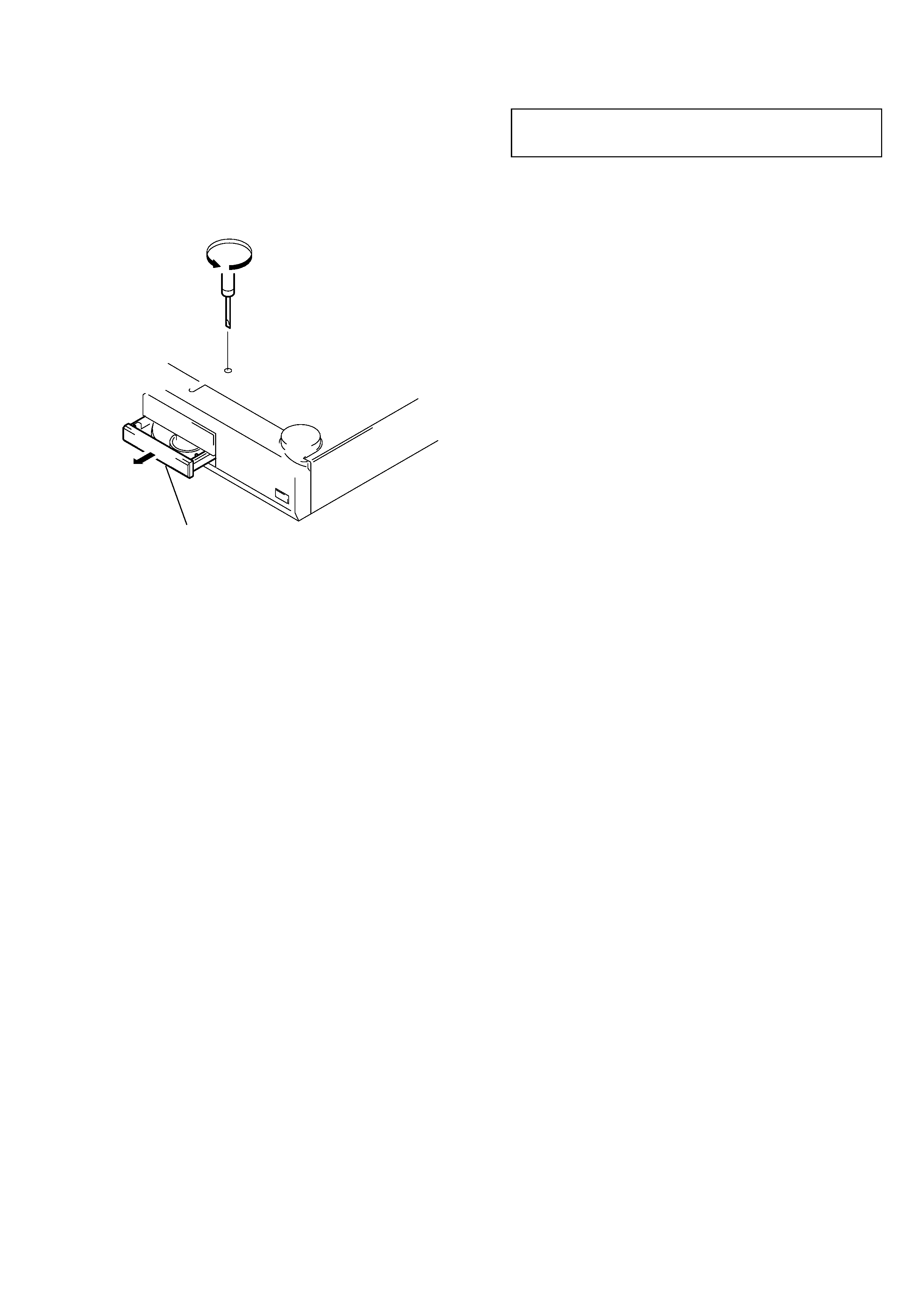
HOW TO OPEN THE DISC TRAY WHEN POWER SWITCH
TURNS OFF
Insert a tapering driver into the aperture of the unit bottom, and turn
in the direction of arrow.
* To close the disc table, turn the driver in the reverse direction.
Pull out disc table.
NOTES ON HANDLING THE OPTICAL PICK-UP BLOCK
OR BASE UNIT
The laser diode in the optical pick-up block may suffer
electrostatic breakdown because of the potential difference
generated by the charged electrostatic load, etc. on clothing and
the human body.
During repair, pay attention to electrostatic breakdown and also
use the procedure in the printed matter which is included in the
repair parts.
The flexible board is easily damaged and should be handled with
care.
NOTES ON LASER DIODE EMISSION CHECK
The laser beam on this model is concentrated so as to be focused
on the disc reflective surface by the objective lens in the optical
pick-up block. Therefore, when checking the laser diode emission,
observe from more than 30 cm away from the objective lens.
LASER DIODE AND FOCUS SEARCH OPERATION
CHECK
Carry out the "S curve check" in "CD section adjustment" and
check that the S curve waveform is output continuously.
4
Restrictions in CD-TEXT Display
In this unit, some special characters will not be displayed properly. These will be displayed as a space or a character resembling it. For details,
refer to "Table 2 : CD-TEXT DISC Recorded Contents and Display".
Table 1 : CD-TEXT TEST DISC TEXT Data Contents (TRACKS No. 1 to 41:Normal Characters)
1
2
3
4
5
6
7
8
9
10
11
12
13
14
15
16
17
18
19
20
21
TRACK
No.
Displayed Contents
22
23
24
25
26
27
28
29
30
31
32
33
34
35
36
37
38
39
40
41
TRACK
No.
Displayed Contents
1kHz/0dB/L&R
20Hz/0dB/L&R
40Hz/0dB/L&R
100Hz/0dB/L&R
200Hz/0dB/L&R
500Hz/0dB/L&R
1kHz/0dB/L&R
5kHz/0dB/L&R
7kHz/0dB/L&R
10kHz/0dB/L&R
16kHz/0dB/L&R
18kHz/0dB/L&R
20kHz/0dB/L&R
1kHz/0dB/L&R
1kHz/-1dB/L&R
1kHz/-3dB/L&R
1kHz/-6dB/L&R
1kHz/-10dB/L&R
1kHz/-20dB/L&R
1kHz/-60dB/L&R
1kHz/-80dB/L&R
1kHz/-90dB/L&R
Infinity Zero w/o emphasis//L&R
Infinity Zero with emphasis//L&R
400Hz+7kHz(4:1)/0dB/L&R
400Hz+7kHz(4:1)/-10dB/L&R
19kHz+20kHz(1:1)/0dB/L&R
19kHz+20kHz(1:1)/-10dB/L&R
100Hz/0dB/L*
1kHz/0dB/L*
10kHz/0dB/L*
20kHz/0dB/L*
100Hz/0dB/R*
1kHz/0dB/R*
10kHz/0dB/R*
20kHz/0dB/R*
100Hz Squer Wave//L&R
1kHz Squer Wave//L&R
1kHz w/emphasis/-0.37dB/L&R
5kHz w/emphasis/-4.53dB/L&R
16kHz w/emphasis/-9.04dB/L&R
NOTE : The contents of Track No. 1 to 41 are the same as those of the current TEST DISC-their titles are displayed.
However, only 8 digits are displayed, and the 9th digit onwards are displayed as " ".
CD-TEXT TEST DISC
This unit is able to display the TEXT data (character information)
written in the CD on its fluorescent indicator tube.
The CD-TEXT TEST DISC (TGCS-313: J-2501-126-A) is used
for checking the display.
To check, perform the following procedure.
Procedure:
1. Turn ON the power and set the test disc.
2. Press the B button and play back the disc.
3. The following will be displayed on the fluorescent indicator tube.
Display : CD TEXT
4. Rotate the l AMS L knob to switch the track. The text
data of each track will be displayed.
5
TRACK
No.
Recorded contents
Display
···· ! " # $ % & are not displayed
( )
+
/ ···· , . are not displayed
012 34567 ····
8 9
=
? ···· : ; < > are not displayed
A B C D E F G ···· @ is not displayed
H I J K L M N O ····
P Q R S T U V W ····
X Y Z [ / ] ^ _ ····
A B C D E F G ····
H I J K L M N O ····
P Q R S T U V W ····
X Y Z
···· { I }
are not displayed
····
i ¢ £ ¤ ¥ § are not displayed
¬
···· 9 C ª
P R
are not displayed
±
···· 2 3
µ ¶ · are not displayed
¿ ···· 1 º
are not displayed
À Á ÂÃÄÅ
···· Æ Ç are not displayed
È É Ê Ë Ì Í Î Ï ····
Ñ ÒÓÔÕÖ
···· D
are not displayed
ÙÚÛÜ Y
···· Ø
ß are not displayed
ÀÁ ÂÃÄÅ
···· æ ç are not displayed
È É Ê Ë Ì Í Î Ï ····
Ñ ÒÓÔÕÖ
····
÷ are not displayed
ÙÚÛÜ Y
···· ø ÿ are not displayed
T All the same
T All the same
to
T All the same
*
42
43
44
45
46
47
48
49
50
51
52
53
54
55
56
57
58
59
60
61
62
63
64
65
66
67
to
99
~
1
4
1
2
3
4
1
4
1
2
3
4
Table 2: CD-TEXT TEST DISC Recorded Contents and Display
(In this unit, some special characters cannot be displayed. This is no a fault.)
´
*
~
´
´
! " # $ % & ´
(21h to 27h)1kHz 0dB L&R
( )
+ , . /
(28h to 2Fh)
0 1234567
(30h to 37h)
8 9 : ; < = > ?
(38h to 3Fh)
@A B C D E F G
(40h to 47h)
H I J K L M N O
(48h to 4Fh)
P Q R S T U V W
(50h to 57h)
X Y Z [ ¥ ] ^ _
(58h to 5Fh)
a b c d e f g
(60h to 57h)
h i j k l m n o
(68h to 6Fh)
p q r s t u v w
(70h to 77h)
xy z { I }
(78h to 7Fh)
i ¢£¤¥
§
(A0h to A7h) 8859-1
9 C ª
¬
PR
(A8h to AFh)
·
± 23 µ ¶ · (B0h to B7h)
1 º
¿
(B8h to BFh)
ÀÁÂÃÄÅ Æ Ç
(C0h to C7h)
ÈÉÊË ÌÍÎÏ
(C8h to CFh)
D Ñ ÒÓÔ Õ Ö
(D0h to C7h)
Ø ÙÚÛÜ Y
ß
(D8h to DFh)
à áâãäå æ ç
(E0h to E7h)
è é ê ë ìíîï
(E8h to FFh)
ñòóôõö ÷ (F0h to F7h)
ø ùúûü y
ÿ
(F8h to FFh)
No.66
No.67
to
No.99
.
...