MICROFILM
AEP Model
UK Model
E Model
Chinese Model
SERVICE MANUAL
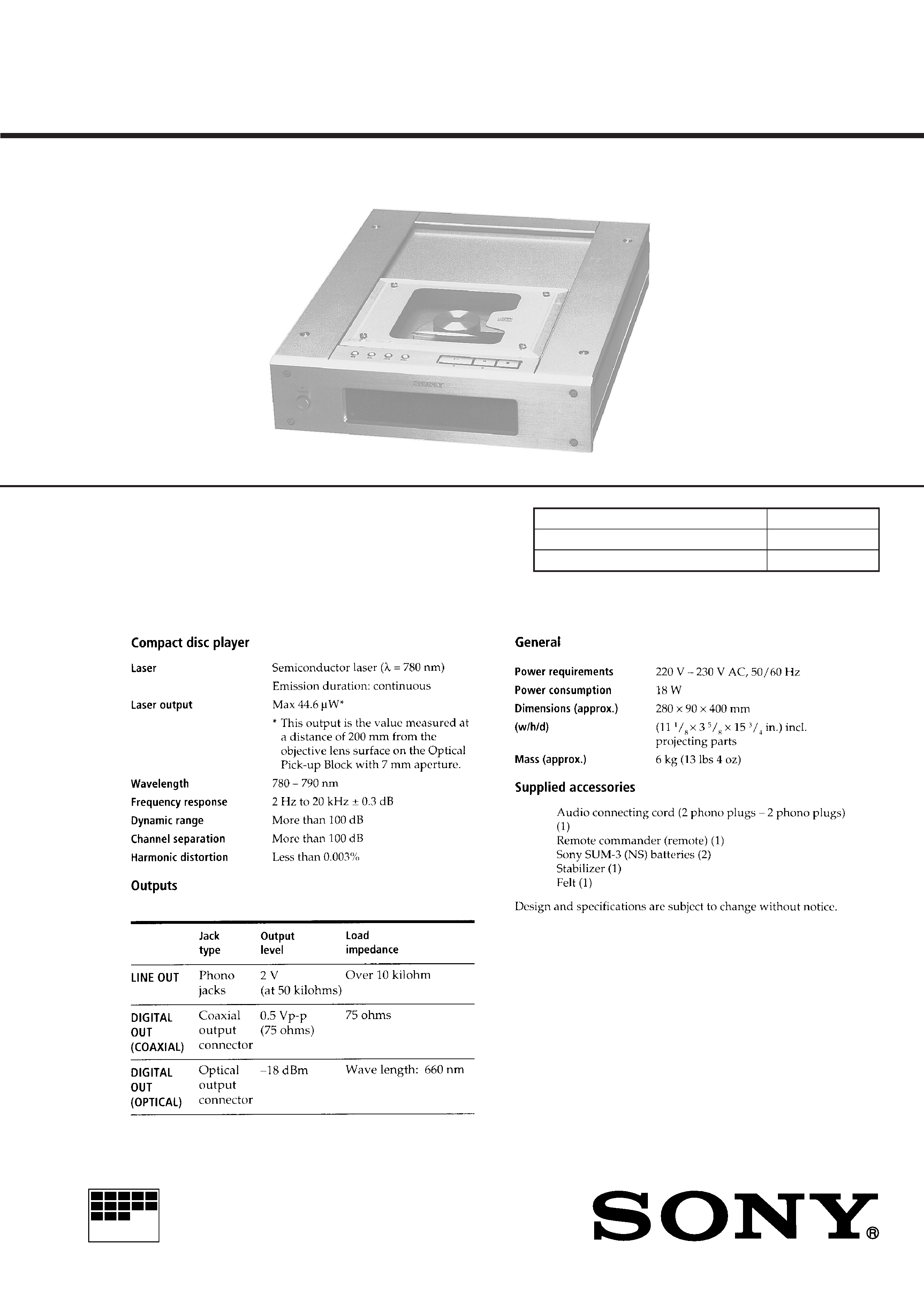
CDP-X3000/X3000ES
COMPACT DISC PLAYER
Model Name Using Similar Mechanism
NEW
Base Unit Type
BU-14B
Optical Pick-up Type
KSS-213B/S-N
SPECIFICATIONS
Photo: CDP-X3000
2
TABLE OF CONTENTS
1.
SERVICING NOTES
1-1.
Writing Focus/Tracking Auto Gain Data ......................... 3
1-2.
AF Mode .......................................................................... 3
1-3.
ADJ Mode ....................................................................... 4
1-4.
CLV-S Mode .................................................................... 4
2.
GENERAL ................................................................... 5
3.
DISASSEMBLY .......................................................... 10
4.
ELECTRICAL ADJUSTMENTS ......................... 14
5.
DIAGRAMS
5-1.
IC Pin Function Description ............................................ 16
5-2.
Printed Wiring Boards
Servo Section ............................................................. 22
5-3.
Schematic Diagram
Servo Section ............................................................. 25
5-4.
Schematic Diagram
Audio Section ............................................................ 29
5-5.
Printed Wiring Boards
Audio Section ............................................................ 34
5-6.
Printed Wiring Boards
Power Section ............................................................ 39
5-7.
Schematic Diagram
Power Section ............................................................ 41
5-8.
Schematic Diagram
Control Section .......................................................... 43
5-9.
Printed Wiring Boards
Control Section .......................................................... 45
6.
EXPLODED VIEWS ................................................ 52
7.
ELECTRICAL PARTS LIST ................................ 56
NOTES ON HANDLING THE OPTICAL PICK-UP
BLOCK OR BASE UNIT
The laser diode in the optical pick-up block may suffer electro-
static break-down because of the potential difference generated
by the charged electrostatic load, etc. on clothing and the human
body.
During repair, pay attention to electrostatic break-down and also
use the procedure in the printed matter which is included in the
repair parts.
The flexible board is easily damaged and should be handled with
care.
NOTES ON LASER DIODE EMISSION CHECK
The laser beam on this model is concentrated so as to be focused
on the disc reflective surface by the objective lens in the optical
pick-up block. Therefore, when checking the laser diode emis-
sion, observe from more than 30 cm away from the objective lens.
LASER DIODE AND FOCUS SEARCH OPERATION
CHECK
Carry out the "S curve check" in "CD section adjustment" and
check that the S curve waveforms is output three times.
Notes on chip component replacement
· Never reuse a disconnected chip component.
· Notice that the minus side of a tantalum capacitor may be dam-
aged by heat.
Flexible Circuit Board Repairing
· Keep the temperature of the soldering iron around 270 °C dur-
ing repairing.
· Do not touch the soldering iron on the same conductor of the
circuit board (within 3 times).
· Be careful not to apply force on the conductor when soldering
or unsoldering.
This appliance is classified as a CLASS 1 LASER product.
The CLASS 1 LASER PRODUCT MARKING is located on
the rear exterior.
Laser component in this product is capable of emitting radiation
exceeding the limit for Class 1.
The following caution label is located inside the unit.
SAFETY-RELATED COMPONENT WARNING!!
COMPONENTS IDENTIFIED BY MARK
! OR DOTTED LINE
WITH MARK
! ON THE SCHEMATIC DIAGRAMS AND IN
THE PARTS LIST ARE CRITICAL TO SAFE OPERATION.
REPLACE THESE COMPONENTS WITH SONY PARTS WHOSE
PART NUMBERS APPEAR AS SHOWN IN THIS MANUAL
OR IN SUPPLEMENTS PUBLISHED BY SONY.
CAUTION
Use of controls or adjustments or performance of
procedures other than those specified herein may
result in hazardous radiation exposure.
3
SECTION 1
SERVICING NOTES
1-1. WRITING FOCUS/TRACKING AUTO GAIN
DATA
In general for the CD players that use a digital servo IC, the focus/
tracking gain is automatically adjusted each time a disc is changed.
In this set, the gain in test disc (YEDS-18) has been written to a
nonvolatile memory (IC803: X24C01S) on the Display Board, and
therefore the gain is not readjusted even if a disc is changed.
Accordingly, always write auto gain data when replacing the Servo
Board, IC803 on Display Board, or optical pick-up.
1) Connect CN805 1 pin (IN/OUT SW) and 6 pin (GND) on
Display Board.
Under this condition, the set will operate even when the disc lid
is open (or Key Board is not connected).
2) Connect TP (ADJ: CN105 3 pin) on Servo Board to GND, and
TP (VC: CN108 2 Pin) to TP3 (TEI: IC105 @¶ pin) with lead
wires respectively.
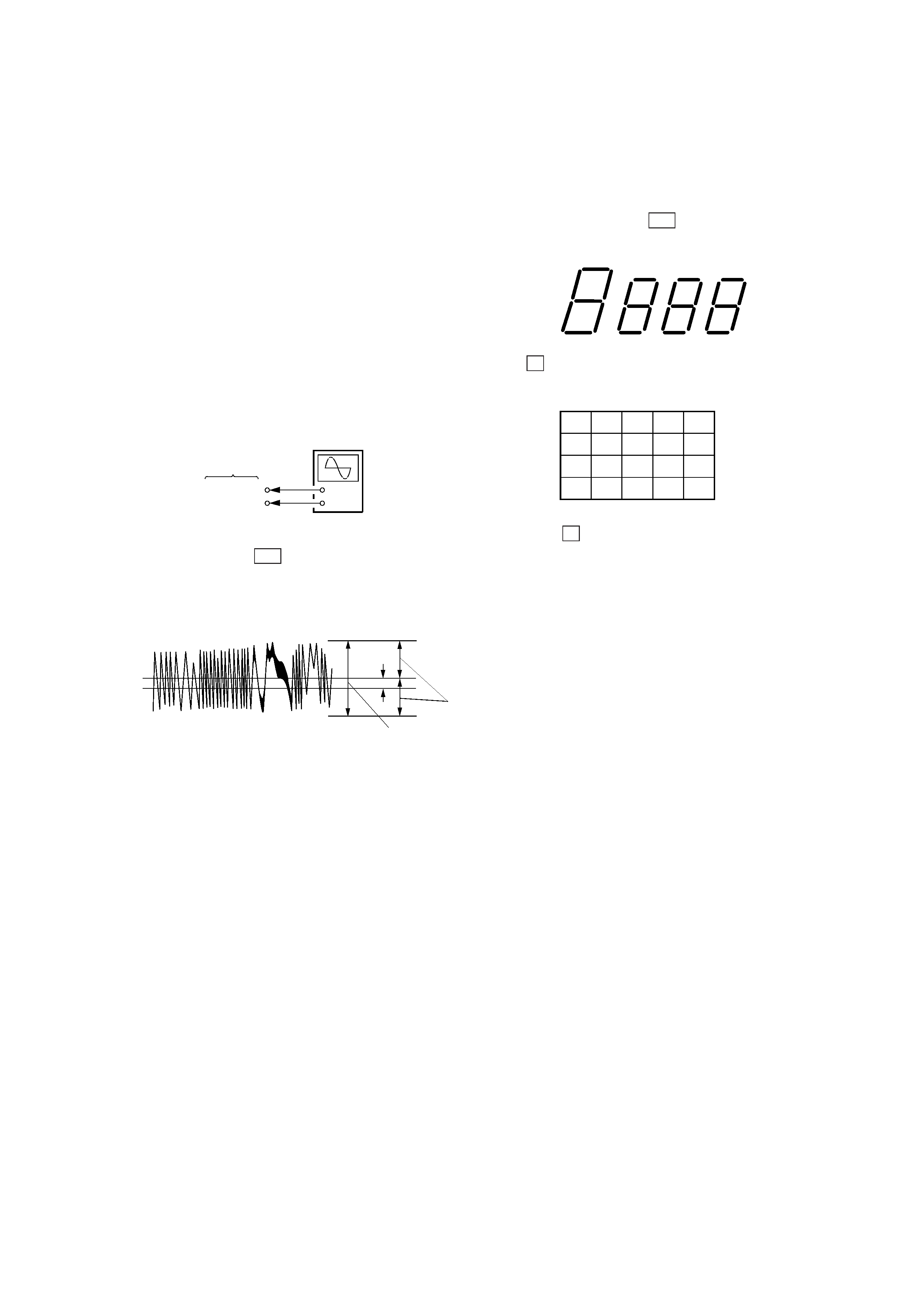
3) Connect an oscilloscope to TP (TE: CN108 1 pin).
4) Insert the test disc (YEDS-18), turn on POWER switch, and
play fifth music with
· (PLAY) and AMS Keys on the
Remocon.
5) Adjust RV101 so that the waveform on oscilloscope is verticolly
symmetric with respect to the A [Vdc], and also its level is 1.3 ±
0.6 Vp-p.
At this time, A/B
× 100 = ± 22 (%) or less
6) The auto gain data are written when a lead wire between TP
(ADJ: CN105 3 pin) and GND is removed.
Note: If the POWER switch was turned on without connecting TP
(ADJ) to the GND, auto gain data are not written to the
memory even if a disc is inserted, but the previous data saved
in the memory are used as focus/tracking data.
1-2. AF MODE
With the TP (AFJ: CN105 2 Pin) connected to the GND on Servo
Board, turn on the POWER switch, and the AF mode is activated
and the following checking can be made.
1-2-1. FL tube check
All tubes turn on, then if
· button is pressed, the display will be
as shown below. (Segment ON 1)
(Segment ON 1)
6
16
2
12
8
18
4
14
10
20
(Segment ON 2)
0Vdc
B
A
symmetric
level: 1.3 ± 0.6 Vp-p
IF
P button is pressed, the display will be as shown below. (Seg-
ment ON 2)
+
SERVO board
TP (TE)
TP (VC)
Oscilloscope
If STOP
p is pressed, all tubes turn on again.
4
1-2-2. key check
All buttons are assigned with numbers respectively
If a button is pressed, the number is counted up and the button
number is displayed.
1-2-3. Remocon check
Press
· button on the Remocon, and " · "on FL tube turns
on. If any other buttons are pressed, all tubes will turn off.
1-3. ADJ MODE
With CN105 3 pin connected to 1 pin on the Servo Board, turn
on the POWER switch, and the ADJ mode is activated where the
following operation is executed.
· GFS, even if low continuously during playing, will cause noth-
ing.
· High speed servo is disabled during an access.
· Gain of focus servo and spindle servo is not lowered.
· Manual operation and measurement for servo system are en-
abled. (For detailed operation method, see the button function
table in ADJ mode.)
1-4. CLV-S MODE
Connect TP1(ADJ) to the GND after turning on the POWER
switch, and the spindle servo becomes CLV-S mode during play-
ing.
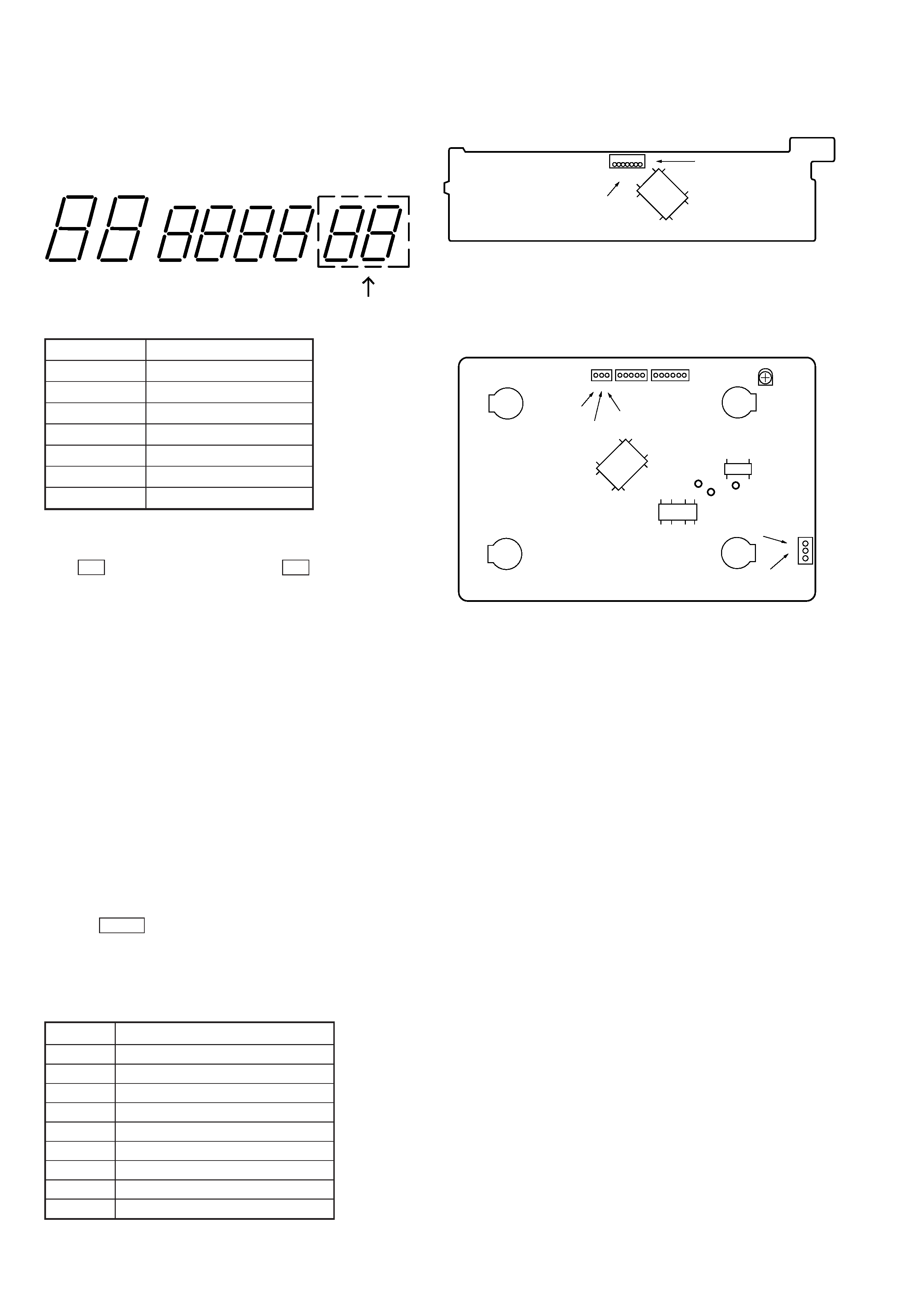
Button function table in ADJ mode
With the TIME key, the jitter value display mode is activated
after all music remaining mode.
The number buttons have the functions as listed below.
Functions of number buttons
(on Remocon attached)
Button number display
Button name Button number display
+
88
=
01
)
02
0
03
PLAY
·
Segment ON 1
P
Segment ON 2
p
All ON
[DISPLAY BOARD] Conductor Side
[SERVO BOARD] Conductor Side
Buttons
Functions
1
Increase focus bias by 8 steps
2
Adjust focus bias to the center
3
Turn off tracking servo and sled servo
4
Initialize auto gain
5
Turn off focus servo
6
Decrease focus bias by 8 steps
7
Readjust focus bias there
8
Turn on tracking servo and sled servo
10
Return auto focus bias to start point
IC105
TP3
RV101
CN108
1
2
IC107
IC106 (TEI)
(TE)
(VC)
CN107
CN105
321CN106
(ADJ)
(AFJ)
(GND)
3
IC801
GND
71
6
IN/OUT SW
CN805
5
SECTION 2
GENERAL
This section is extracted
from instruction manual.