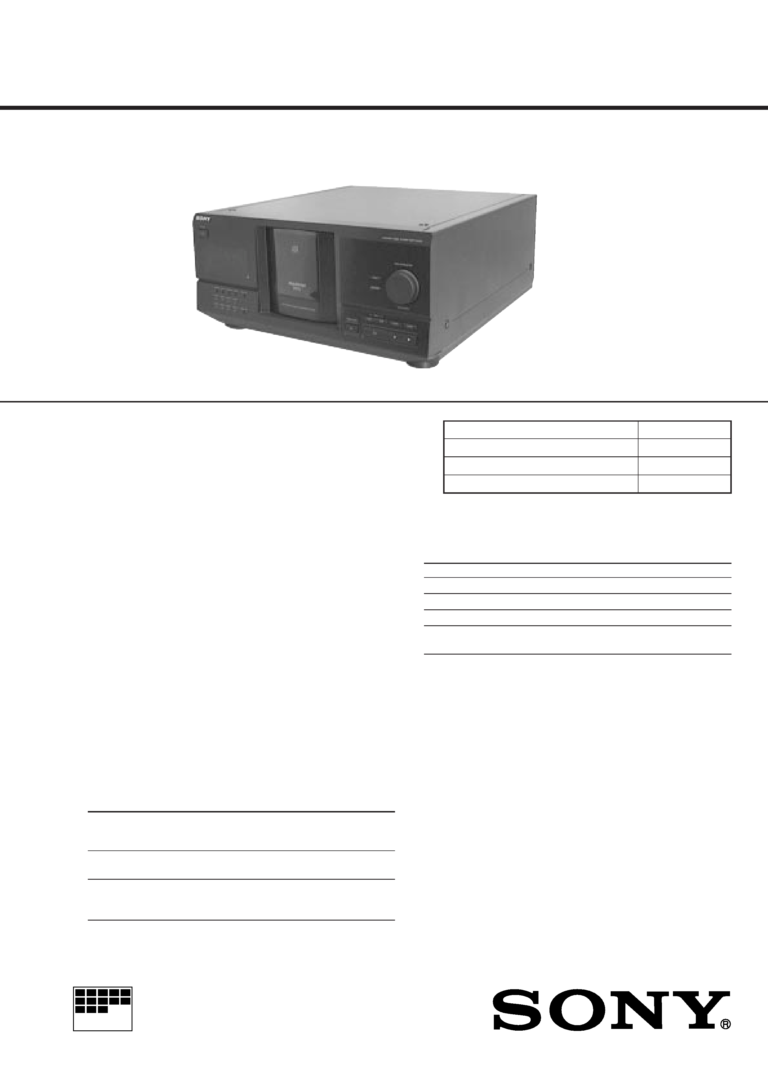
CDP-CX235
US Model
Canadian Model
AEP Model
UK Model
E model
Australian model
SERVICE MANUAL
COMPACT DISC PLAYER
· CDP-CX235 is similar to the earlier CDP-CX220 model.
· CDP-CX235(EA) is similar to the earlier CDP-CX220(E) model.
· CDP-CX235(MY) is similar to the earlier CDP-CX220(SP) model.
· Refer to CDP-CX220 service manual (9-922-819-XX) for
information not contained in this service manual.
Part No.
Description
Remark
***EXPLODED VIEWS***
49
1
X-4949-616-1 DOOR (CD) ASSY
3
X-4949-618-1 PANEL ASSY, FRONT (US, CND)
3
X-4949-619-1 PANEL ASSY, FRONT (EXCEPT, US, CND)
10
3-363-099-01 SCREW (CASE3 TP2)
62
! 1-575-042-21 CORD, POWER (US, CND)
62
! 1-575-651-21 CORD, POWER (AEP, UK, AED, SP)
62
! 1-696-027-11 CORD, POWER (E)
62
! 1-696-845-11 CORD, POWER (AUS)
63
! 1-569-007-11 ADAPTER, CONVERSION 2P (E)
65
* 4-998-525-01 PANEL, BACK (US)
50
65
* 4-998-525-11 PANEL, BACK (CND)
65
* 4-998-525-21 PANEL, BACK (AEP, UK)
65
65
* 4-998-525-41 PANEL, BACK (SP)
65
* 4-998-525-51 PANEL, BACK (E)
65
* 4-998-525-61 PANEL, BACK (AUS)
65
Page Ref.No.
CDP-CX220
CDP-CX235
Part No.
Description
Remark
***EXPLODED VIEWS***
X-4950-812-1 DOOR (CD) ASSY
X-4952-378-1 PANEL ASSY, FRONT (US, CND)
X-4952-379-1 PANEL ASSY,FRONT (E, AEP, UK, MY, SP, EA, AUS)
4-210-291-01 SCREW (CASE 3 TP2)
! 1-783-531-31 CORD, POWER (US, CND)
! 1-575-651-21 CORD, POWER (AEP, UK, MY, SP, EA)
! 1-558-943-41 CORD, POWER (E)
! 1-696-845-11 CORD, POWER (AUS)
! 1-569-008-21 ADAPTOR, CONVERSION 2P (EA)
* 4-225-205-01 PANEL, BACK (US)
* 4-225-205-11 PANEL, BACK (CND)
* 4-225-205-21 PANEL, BACK (AEP)
* 4-225-205-31 PANEL, BACK (UK)
* 4-225-205-61 PANEL, BACK (SP, MY)
* 4-225-205-71 PANEL, BACK (E)
* 4-225-205-41 PANEL, BACK (AUS)
* 4-225-205-52 PANEL, BACK (EA)
· Continue to next page.
· Abbeviation
CND : Canadian model
SP
: Singapore model
MY
: Malaysia model
EA : Saudi Arabia model
AUS : Australian model
Sony Corporation
Home Audio Division Company
2000B1685-1
Printed in Japan ©2000.2
Published by Quality Assurance Dept.
Items marked "*" are not stocked since they are seldom
required for routine service.
Some delay should be anticipated when ordering these
items.
Part No.
Description
Remark
***ELECTRICAL PARTS LIST***
***MISCELLANEOUS***
62
! 1-575-042-21 CORD, POWER (US, CND)
62
! 1-575-651-21 CORD, POWER (AEP, UK, AED, SP)
62
! 1-696-027-11 CORD, POWER (E)
62
! 1-696-845-11 CORD, POWER (AUS)
63
! 1-569-007-11 ADAPTER, CONVERSION 2P (E)
***ACCESSORIES & PACKING MATERIALS***
1-475-654-11 REMOTE COMMANDER (RM-DX220)
3-810-765-11 MANUAL, COMMONNESS INSTRUCTION
(ENGLISH)(US, AUS)
3-810-765-21 MANUAL, COMMONNESS INSTRUCTION
(ENGLISH, FRENCH, GERMAN, SPANISH,
DUTCH, SWEDISH, ITALIAN, PORTUGUESE,
CHINESE)(CND, UK, AED, E, SP)
3-862-563-11 MANUAL, INSTRUCTION
(ENGLISH)(US, AUS)
3-862-563-21 MANUAL, INSTRUCTION (ENGLISH,
FRENCH, SPANISH)
(CND, AEP, UK, E, SP)
3-862-563-31 MANUAL, INSTRUCTION (GERMAN,
DUTCH, ITALIAN,PORTUGUESE)(AEP, UK)
3-862-563-41 MANUAL, INSTRUCTION
(SWEDISH, DANISH, FINNISH)(AED)
3-862-563-51 MANUAL, INSTRUCTION (CHINESE)(E, SP)
9-929-080-11
Page Ref.No.
CDP-CX220
CDP-CX235
The components identified by
mark
! or dotted line with
mark
! are critical for safety.
Replace only with part num-
ber specified.
Les composants identifiés par une
marque
! sont critiques pour la
sécurité.
Ne les remplacer que par une pièce
portant le numéro spécifié.
-- 2 --
Part No.
Description
Remark
***ELECTRICAL PARTS LIST***
***MISCELLANEOUS***
! 1-783-531-31 CORD, POWER (US, CND)
! 1-575-651-21 CORD, POWER (AEP, UK, MY, SP, EA)
! 1-558-943-41 CORD, POWER (E)
! 1-696-845-11 CORD, POWER (AUS)
! 1-569-008-21 ADAPTOR, CONVERSION 2P (EA)
***ACCESSORIES & PACKING MATERIALS***
1-473-801-11 REMOTE COMMANDER (RM-DX250)(E)
1-475-654-11 REMOTE COMMANDER (RM-DX220)
(EXCEPT E)
3-866-670-11 MANUAL, COMMONNESS INSTRUCTION
(ENGLISH)(US, UK, AUS)
3-866-670-21 MANUAL, COMMONNESS INSTRUCTION
(ENGLISH, FRENCH, GERMAN, SPANISH,
DUTCH, PORTUGUESE, SWEDISH, ITALIAN,
CHINESE)(E, CND, AEP, MY, SP)
3-866-670-41 MANUAL, COMMONNESS INSTRUCTION
(ENGLISH, ARABIC, CHINESE)(EA)
4-226-586-11 MANUAL, INSTRUCTION
(ENGLISH)(US, AUS)
4-226-586-21 MANUAL, INSTRUCTION (ENGLISH, FRENCH,
SPANISH, SWEDISH)
(E, CND, AEP, UK, MY, SP, EA)
4-226-586-31 MANUAL, INSTRUCTION (GERMAN, FRENCH,
ITALIAN, PORTUGUESE)(AEP)
4-226-586-41 MANUAL, INSTRUCTION (CHINESE)(E, MY, SP)
4-226-586-51 MANUAL, INSTRUCTION (ARABIC)(EA)
MICROFILM
SERVICE MANUAL
COMPACT DISC PLAYER
US Model
Canadian Model
AEP Model
UK Model
E Model
Australian Model
Compact disc player
Laser
Semiconductor laser (
= 780 nm)
Emission duration: continuous
Laser output
Max 44.6 µW*
* This output is the value measured at
a distance of 200 mm from the
objective lens surface on the
Optical Pick-up block with 7 mm
aperture.
Frequency response
20 Hz to 20 kHz ± 0.5 dB
Signal-to-noise ratio
More than 105 dB
Dynamic range
More than 98 dB
Harmonic distortion
Less than 0.0045%
Channel separation
More than 97 dB
Outputs
SPECIFICATIONS
CDP-CX220
Model Name Using Similar Mechanism
CDP-CX250
CD Mechanism Type
CDM-40B
Base Unit Type
KSM-213BKN/M-N
Optical Pick-up Type
KSS-213B/S-N
Jack
Maximum
Load impedance
type
output
level
LINE OUT
Phono
2V
Over 10 kilohms
Jacks
(at 50 kilohms)
DIGITAL
Optical
18 dBm
Wave length: 660 nm
OUT
output
(OPTICAL)
connector
Where purchased
Power requirements
USA/Canada
120 V AC, 60 Hz
Australia
240 V AC, 50/60 Hz
Europe
220 V 230 V AC, 50/60 Hz
Other countries
110 V 120 V or 220 V 240 V AC,
adjustable, 50/60 Hz
General
Power requirements
Power consumption
12 W
Dimensions (approx.)
When the front cover is closed
(w/h/d)
430
× 200 × 480 mm (17 × 7 7/8 × 19 in.)
incl. projecting parts
Mass (approx.)
9.5 kg (21 lbs)
Supplied accessories
Audio cord (2 phono plugs 2 phono plugs) (1)
Remote commander (remote) (1)
Sony SUM-3 (NS) batteries (2)
CD booklet holders (2) and label (1)
Design and specifications are subject to change without notice.
2
TABLE OF CONTENTS
1.
SERVICING NOTES ............................................... 3
2.
GENERAL ................................................................... 6
3.
DISASSEMBLY ......................................................... 7
4.
TEST MODE .............................................................. 10
5.
MECHANICAL ADJUSTMENTS ....................... 13
6.
ELECTRICAL ADJUSTMENTS ......................... 19
7.
DIAGRAMS ................................................................. 22
7-1. Note for Printed Wiring Boards and
Schematic Diagrams ....................................................... 23
7-2. Printed Wiring Board BD Section ........................... 25
7-3. Schematic Diagram BD Section ............................... 27
7-4. Printed Wiring Board Main Section ........................ 29
7-5. Schematic Diagram Main Section ........................... 31
7-6. Printed Wiring Boards Jack Section ........................ 33
7-7. Schematic Diagram Jack Section ............................ 35
7-8. Printed Wiring Boards Panel Section ...................... 37
7-9. Schematic Diagram Panel Section .......................... 39
7-10. Printed Wiring Board Sensor/Motor Section .......... 41
7-11. Schematic Diagram Sensor/Motor Section ............. 43
7-12. IC Pin Function Description ........................................... 47
8.
EXPLODED VIEWS ................................................ 49
9.
ELECTRICAL PARTS LIST ............................... 56
CAUTION
Use of controls or adjustments or performance of procedures
other than those specified herein may result in hazardous
radiation exposure.
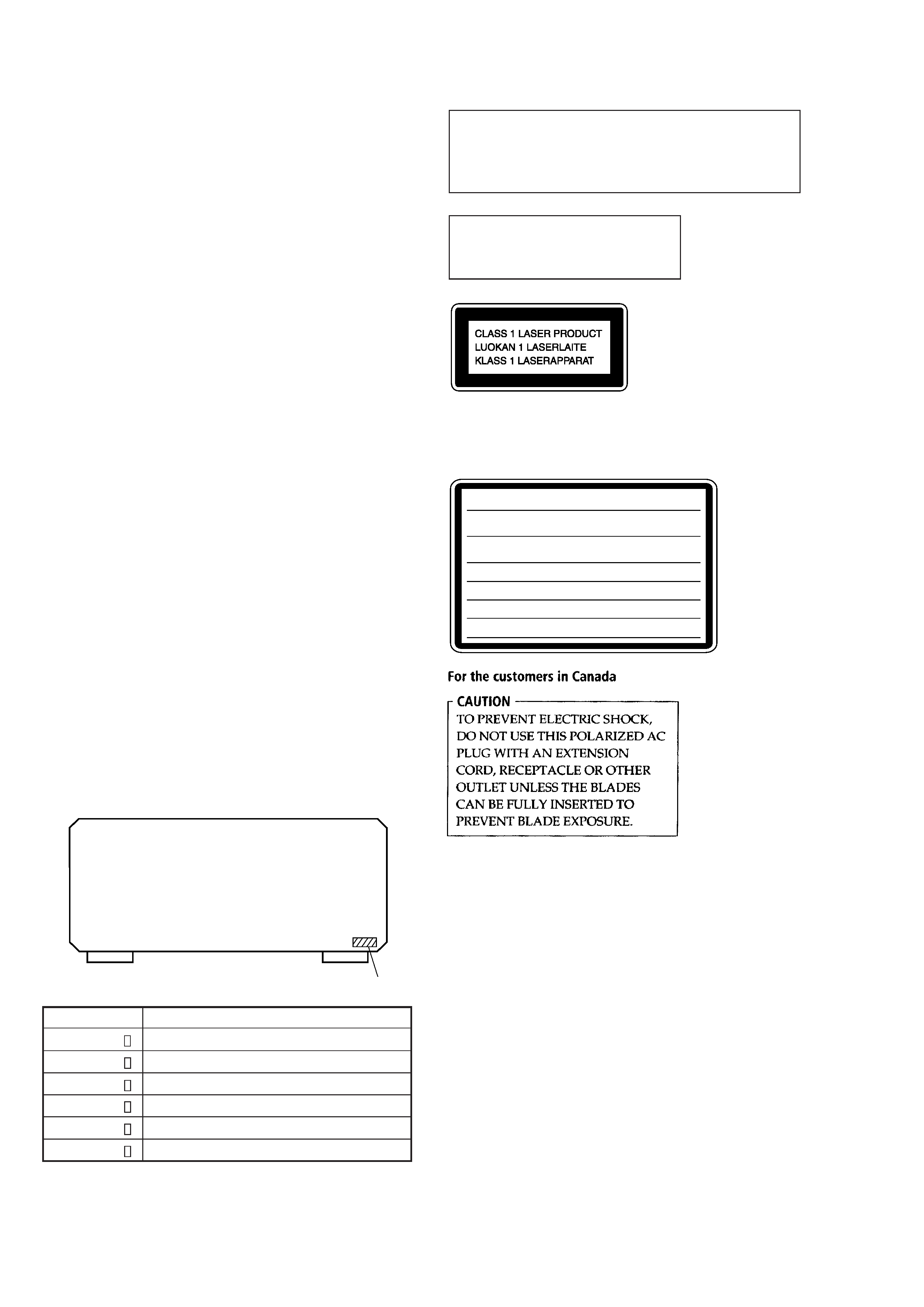
The laser component in this product
is capable of emitting radiation
exceeding the limit for Class 1.
This appliance is classified as
a CLASS 1 LASER product.
The CLASS 1 LASER
PRODUCT MARKING is
located on the rear exterior.
4-998-525-0
4-998-525-1
4-998-525-2
4-998-525-4
4-998-525-5
4-998-525-6
US model
Canadian model
AEP, AED UK model
Singapore model
E model
Australian model
PART No.
MODEL
MODEL IDENTIFICATION
-- BACK PANEL --
· Abbreviation
AED: North European
CAUTION
: INVISIBLE LASER RADIATION WHEN OPEN AND
INTERLOCKS DEFEATED.
AVOID EXPOSURE TO BEAM.
ADVARSEL : USYNLIG LASERSTRÅLING VED ÅBNING NÅR
SIKKERHEDSAFBRYDERE ER UDE AF FUNKTION. UNDGÅ UDSAETTELSE
FOR STRÅLING.
VORSICHT : UNSICHTBARE LASERSTRAHLUNG, WENN
ABDECKUNG GEÖFFNET UND SICHEREITSVERRIEGELUNG
ÜBERBRÜCKT. NICHT DEM STRAHL AUSSETZEN.
VARO
!
: AVATTAESSA JA SUOJALUKITUS OHITETTAESSA OLET ALT-
TIINA NÄKYMÄTTÖMÄLLE LASERSÄTEILYLLE. ÄLÄ KATSO SÄTEESEEN.
VARNING
: OSYNLING LASERSTRÅLING NÄR DENNA DEL ÄR ÖPPNAD
OCH SPÄRREN ÄR URKOPPLAD. BETRAKTA EJ STRÅLEN.
ADVERSEL : USYNLIG LASERSTRÅLING NÅR DEKSEL ÅPNES OG
SIKKERHEDSLÅS BRYTES. UNNGÅ EKSPONERING FOR STRÅLEN.
VIGYAZAT
! : A BURKOLAT NYITÁSAKOR LÁTHATATLAN LÉZERSU-
GÁRVESZÉLY
! KERÜLJE A BESUGÁRZÁST!
(Except for the customers in the United States and
Canada)
The following caution label is located inside the unit.
PART No.
3
ATTENTION AU COMPOSANT AYANT RAPPORT
À LA SÉCURITÉ!
LES COMPOSANTS IDENTIFIÉS PAR UNE MARQUE
!
SUR LES DIAGRAMMES SCHÉMATIQUES ET LA LISTE
DES PIÈCES SONT CRITIQUES POUR LA SÉCURITÉ
DE FONCTIONNEMENT. NE REMPLACER CES COM-
POSANTS QUE PAR DES PIÈCES SONY DONT LES
NUMÉROS SONT DONNÉS DANS CE MANUEL OU
DANS LES SUPPLÉMENTS PUBLIÉS PAR SONY.
SAFETY-RELATED COMPONENT WARNING!!
COMPONENTS IDENTIFIED BY MARK
! OR DOTTED
LINE WITH MARK
! ON THE SCHEMATIC DIAGRAMS
AND IN THE PARTS LIST ARE CRITICAL TO SAFE
OPERATION. REPLACE THESE COMPONENTS WITH
SONY PARTS WHOSE PART NUMBERS APPEAR AS
SHOWN IN THIS MANUAL OR IN SUPPLEMENTS PUB-
LISHED BY SONY.
SAFETY CHECK-OUT
After correcting the original service problem, perform the follow-
ing safety check before releasing the set to the customer:
Check the antenna terminals, metal trim, "metallized" knobs,
screws, and all other exposed metal parts for AC leakage.
Check leakage as described below.
LEAKAGE
The AC leakage from any exposed metal part to earth ground and
from all exposed metal parts to any exposed metal part having a
return to chassis, must not exceed 0.5 mA (500 microampers.).
Leakage current can be measured by any one of three methods.
1. A commercial leakage tester, such as the Simpson 229 or RCA
WT-540A. Follow the manufacturers' instructions to use these
instruments.
2. A battery-operated AC milliammeter. The Data Precision 245
digital multimeter is suitable for this job.
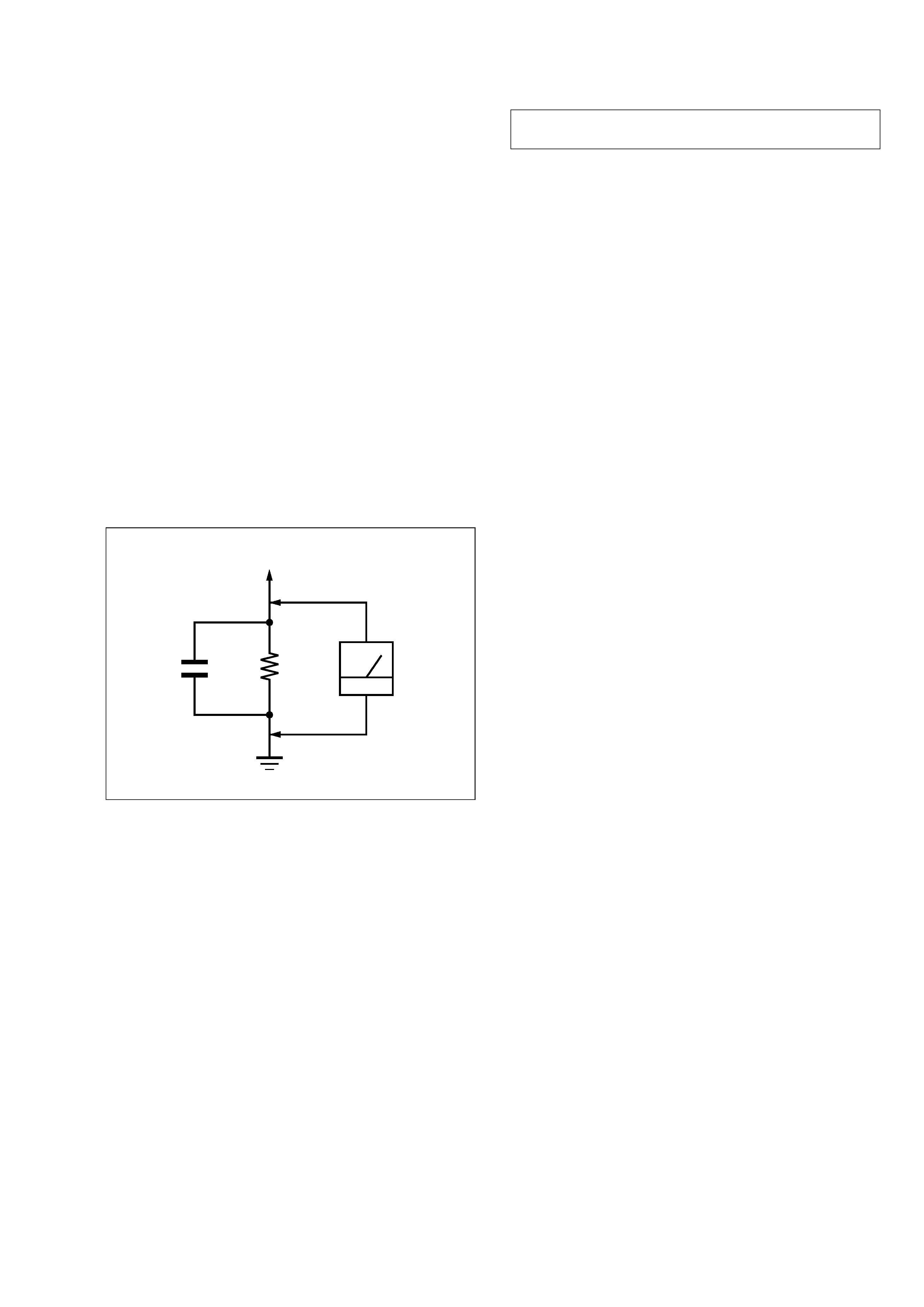
3. Measuring the voltage drop across a resistor by means of a
VOM or battery-operated AC voltmeter. The "limit" indica-
tion is 0.75 V, so analog meters must have an accurate low-
voltage scale. The Simpson 250 and Sanwa SH-63Trd are ex-
amples of a passive VOM that is suitable. Nearly all battery
operated digital multimeters that have a 2 V AC range are suit-
able. (See Fig. A)
Fig. A.
Using an AC voltmeter to check AC leakage.
1.5 k
0.15
µF
AC
voltmeter
(0.75 V)
To Exposed Metal
Parts on Set
Earth Ground
SECTION 1
SERVICING NOTES
The laser diode in the optical pick-up block may suffer electro-
static break-down because of the potential difference generated
by the charged electrostatic load, etc. on clothing and the human
body.
During repair, pay attention to electrostatic break-down and also
use the procedure in the printed matter which is included in the
repair parts.
The flexible board is easily damaged and should be handled with
care.
NOTES ON LASER DIODE EMISSION CHECK
The laser beam on this model is concentrated so as to be focused
on the disc reflective surface by the objective lens in the optical
pick-up block. Therefore, when checking the laser diode emis-
sion, observe from more than 30 cm away from the objective lens.
LASER DIODE AND FOCUS SEARCH OPERATION
CHECK
Carry out the "S curve check" in "CD section adjustment" and
check that the S curve waveform is output repeatedly.
NOTES ON HANDLING THE OPTICAL PICK-UP
BLOCK OR BASE UNIT