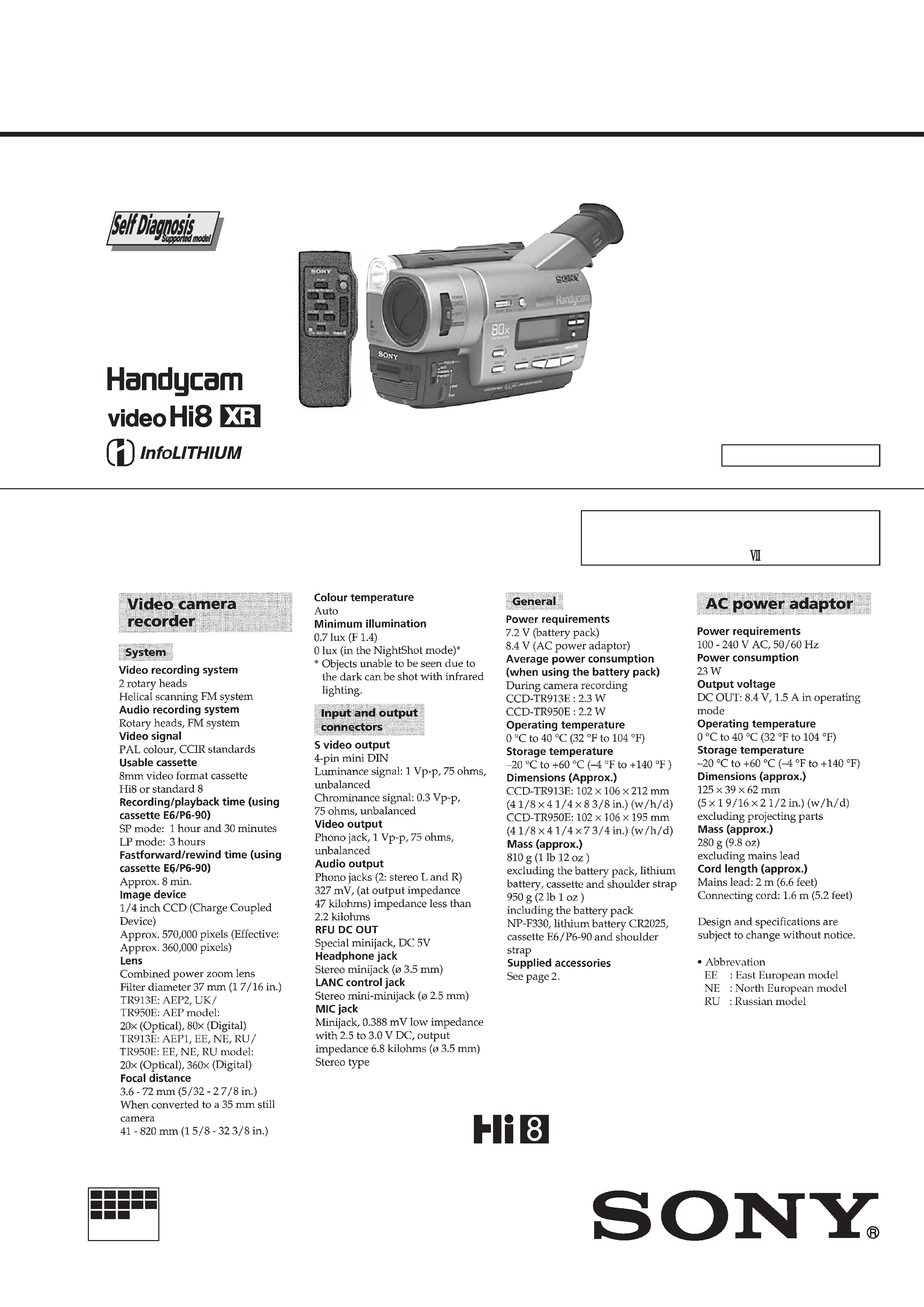
CCD-TR913E/TR950E
RMT-708
SERVICE MANUAL
VIDEO CAMERA RECORDER
MICROFILM
B501 MECHANISM
Photo: CCD-TR950E
SPECIFICATIONS
For MECHANISM ADJUSTMENT, refer to
the "8mm Video MECHANICAL
ADJUSTMENT MANUAL
" (9-973-801-11).
AEP Model
North European Model
East European Model
Russian Model
CCD-TR913E/TR950E
UK Model
CCD-TR913E
Ver 1.2 2001.01
-- 2 --
SAFETY-RELATED COMPONENT WARNING!!
COMPONENTS IDENTIFIED BY MARK
! OR DOTTED LINE WITH
MARK
! ON THE SCHEMATIC DIAGRAMS AND IN THE PARTS
LIST ARE CRITICAL TO SAFE OPERATION. REPLACE THESE
COMPONENTS WITH SONY PARTS WHOSE PART NUMBERS
APPEAR AS SHOWN IN THIS MANUAL OR IN SUPPLEMENTS
PUBLISHED BY SONY.
1.
Check the area of your repair for unsoldered or poorly-soldered
connections. Check the entire board surface for solder splashes
and bridges.
2.
Check the interboard wiring to ensure that no wires are
"pinched" or contact high-wattage resistors.
3.
Look for unauthorized replacement parts, particularly
transistors, that were installed during a previous repair. Point
them out to the customer and recommend their replacement.
4.
Look for parts which, through functioning, show obvious signs
of deterioration. Point them out to the customer and
recommend their replacement.
5.
Check the B+ voltage to see it is at the values specified.
6.
Flexible Circuit Board Repairing
· Keep the temperature of the soldering iron around 270°C
during repairing.
· Do not touch the soldering iron on the same conductor of the
circuit board (within 3 times).
· Be careful not to apply force on the conductor when soldering
or unsoldering.
SAFETY CHECK-OUT
After correcting the original service problem, perform the following
safety checks before releasing the set to the customer.
Model
Destination
Lens
Optical
Digital
Color EVF
B/W EVF
CCD-TR913E
AEP1, AEP2, UK, NE,
EE, RU
20
×
80
× (Note)
!
®
CCD-TR950E
AEP, NE, EE, RU
20
×
80
× (Note)
®
!
Remark
® : With VF-126 board
® : With VF-129 board
Table for difference of function
Note : AEP1, EE, NE, RU model is 360
×.
·
Abbreviation
NE : North European Model
EE
: East European Model
RU : Russian Model
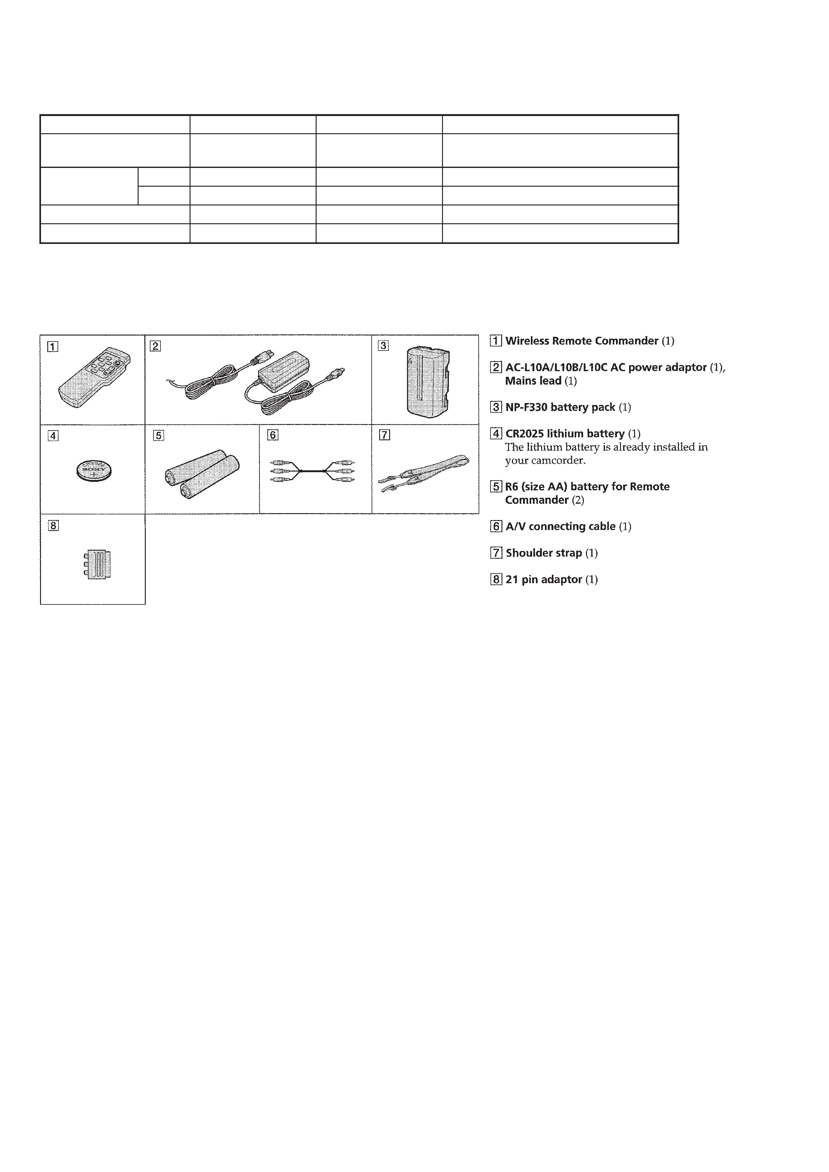
Supplied accessories

-- 3 --
TABLE OF CONTENTS
SERVICE NOTE
1.
POWER SUPPLY DURING REPAIRS ····························· 6
2.
TO TAKE OUT A CASSETTE WHEN NOT EJECT
(FORCE EJECT) ································································ 6
SELF-DIAGNOSIS FUNCTION
1.
Self-diagnosis Function ······················································ 7
2.
Self-diagnosis Display ························································ 7
3.
Service Mode Display ························································ 7
3-1.
Display Method ·································································· 7
3-2.
Switching of Backup No. ··················································· 7
3-3.
End of Display ···································································· 7
4.
Self-diagnosis Code Table ·················································· 8
1.
GENERAL
Checking supplied accessories ·················································· 1-1
Quick Start Guide ······································································ 1-1
1. Connecting the mains lead ················································· 1-1
2. Inserting a cassette ····························································· 1-1
3. Recording a picture ···························································· 1-1
4. Monitoring the playback picture in the viewfinder ··········· 1-1
Getting Started ··········································································· 1-1
Using this manual ·································································· 1-1
Step 1 Preparing the power supply ········································ 1-2
Step 2 Inserting a cassette ······················································ 1-3
Recording Basics ···································································· 1-4
Recording a picture ································································ 1-4
Checking the recording EDITSEARCH/Rec Review ········ 1-6
Playback Basics ······································································ 1-6
Connections for playback ······················································ 1-6
Playing back a tape ································································ 1-7
Advanced Recording Operations ··············································· 1-8
Photo recording ······································································ 1-8
Using the wide mode ····························································· 1-8
Using the fader function ························································ 1-9
Using special effects Picture effect ····································· 1-9
Using special effects Digital effect ··································· 1-10
Using the PROGRAM AE function ····································· 1-11
Adjusting the exposure manually ········································ 1-11
Focusing manually ······························································· 1-12
Superimposing a title ··························································· 1-12
Making your own titles ························································ 1-13
Using the built-in light ························································· 1-13
Advanced Playback Operations ··············································· 1-14
Playing back a tape with digital effects ······························· 1-14
Editing on Other Equipment ···················································· 1-14
Dubbing a tape ····································································· 1-14
Customizing Your Camcorder ················································· 1-15
Changing the MENU settings ·············································· 1-15
Resetting the date and time ·················································· 1-16
Additional Information ···························································· 1-17
Usable cassettes and playback modes ·································· 1-17
Changing the lithium battery in your camcorder ················· 1-17
Troubleshooting ··································································· 1-18
Self-diagnosis display ·························································· 1-19
Warning indicators and messages ········································ 1-19
Using your camcorder abroad ·············································· 1-19
Maintenance information and precautions ··························· 1-19
Quick Reference ······································································ 1-21
Identifying the parts and controls ········································ 1-21
Quick function guide ··························································· 1-23
2.
DISASSEMBLY
2-1.
Cabinet (R) Assembly (TR913E), (TR950E) ·················· 2-2
2-2.
Mechanism Deck ····························································· 2-3
2-3.
Color EVF Block, VF-126 Board (TR950E) ··················· 2-4
2-4.
B/W EVF Block, VF-129 Board (TR913E) ···················· 2-5
2-5.
Lens Block ······································································· 2-6
2-6.
Mechanism Deck, VC-214, DD-117 Boards ··················· 2-7
2-7.
Video Light ······································································ 2-9
2-8.
CF-58 Board (TR913E) ··················································· 2-9
CF-58 Board (TR950E) ··················································· 2-9
2-9.
How to Identify Drum and Note ···································· 2-10
2-10. Circuit Boards Location ················································ 2-11
2-11. Flexible Boards Location ·············································· 2-12
3.
BLOCK DIAGRAMS
3-1.
Overall Block Diagram ··················································· 3-1
3-2.
Camera/Video Block Diagram ········································ 3-5
3-3.
VTR/Camera Control Block Diagram ····························· 3-9
3-4.
Servo Block Diagram ···················································· 3-12
3-5.
Mode Control Block Diagram ······································· 3-15
3-6.
Audio Block Diagram ··················································· 3-19
3-7.
Color EVF Block Diagram (CCD-TR950E) ················· 3-23
3-8.
B/W EVF Block Diagram (CCD-TR913E) ··················· 3-27
3-9.
Power Block Diagram ··················································· 3-29
4.
PRINTED WIRING BOARDS AND
SCHEMATIC DIAGRAMS
4-1.
Frame Schematic Diagram-1 ··········································· 4-1
Frame Schematic Diagram-2 ··········································· 4-4
4-2.
Printed Wiring Boards and Schematic Diagrams ············ 4-7
· CD-209 (CCD Imager)
Printed Wiring Board and
Schematic Diagram ········································· 4-8
· VC-214 (Camera Processor, Y/C Processor, Focus/Zoom
Motor Drive, REC/PB Head AMP, Video/Interface, IR,
Mode Control, Servo, System Control,Audio Processor)
Printed Wiring Board ···································· 4-11
· VC-214 (Camera Processor)(1/10)
Schematic Diagram ....................................... 4-17
· VC-214 (Y/C Processor)(2/10)
Schematic Diagram ······································· 4-19
· VC-214 (Focus/Zoom Motor Drive)(3/10)
Schematic Diagram ······································· 4-25
· VC-214 (REC/PB Head AMP)(4/10)
Schematic Diagram ······································· 4-27
· VC-214 (Video/Interface)(5/10)
Schematic Diagram ······································· 4-30
· VC-214 (IR Transmitter)(6/10)
Schematic Diagram ······································· 4-33
· VC-214 (Mode Control)(7/10)
Schematic Diagram ······································· 4-36
· VC-214 (Servo)(8/10)
Schematic Diagram ······································· 4-39
· FP-249 (S/T Reel Sensor), FP-356 (Top Sensor),
FP-355 (Tape LED) Flexible Board ···························· 4-42
· VL-25 (Video Light)
Printed Wiring Board ···································· 4-43
· VC-214 (HI Control)(9/10)
Schematic Diagram ······································· 4-44
· VC-214 (Audio)(10/10)
Schematic Diagram ······································· 4-47
· SE-85 (Steady Shot), PJ-94 (AV IN/OUT)
Printed Wiring Boards ··································· 4-50
· SE-85 (Steady Shot), PJ-94 (AV IN/OUT)
Schematic Diagrams ····································· 4-53
· MA-353 (Stereo MIC AMP, Laser Link)
Printed Wiring Board ···································· 4-55
· MA-353 (Stereo MIC AMP, Laser Link)
Schematic Diagram ······································· 4-57
· VF-126 (Color EVF)
Printed Wiring Board ···································· 4-61

-- 4 --
· VF-126 (Color EVF)
Schematic Diagram ······································· 4-63
· FK-8500, SS-8500 (Control Switch Block)
Schematic Diagram ······································· 4-68
· VF-129 (B/W EVF)
Printed Wiring Board and
Schematic Diagram ....................................... 4-69
· CF-58 (User Control)
Printed Wiring Board .................................... 4-72
· CF-58 (User Control)
Schematic Diagram ······································· 4-75
· DD-117 (DC/DC Converter)
Printed Wiring Board ···································· 4-79
· DD-117 (DC/DC Converter)
Schematic Diagram ······································· 4-81
5.
ADJUSTMENTS
5-1.
CAMERA SECTION ADJUSTMENT ··························· 5-1
1-1.
Preparations before Adjustment (Camera Section) ········· 5-1
1-1-1. List of Service Tools ························································ 5-1
1-1-2. Adjusting Items When Replacing Main Parts ················· 5-2
1-1-3. Preparations ····································································· 5-3
1-1-4. Precaution ········································································ 5-5
1.
Setting the Switch ···························································· 5-5
2.
Order of Adjustments ······················································ 5-5
3.
Subjects ··········································································· 5-5
1-2.
Initialization of D, E, F Page Data ·································· 5-6
1.
Initializing the D, E, F Page Data ···································· 5-6
2.
Modification of D, E, F Page Data ·································· 5-6
3.
D Page Table ···································································· 5-6
4.
F Page Table ···································································· 5-7
5.
E Page Table ·································································· 5-10
1-3.
Camera System Adjustments ········································· 5-13
1.
HALL Adjustment ························································· 5-13
2.
Flange Back Adjustment ··············································· 5-13
2-1.
Flange Back Adjustment (1) ·········································· 5-13
2-2.
Flange Back Adjustment (2) ·········································· 5-14
3.
Flange Back Check ························································ 5-14
4.
Picture Frame Setting ···················································· 5-15
5.
AGC Gain Calibration Adjustment ······························· 5-15
6.
Color Reproduction Adjustment ···································· 5-16
7.
IRIS IN/OUT Adjustment ············································· 5-16
8.
MAX GAIN Adjustment ··············································· 5-17
9.
Auto White Balance Standard Data Input ····················· 5-17
10.
Auto White Balance Adjustment ··································· 5-18
11.
White Balance Check ···················································· 5-19
12.
Angular Velocity Sensor Sensitivity Preset and
Steady Shot Check ························································· 5-20
1-4.
Color Electronic Viewfinder System Adjustment
(CCD-TR950E) ····························································· 5-21
1.
EVF Initial Data Input ··················································· 5-21
2.
VCO Adjustment (VF-126 board) ································· 5-22
3.
Bright Adjustment (VF-126 board) ······························· 5-22
4.
Contrast Adjustment (VF-126 board) ···························· 5-23
5.
Backlight Consumption Current Adjustment
(VF-126 board) ······························································ 5-23
6.
White Balance Adjustment (VF-126 board) ·················· 5-24
1-5.
Monochrome Electronic Viewfinder System
Adjustment (CCD-TR913E) ·········································· 5-25
1-5-1. Horizontal Slant Check ················································· 5-25
1-5-2. Centering Adjustment ···················································· 5-25
1-5-3. Focus Adjustment ·························································· 5-25
1-5-4. Aberration Adjustment ·················································· 5-26
1-5-5. Horizontal Amplitude Adjustment (VF-129 board) ······ 5-26
1-5-6. Vertical Amplitude Adjustment (VF-129 board) ··········· 5-27
1-5-7. Brightness Adjustment (VF-129 Board) ························ 5-27
1-5-8. Horizontal Amplitude, Vertical Amplitude,
Focus Check ·································································· 5-27
5-2.
MECHANISM SECTION ADJUSTMENT ·················· 5-28
2-1.
Operating Without Cassette ··········································· 5-28
2-2.
Tape Path Adjustment ···················································· 5-28
5-3.
VIDEO SECTION ADJUSTMENT ······························ 5-29
3-1.
Preparations Before Adjustments ·································· 5-29
3-1-1. Equipment to Required ·················································· 5-29
3-1-2. Precautions on Adjusting ··············································· 5-30
3-1-3. Adjusting Connectors ···················································· 5-30
3-1-4. Connecting the Equipments ··········································· 5-31
3-1-5. Alignment Tape ····························································· 5-32
3-1-6. Output Level and Impedance ········································· 5-32
3-1-7. Recording Mode (Standard 8/Hi8) Switching ··············· 5-32
3-2.
System Control System Adjustment ······························ 5-33
1.
Initialization of D, E, F Page Data ································ 5-33
2.
Battery End Adjustment (VC-214 board) ······················ 5-33
3-3.
Servo System Adjustments ············································ 5-34
1.
CAP FG Offset Adjustment (VC-214 board) ················ 5-34
2.
Switching Position Adjustment (VC-214 board) ··········· 5-34
3-4.
Video System Adjustments ············································ 5-35
1.
28 MHz Origin Oscillation Adjustment
(VC-214 board) ····························································· 5-35
2.
AFC f0 Adjustment (VC-214 board) ······························ 5-35
3.
Filter f0 Adjustment (VC-214 board) ····························· 5-36
4.
Y OUT Level Adjustment (VC-214 board) ··················· 5-36
5.
C OUT Level Adjustment (VC-214 board) ··················· 5-37
6.
RP Filter f0 Adjustment (VC-214 board) ······················· 5-37
7.
REC Y Current Adjustment (VC-214 board) ················ 5-38
8.
REC L Level Adjustment (VC-214 board) ···················· 5-39
9.
REC C Current Adjustment (VC-214 board) ················ 5-40
3-5.
IR Transmitter Adjustments ··········································· 5-41
1.
IR Video Carrier Frequency Adjustment
(VC-214 board) ····························································· 5-41
2.
IR Video Deviation Adjustment (VC-214 board) ·········· 5-41
3.
IR Audio Deviation Adjustment (VC-214 board) ········· 5-42
3-6.
Audio System Adjustment ············································· 5-43
1.
1.5 MHz Deviation Adjustment (VC-214 board) ·········· 5-44
2.
1.7 MHz Deviation Adjustment (VC-214 board) ·········· 5-45
3.
BPF f0 Adjustment (VC-214 board) ······························ 5-46
5-4.
SERVICE MODE ·························································· 5-47
4-1.
Adjustment Remote Commander ·································· 5-47
1.
Using the Adjustment Remote Commander ·················· 5-47
2.
Precautions Upon Using the Adjustment Remote
Commander ··································································· 5-47
4-2.
Data Process ·································································· 5-48
4-3.
Service Mode ································································· 5-49
1.
Test Mode Setting ·························································· 5-49
2.
Emergency Memory Address ········································ 5-50
2-1.
EMG Code (Emergency Code) ····································· 5-50
2-2.
MSW Codes ·································································· 5-51
3.
Bit Value Discrimination ··············································· 5-52
4.
Input/Output Selection Check ······································· 5-52
5.
LED, LCD (Display Window) Check ··························· 5-52
6.
Record of Use Check ····················································· 5-53
7.
Switch Check (1) ··························································· 5-53
8.
Switch Check (2) ··························································· 5-54
9.
Headphone Jack Check ················································· 5-54
6.
REPAIR PARTS LIST
6-1.
Exploded Views ······························································· 6-1
6-1-1. Front Panel (D) Block and Battery Panel (P) Block
Assembly ········································································· 6-1
6-1-2. Cabinet (R) Block Assembly ··········································· 6-2
6-1-3. Cabinet (L) Block and Main Boards Assembly ··············· 6-3
6-1-4. EVF Block Assembly ······················································ 6-4

-- 5 --
* The color reproduction frame is shown on page 251.
6-1-5. Zoom Lens (LSV-630A) ·················································· 6-5
6-1-6. Cassette Compartment Assembly ···································· 6-6
6-1-7. LS Chassis Assembly ······················································ 6-7
6-1-8. Mechanism Chassis Assembly ········································ 6-8
6-2.
Electrical Parts List ························································· 6-9