Sony
Corporation
CCD-TRV300E
RMT
-717
SER
VICE
MANUAL
CCD-TRV300E
RMT-717
SERVICE MANUAL
MICROFILM
For MECHANISM ADJUSTMENTS, refer to
the "8mm Video MECHANICAL ADJUSTMENT
MANUAL VII" (9-973-801-11).
SPECIFICATIONS
H
VIDEO CAMERA RECORDER
B MECHANISM
Sony Corporation
Personal A&V Products Company
9-974-057-11
98C0941-1
Printed in Japan © 1998. 3
Published by Quality Engineering Dept.
(Osaki East)
266
CCD-TRV300E
AEP Model

SAFETY-RELATED COMPONENT WARNING !!
COMPONENTS IDENTIFIED BY MARK !OR DOTTED LINE WITH
MARK ! ON THE SCHEMATIC DIAGRAMS AND IN THE PARTS
LIST ARE CRITICAL TO SAFE OPERATION. REPLACE THESE
COMPONENTS WITH SONY PARTS WHOSE PART NUMBERS
APPEAR AS SHOWN IN THIS MANUAL OR IN SUPPLEMENTS
PUBLISHED BY SONY.
1. Check the area of your repair for unsoldered or poorly-soldered
connections. Check the entire board surface for solder splashes
and bridges.
2. Check the interboard wiring to ensure that no wires are "pinched"
or contact high-wattage resistors.
3. Look for unauthorized replacement parts, particularly transistors,
that were installed during a previous repair. Point them out to
the customer and recommend their replacement.
4. Look for parts which, though functioning, show obvious signs
of deterioration. Point them out to the customer and recommend
their replacement.
5. Check the B+ voltage to see it is at the values specified.
6. Flexible Circuit board Repairing
· Keep the temperature of the soldering iron around 270
°C during
repairing.
· Do not touch the soldering iron on the same conductor of the
circuit board (within 3 times).
· Be careful not to apply force on the conductor when soldering
or unsoldering.
SAFETY CHECK-OUT
After correcting the original service problem, perform the following
safety checks before releasing the set to the customer:
2
FOR CAMERA COLOR REPRODUCTION ADJUSTMENT Take a copy CAMERA COLOR REPRODUCTION FRAME
and Parts reference sheets with a clear sheet for use.
CCD-TRV300E

3
Supplied accessories
1 Wireless Remote Commander (1)
2 AC-L10A/L10B/L10C AC power adaptor
3 NP-F330 Battery pack (1)
4 CR2025 Lithium Battery (1)
The lithium battery is already installed in your camcorder.
5 Size AA (R6) battery for Remote Commander (2)
6 A / V connecting cable (1)
7 Shoulder strap (1)
8 21 pin adaptor (1)
9 Lenscap (1)
1
4
8
7
3
2
56
9
4
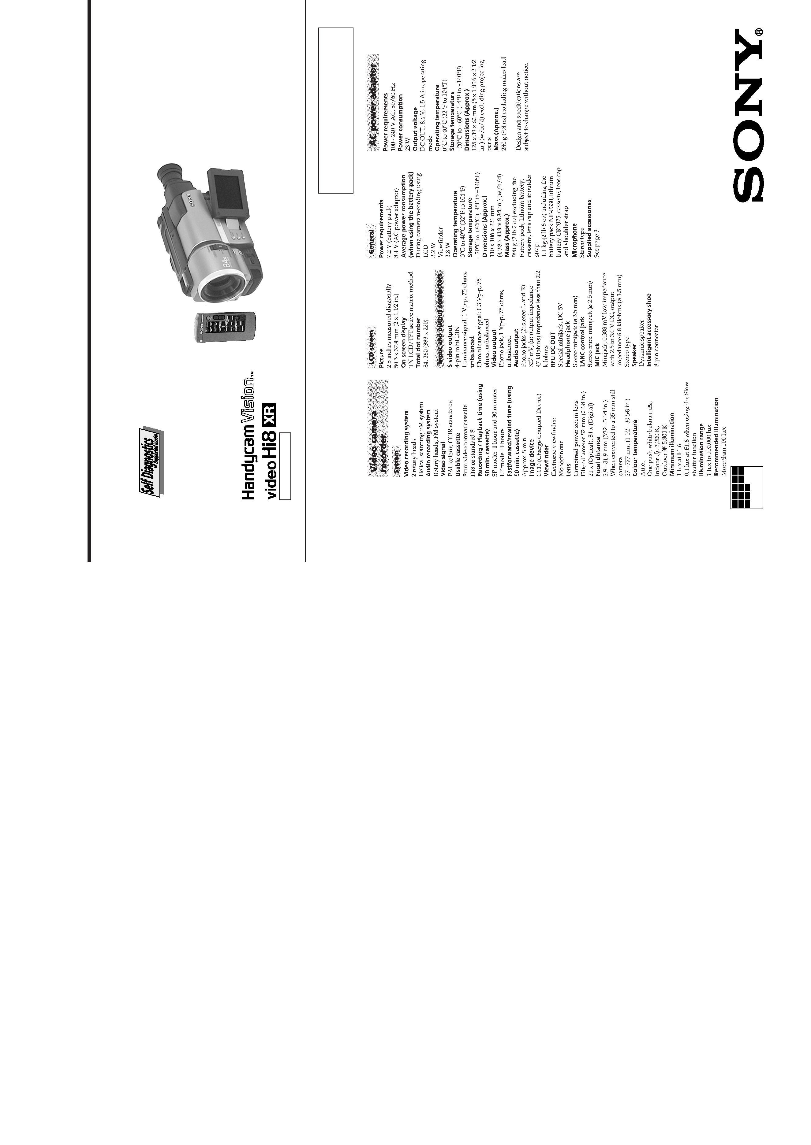
Battery terminal `
DC IN terminal
Battery SIG terminal
Battery switch
Battery terminal '
SERVICE NOTE
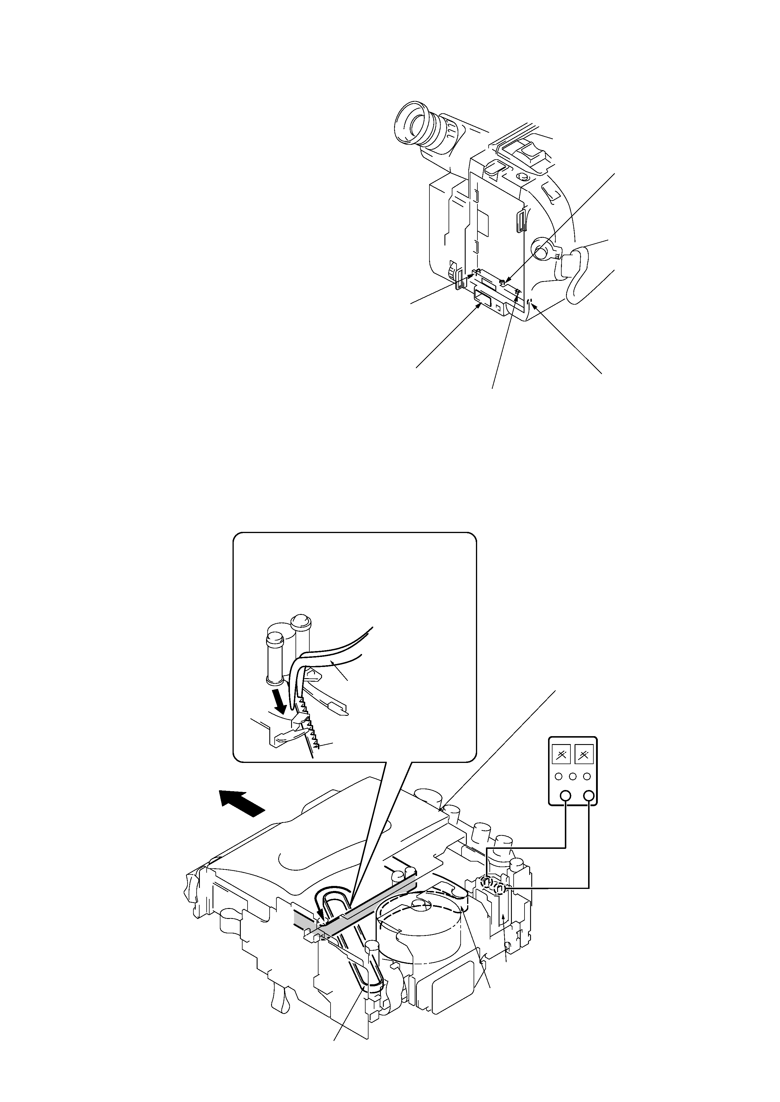
6
Pull the timing belt in the direction of arrow
A
with a pinsette while pressing the cassette lid
(take care not to damage) to adjust the
bending of a tape.
7
Let go your hold the cassette
lid and rise the cassette
compartment to take out a cassette.
A
Pinsette
Timing belt
Press the cassette lid not to rise the
cassette compartment
+
[DC power supply]
(+5V)
Loading motor
Adjust the bending of a tape
Timing belt
1 Refer to 2-1. to remove the front panel assembly.
2 Refer to 2-2. to remove the cabinet (R) assembly.
3 Refer to 2-7. to remove the battery panel assembly.
4 Refer to 2-7. to remove the cabinet (L) assembly.
5 Add +5V from the DC POWER SUPPLY and unload with a
pressing the cassette lid.
2. TO TAKE OUT A CASSETTE WHEN NOT EJECT (FORCE EJECT)
1. POWER SUPPLY DURING REPAIRS
In this unit, about 10 seconds after power is supplied (8.4V) to the
battery terminal using the service power cord (J-6082-223-A), the
power is shut off so that the unit cannot operate.
This following three methods are available to prevent this. Take
note of which to use during repairs.
Method 1.
Connect the servicing remote commander RM-95 (J-6082-053-B)
to the LANC jack, and set the remote commander switch to the
"ADJ" side.
Method 2.
Press the battery switch of the battery terminal using adhesive tape,
etc.
Method 3.
Use the DC IN terminal. (Use the AC power adaptor.)
5
Note: The self-diagnosis display data will be backed up by the coin-type lithium battery. When this coin-type lithium battery is
disconnected, the self-diagnosis data will be lost by initialization.
1. Self-diagnosis Function
When problems occur while the unit is operating, the self-diagnosis
function starts working, and displays on the viewfinder or Display
window what to do. This function consists of two display; self-
diagnosis display and service mode display.
Details of the self-diagnosis functions are provided in the Instruction
manual.
SELF-DIAGNOSIS FUNCTION
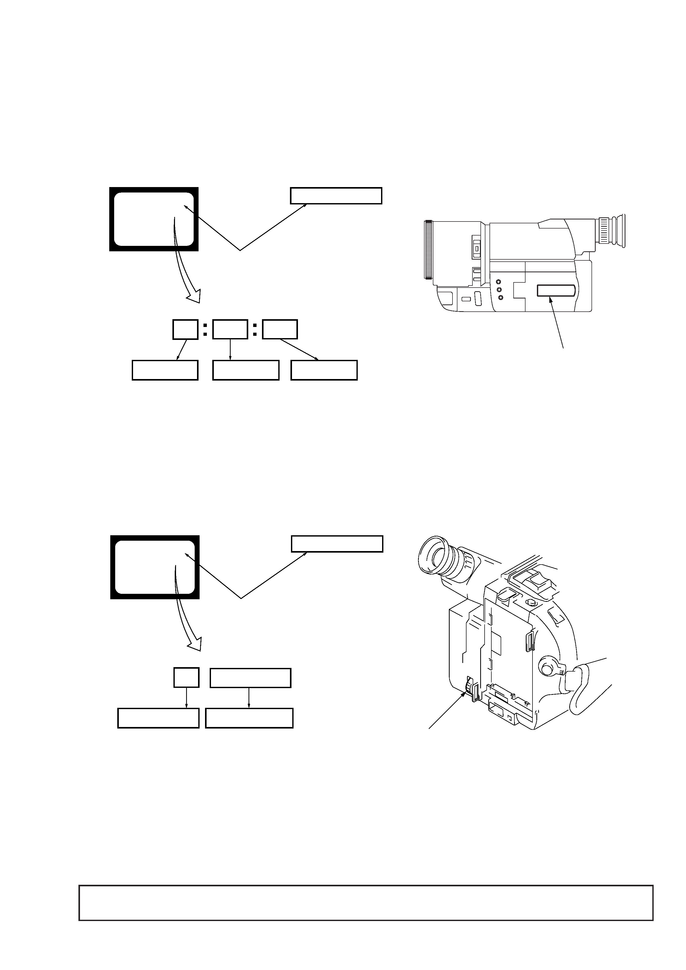
2. Self-diagnosis display
When problems occur while the unit is operating, the counter of the
viewfinder or Display window shows a 4-digit display consisting
of an alphabet and numbers, which blinks at 3.2 Hz. This 5-character
display indicates the "repaired by:", "block" in which the problem
occurred, and "detailed code" of the problem.
3. Service Mode Display
The service mode display shows up to six self-diagnosis codes shown in the past.
3-1. Display Method
While pressing the "STOP" key, set the switch from OFF to "PLAYER", and continue pressing the "STOP" key for 5 seconds continuously.
The service mode will be displayed, and the counter will show the backup No. and the 5-character self-diagnosis codes.
3-2. Switching of Backup No.
By rotating the control dial, past self-diagnosis codes will be shown in order. The backup No. in the [] indicates the order in which the
problem occurred. (If the number of problems which occurred is less than 6, only the number of problems which occurred will be shown.)
[1] : Occurred first time
[4] : Occurred fourth time
[2] : Occurred second time
[5] : Occurred fifth time
[3] : Occurred third time
[6] : Occurred the last time
3-3. End of Display
Turning OFF the power supply will end the service mode display.
Viewfinder
Display window
Blinks at 3.2 Hz
Refer to page 6
Self-diagnosis Code table
C : Corrected by customer
H : Corrected by dealer
E : Corrected by service engineer
Repairede by :
Block
Detailed Code
Indicates the appropriate step to be taken
E. g.
31 ... Reload the tape.
32 ... Turn on power again.
C
3 1
1 1
C : 3 1 : 1 1
C : 3 1 : 1 1
Viewfinder
Display window
Lights up
Order of previous errors
Backup No.
Self-diagnosis codes
[3]
C : 3 1 : 1 1
3 C : 3 1 : 1 1
[3] C : 3 1 : 1 1
Display window
Control dial