CCD-TRV101/TRV101E
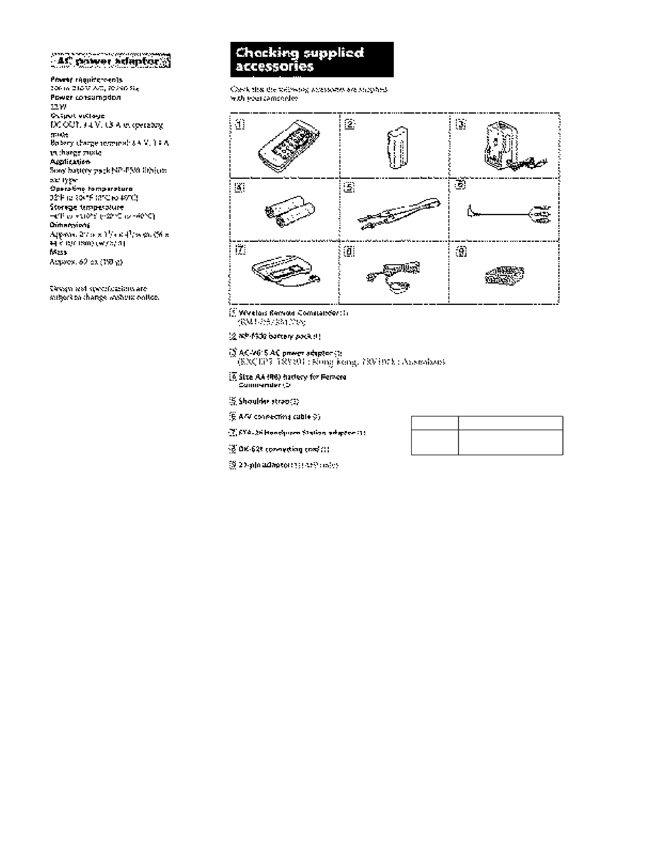
RMT-715/RMT-716
US Model
Canadian Model
CCD-TRV101
AEP Model
Australian Model
CCD-TRV101E
E Model
Hong Kong Model
CCD-TRV101/TRV101E
SERVICE MANUAL
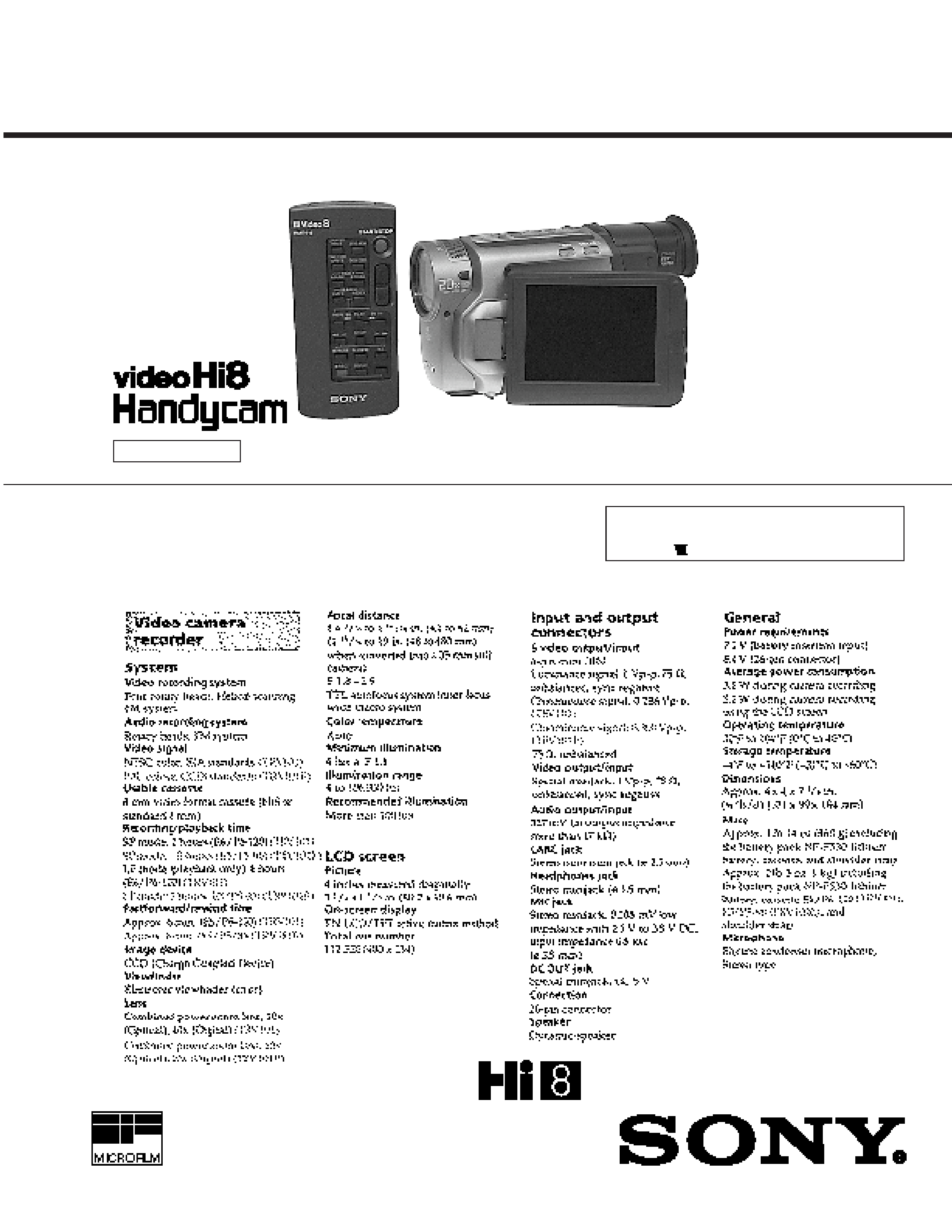
VIDEO CAMERA RECORDER
T2 MECHANISM
Photo : CCD-TRV101
SPECIFICATIONS
For MECHANISM ADJUSTMENT, refer to the
"8mm Video MECHANICAL ADJUSTMENT
MANUAL
" (9-973-886-11).
-- Continued on next page --
NTSC : CCD-TRV101
PAL :
CCD-TRV101E
-- 2 --
SAFETY-RELATED COMPONENT WARNING!!
COMPONENTS IDENTIFIED BY MARK
! OR DOTTED LINE
WITH MARK
! ON THE SCHEMATIC DIAGRAMS AND IN THE
PARTS LIST ARE CRITICAL TO SAFE OPERATION. REPLACE
THESE COMPONENTS WITH SONY PARTS WHOSE PART
NUMBERS APPEAR AS SHOWN IN THIS MANUAL OR IN
SUPPLEMENTS PUB-LISHED BY SONY.
1.
Check the area of your repair for unsoldered or poorly-
soldered connections. Check the entire board surface for
solder splashes and bridges.
2.
Check the interboard wiring to ensure that no wires are
"pinched" or contact high-wattage resistors.
3.
Look for unauthorized replacement parts, par-ticularly
transistors, that were installed during a previous repair. Point
them out to the customer and recommend their replacement.
4.
Look for parts which, through functioning, show obvious
signs of deterioration. Point them out to the customer and
recommend their replace-ment.
5.
Check the B+ voltage to see it is at the values specified.
6.
Flexible Circuit Board Repairing
· Keep the temperature of the soldering iron around 270°C
during repairing.
· Do not touch the soldering iron on the same conductor of
the circuit board (within 3 times).
· Be careful not to apply force on the conductor when
soldering or unsoldering.
SAFETY CHECK-OUT
After correcting the original service problem, perform the following
safety checks before releasing the set to the customer.
ATTENTION AU COMPOSANT AYANT RAPPORT
À LA SÉCURITÉ!
LES COMPOSANTS IDENTIFÉS PAR UNE MARQUE
! SUR
LES DIAGRAMMES SCHÉMATIQUES ET LA LISTE DES
PIÈCES SONT CRITIQUES POUR LA SÉCURITÉ DE
FONCTIONNEMENT. NE REMPLACER CES COMPOSANTS
QUE PAR DES PIÈSES SONY DONT LES NUMÉROS SONT
DONNÉS DANS CE MANUEL OU DANS LES SUPPÉMENTS
PUBLIÉS PAR SONY.
RMT-716 TRV101E : AEP model
RMT-715 EXCEPT
TRV101E : AEP model

-- 3 --
TABLE OF CONTENTS
SERVICE NOTE ·································································· 6
1.
GENERAL
Getting started
Charging and installing the battery pack ······························· 1-1
Inserting a cassette ································································· 1-3
Basic operations
Camera recording ··································································· 1-4
Hints for better shooting ························································ 1-7
Checking the recorded picture ··············································· 1-9
Playing back a tape ································································ 1-9
Searching for the end of the picture ······································· 1-12
Advanced operations
Using alternative power sources ············································ 1-12
Changing the mode settings ··················································· 1-14
Letting the subject monitor the shot ······································ 1-16
Recording with the date or time ············································· 1-17
Fade-in and fade-out ······························································ 1-18
Enjoying picture effect ··························································· 1-19
Using the wide mode function ··············································· 1-20
Shooting scenery in several short takes ································· 1-21
Superimposing a title ····························································· 1-21
Making your own original title ·············································· 1-23
Releasing the STEADYSHOT function ································ 1-24
Using the PROGRAM AE function ······································· 1-25
Focusing manually ································································· 1-26
Adjusting the exposure ·························································· 1-27
Shooting with backlighting ···················································· 1-28
Re-recording a picture in the middle of a recorded tape ······· 1-28
Optimizing the tape condition before recording ···················· 1-29
Watching on a TV screen ······················································· 1-30
Searching the boundaries of recorded tape ···························· 1-31
Returning to a preregistered position ····································· 1-32
Locating the marking position ··············································· 1-33
Writing the RC time code on a recorded tape ························ 1-36
Editing onto another tape ······················································· 1-37
Recording from a VCR or TV ··············································· 1-38
Additional information
Changing the vanadium-lithium battery in the camcorder ···· 1-39
Resetting the date and time ···················································· 1-40
Usable cassettes and playback modes ···································· 1-41
Tips for using the battery pack ·············································· 1-41
Maintenance information and precautions ····························· 1-43
Using your camcorder abroad ················································ 1-45
Trouble check ········································································ 1-46
Identifying the parts ······························································· 1-49
Warning indicators ································································· 1-54
2.
DISASSEMBLY
·
PRECAUTIONS ON REPAIR ········································ 2-1
2-1.
REMOVAL OF FRONT PANEL ASSEMBLY ··············· 2-1
2-2.
REMOVAL OF CABINET (R) ASSEMBLY ················ 2-2
2-3.
REMOVAL OF PD-68 BOARD AND
LCD902 (LCD MODULE) ············································· 2-3
2-4.
REMOVAL OF SPEAKER AND
CONTROL SWITCH BLOCK (FK-7000) ····················· 2-3
2-5.
REMOVAL OF BACK PANEL ASSEMBLY ················· 2-4
2-6.
REMOVAL OF CONTROL SWITCH BLOCK (CF) ····· 2-4
2-7.
REMOVAL OF MC-110 BOARD AND
VC-175 BOARD ····························································· 2-5
2-8.
REMOVAL OF MA-261 BOARD AND
MICROPHONE UNIT ···················································· 2-5
2-9.
REMOVAL OF IC790 (CCD IMAGER) ························ 2-6
2-10. REMOVAL OF LENS FRAME AND
FP-365 FLEXIBLE ························································· 2-6
2-11. REMOVAL OF MECHANISM ······································ 2-7
2-12. REMOVAL OF CENTER FRAME ASSEMBLY ··········· 2-7
2-13. REMOVAL OF EVF (REAR) CABINET AND
VF-97 BOARD ································································ 2-8
2-14. REMOVAL OF EVF BLOCK ········································· 2-9
2-15. REMOVAL OF CABINET (L) ······································· 2-9
2-16. REMOVAL OF CONTROL SWITCH BLOCK (PS) ····· 2-10
2-17. REMOVAL OF GRIP LOCK ASSEMBLY AND
CONTROL SWITCH BLOCK (ZOOM) ························ 2-10
2-18. REMOVAL OF LI-54 BOARD ······································· 2-11
2-19. REMOVAL OF JK-147 BOARD ···································· 2-11
2-20. VC-175 BOARD SERVICE POSITION
(FOR CHECK AND ADJUSTMENT) ···························· 2-12
2-21. INTERNAL VIEWS ························································ 2-13
2-22. CIRCUIT BOARDS LOCATION ··································· 2-14
3.
BLOCK DIAGRAMS
3-1.
OVERALL BLOCK DIAGRAM ···································· 3-1
3-2.
CAMERA BLOCK DIAGRAM ····································· 3-4
3-3.
VIDEO BLOCK DIAGRAM ·········································· 3-7
3-4.
SERVO BLOCK DIAGRAM ·········································· 3-10
3-5.
VTR/CAMERA CONTROL BLOCK DIAGRAM ········· 3-13
3-6.
AUDIO BLOCK DIAGRAM ·········································· 3-16
3-7.
MODE CONTROL BLOCK DIAGRAM ······················· 3-19
3-8.
EVF BLOCK DIAGRAM ··············································· 3-21
3-9.
LCD BLOCK DIAGRAM ·············································· 3-23
3-10. POWER BLOCK DIAGRAM ········································· 3-26
4.
PRINTED WIRING BOARDS AND
SCHEMATIC DIAGRAMS
4-1.
FRAME SCHEMATIC DIAGRAM ································ 4-1
4-2.
PRINTED WIRING BOARDS AND
SCHEMATIC DIAGRAMS ············································ 4-5
· VC-175 (MAIN) PRINTED WIRING BOARD ··········· 4-6
· VC-175 (CAMERA 1), FP-454 (CCD-IMAGER)
SCHEMATIC DIAGRAMS ···························· 4-14
· VC-175 (CAMERA 2) SCHEMATIC DIAGRAM ······ 4-17
· VC-175 (CAMERA 3),
FP-365 (STEADY SHOT SENSOR)
PRINTED WIRING BOARD AND
SCHEMATIC DIAGRAMS ···························· 4-21
· VC-175 (CAMERA 4) SCHEMATIC DIAGRAM ······ 4-25
· VC-175 (VIDEO 1) SCHEMATIC DIAGRAM ··········· 4-29
· VC-175 (VIDEO 2) SCHEMATIC DIAGRAM ··········· 4-33
· MC-110 (MULTI CONNECTOR)
PRINTED WIRING BOARD ························· 4-36
· VC-175 (I/O), MC-110 (MULTI CONNECTOR)
SCHEMATIC DIAGRAM ······························ 4-37
· VC-175 (MODE CONTROL)
SCHEMATIC DIAGRAM ······························ 4-41
· VC-175 (CAMERA/VTR CONTROL)
SCHEMATIC DIAGRAM ······························ 4-45
· VC-175 (MACHANISM CONTROL),
FP-316 (MECHANISM SENSOR)
PRINTED WIRING BOARDS AND
SCHEMATIC DIAGRAMS ···························· 4-49
· VC-175 (AUDIO AMP) SCHEMATIC DIAGRAM ···· 4-52
· VC-175 (POWER) SCHEMATIC DIAGRAM ············· 4-55
· LI-54 (BATTERY TERMINAL),
JK-147 (INPUT/OUTPUT TERMINAL)
PRINTED WIRING BOARD ························· 4-60

-- 4 --
· LI-54 (BATTERY TERMINAL),
JK-147 (INPUT/OUTPUT TERMINAL)
SCHEMATIC DIAGRAMS ···························· 4-63
· MA-261 (AUDIO MIC AMP)
PRINTED WIRING BOARD ························· 4-67
· MA-261 (AUDIO MIC AMP)
SCHEMATIC DIAGRAM ······························ 4-69
· VF-97 (EVF) SCHEMATIC DIAGRAM ····················· 4-73
· VF-97 (EVF) PRINTED WIRING BOARD ················ 4-77
· PD-68 (LCD) PRINTED WIRING BOARD ················ 4-84
· PD-68 (LCD) SCHEMATIC DIAGRAM ····················· 4-87
5.
REPAIR PARTS LIST
5-1.
EXPLODED VIEWS ······················································ 5-1
5-1-1. OVERALL SECTION ····················································· 5-1
5-1-2. CABINET (R) ASSEMBLY, LCD BLOCK ···················· 5-2
5-1-3. EVF BLOCK ··································································· 5-3
5-1-4. MAIN BLOCK ································································ 5-4
5-1-5. CENTER FRAME BLOCK ············································ 5-5
5-1-6. CABINET BLOCK-1 ······················································ 5-6
5-1-7. CABINET BLOCK-2 ······················································ 5-7
5-1-8. ZOOM LENS BLOCK (VCL-4210VB) ························· 5-8
5-1-9. LENS BLOCK ································································ 5-9
5-1-10. CASSETTE COMPARTMENT BLOCK ····················· 5-10
5-1-11. LS CHASSIS BLOCK ·················································· 5-11
5-1-12. MECHANISM CHASSIS BLOCK-1 ··························· 5-12
5-1-13. MECHANISM CHASSIS BLOCK-2 ··························· 5-13
5-2.
ELECTRICAL PARTS LIST ·········································· 5-14
6.
ADJUSTMENTS
6-1.
CAMERA SECTION ADJUSTMENT ··························· 6-1
1-1.
PREPARATIONS BEFORE ADJUSTMENT ················· 6-1
1-1-1. List of service tools ························································· 6-1
1-1-2. Precautions ······································································ 6-2
1.
Switch settings ································································· 6-2
2.
Adjustment sequence ······················································· 6-2
3.
Subject ············································································· 6-2
1-1-3. Preparations ····································································· 6-3
1-1-4. Adjustment remote commander (RM-95 upgraded) ······· 6-4
1.
Using the adjustment remote commander ······················· 6-4
2.
Precautions when using
the adjustment remote commander ·································· 6-5
1-1-5. Page F address list ··························································· 6-6
1-1-6. Page E address list ··························································· 6-9
1-2.
CAMERA SYSTEM ADJUSTMENTS ·························· 6-10
1-2-1. Adjustment points when major parts
have been replaced ·························································· 6-10
1-2-2. Preparation for adjustment ·············································· 6-10
1-2-3. Initialization of Pages E and F data ································· 6-11
1-2-4. Modification of Page F data ············································ 6-12
1-2-5. Modification of Page E data ············································ 6-12
1-2-6. Reference : Conversion between
the hexadecimal number and decimal number. ··············· 6-13
1-2-7. 28MHz crystal oscillator adjustment ······························· 6-13
1-2-8. HALL adjustment ···························································· 6-14
1-2-9. Flange back adjustment ··················································· 6-16
1-2-10. Flange back check ························································· 6-17
1-2-11. Picture frame setting ····················································· 6-18
1-2-12. Color reproduction adjustment ····································· 6-19
1-2-13. IRIS IN/OUT adjustment ·············································· 6-20
1-2-14. MAX GAIN adjustment ················································ 6-21
1-2-15. Auto white balance reference data input ······················· 6-22
1-2-16. Auto white balance adjustment ····································· 6-23
1-2-17. White balance check ····················································· 6-24
1-2-18. Velocity sensor sensitivity adjustment ·························· 6-25
1-3.
COLOR ELECTRONIC VIEWFINDER SYSTEM
ADJUSTMENTS ····························································· 6-26
1-3-1. EVR initial data input ······················································ 6-28
1-3-2. VCO adjustment (VC-175 board) ··································· 6-28
1-3-3. BRIGHT adjustment (VC-175 board) ····························· 6-29
1-3-4. CONTRAST adjustment (VC-175 board) ······················· 6-29
1-3-5. Back light adjustment (VC-175 board) ··························· 6-30
1-3-6. White balance adjustment ··············································· 6-30
1-3-7. AUTO ON level adjustment ············································ 6-31
1-4.
LCD SYSTEM ADJUSTMENTS ··································· 6-32
1-4-1. LCD system adjustment (PD-68 board) ·························· 6-32
1-4-2. EVR initial data input ······················································ 6-32
1-4-3. VCO adjustment (PD-68 board) ······································ 6-33
1-4-4. Horizontal display position adjustment (PD-68 board) ··· 6-34
1-4-5. D range adjustment (PD-68 board) ································· 6-35
1-4-6. BRIGHT adjustment (PD-68 board) ······························· 6-35
1-4-7. CONTRAST adjustment (PD-68 board) ························· 6-36
1-4-8. V-COM level adjustment (PD-68 board) ························· 6-36
1-4-9. Color adjustment for NTSC model (PD-68 board) ········· 6-37
1-4-10. Hue adjustment for NTSC model (PD-68 board) ········· 6-37
1-4-11. Burst cleaning adjustment for PAL model
(PD-68 board) ······························································· 6-38
1-4-12. Color adjustment for PAL model (PD-68 board) ·········· 6-38
1-4-13. V COM adjustment ······················································· 6-39
1-4-14. White balance adjustment (PD-68 board) ····················· 6-40
1-5.
ARRANGEMENT DIAGRAM FOR
ADJUSTMENT PARTS ·················································· 6-42
6-2.
MECHANICAL SECTION ADJUSTMENTS ··············· 6-45
2-1.
OPERATING WITHOUT A CASSETTE ······················· 6-45
2-2.
TAPE PATH ADJUSTMENT ·········································· 6-45
1.
Preparations for adjustments ··········································· 6-45
6-3.
VIDEO SECTION ADJUSTMENT ································ 6-46
3-1.
PREPARATIONS BEFORE ADJUSTMENT ················· 6-46
3-1-1. Equipments to be used ····················································· 6-46
3-1-2. Precaution In adjustment ················································· 6-47
3-1-3. Connector for adjustments ··············································· 6-47
3-1-4. Connecting the equipments ············································· 6-48
3-1-5. Checking the input signal ················································ 6-49
1.
S VIDEO input ································································ 6-49
2.
VIDEO input ··································································· 6-50
3-1-6. Alignment tape ································································ 6-50
3-1-7. Input/Output level and impedance ··································· 6-51
3-1-8. Recording mode (Normal/Hi8) switching ······················· 6-51
3-1-9. Page D address list ·························································· 6-52
3-1-10. Page F address list (See Page 6-6) ································ 6-52
3-1-11. Page E address list (See Page 6-9) ································ 6-52
3-2.
SYSTEM CONTROL ADJUSTMENT ·························· 6-53
3-2-1. Initialization of pages E and F data (See page 6-11) ······· 6-53
3-2-2. Modification of Page F data (See page 6-12) ·················· 6-53
3-2-3. Modification of Page E data (See page 6-12) ·················· 6-53
3-2-4. Initialization of Page D ···················································· 6-53
3-2-5. Modification of page D data ············································ 6-53
3-2-6. Battery down adjustment (VC-175 board) ······················ 6-54
3-2-7. Capstan FG offset adjustment (VC-175 board) ··············· 6-55
3-2-8. Switching position adjustment ········································ 6-56
3-4.
VIDEO SYSTEM ADJUSTMENT ································· 6-56
3-4-1. 28MHz crystal oscillator adjustment (See page 6-13) ···· 6-56
3-4-2. AFC fo adjustment (VC-175 board) ································ 6-56
3-4-3. Filter fo adjustment (VC-175 board) ······························· 6-57
3-4-4. Y OUT adjustment (VC-175 board) ································ 6-58

-- 5 --
* The color reproduction frame is shown after the page of
ARRANGEMENT DIAGRAM FOR ADJUSTMENT PARTS.
3-4-5. C OUT adjustment (VC-175 board) ································ 6-58
3-4-6. RP filter fo adjustment (VC-175 board) ·························· 6-59
3-4-7. REC Y current adjustment (VC-175 board) ···················· 6-60
3-4-8. REC C current adjustment (VC-175 board) ···················· 6-61
6-5.
AUDIO SYSTEM ADJUSTMENT ································· 6-62
3-5-1. 1.5MHz deviation adjustment ········································· 6-63
3-5-2. 1.7MHz deviation adjustment ········································· 6-64
3-5-3. BPF adjustment ······························································· 6-65
3-6.
ARRANGEMENT DIAGRAM FOR
ADJUSTMENT PARTS ·················································· 6-66
3-7.
SERVICE MODE ···························································· 6-69
1.
Setting the TEST mode and VTR & CAM mode ON ····· 6-69
2.
Emergency memory address ············································ 6-70
3.
EMG code (Emergency code) ········································· 6-71
4.
MSW code ······································································· 6-71
5.
Input/output selection check ············································ 6-72
6.
Condensation and head clogging checks ························· 6-72
7.
VTR state check (1) ························································· 6-73
8.
VTR state check (2) ························································· 6-73
9.
VTR state check (3) ························································· 6-73
10.
Key input check ······························································· 6-74
11.
Key input check (A/D port) ············································· 6-74
12.
Use history check ···························································· 6-75