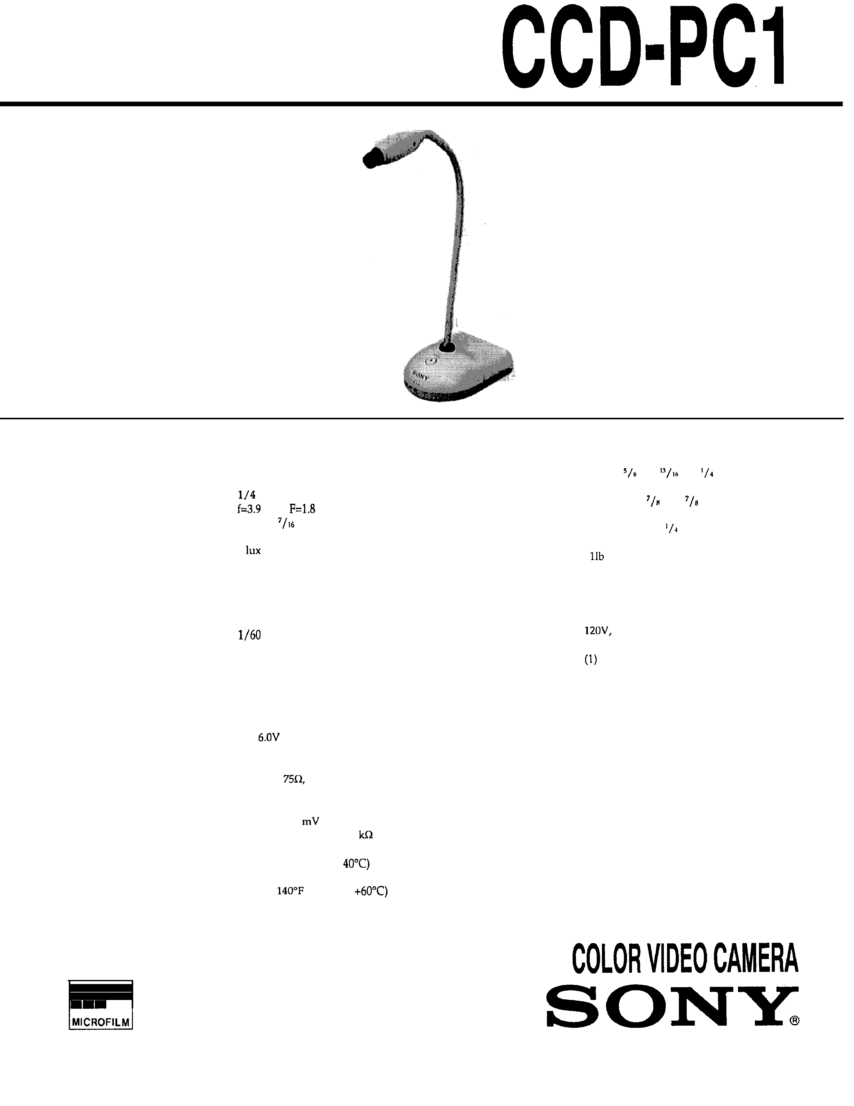
SERVICE MANUAL
US Model
SPECIFICATIONS
System
Video
signal
NTSC color, EIA standards
Image
device
inch color CCD (270,000 pixels)
Lens
mm,
Macro
Approx.
in (10 mm)
Minimum
illumination
9
Illumination
range
9 to 10,000 lux
White
balance
Auto
Iris
Manual
Electronic
shutter
fixed
Focus
adjustment
Manual
Dimensions (w x h x d)
Base: approx. 3
x 1
x 5
in (91 x 45 x 132 mm)
Camera: approx. 1 x
x 2
in
(25 x 22 x 73 mm)
Arm length: approx. 11
in (285
mm)
Mass
Approx.
7 oz (650 g)
Microphone
Monaural
DC jack
6.0 V
Supplied accessories
AC power adaptor (AC
60 Hz) (1)
Audio/video
cable
(1)
Operating
instructions
Design and specifications are subject to change
General
Power
requirements
DC
without
notice.
Power
consumption
1.8 w
Video
output
1 Vp-p,
unbalanced, sync
negative
S video output 4-pin mini DIN
Audio
output
Output
327
(monaural),
impedance less than 2.2
Operating
temperature
41°F to 104°F (5°C to
Storage
temperature
-4°F to
(-20°C to
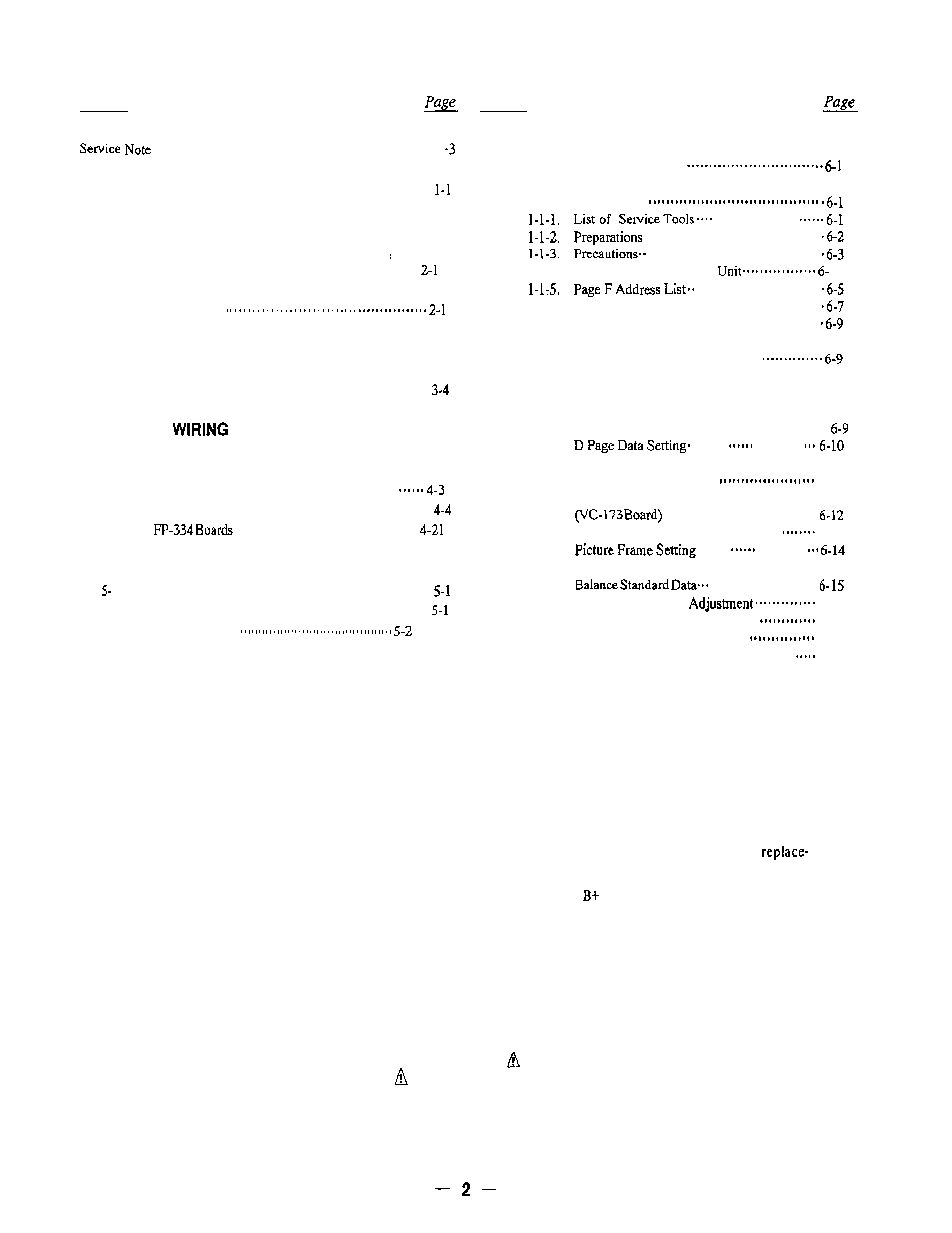
TABLE OF CONTENTS
Section
Title
Section
Title
. . . . . . . . . . . . . . . . . . . . . . . . . . . . . . . . . . . . . . . . . . . . . . . . . . . . . . . . . . . . . . .
6.
ADJUSTMENTS
1.
2.
3.
4.
5.
GENERAL . . . . . . . . . . . . . . . . . . . . . . . . . . . . . . . . . . . . . . . . . . . . . . . . . . . . . . . .
DISASSEMBLY
2-1. Removal of Head Cabinet (Upper, Lower) and
CD-144 Board . . . . . . . . . . . . . . . . . . . . . . . . . . . . . . . . ..*...... . . . . . . .
2-2. Removal of Optical Filter Block and
CCD Block Assy
DIAGRAMS
3-1. Overall Block Diagram . . . . . . . . . . . . . . . . . . . . . . . . . . . . . . . . . . ...3-1
3-2. Camera Block Diagram . . . . . . . . . . . . . . . . . . . . . . . . . . . . . . . . . . . . .
PRINTED
BOARDS AND SCHEMATIC
DIAGRAMS
4-l. Frame Schematic Diagram . . . . . . . . . . . . . . . . . . . . . . . . . . . . . . ...4-1
4-2. Printed Wiring Boards and Schematic Diagrams
l
VC- 173 Board . . . . . . . . . . . . . . . . . . . . . . . . . . . . . . . . . . . . . . . . . . . . . . . . .
. CD-144,
. . . . . . . . . . . . . . . . . . . . . . . . . . . . . . . . . . .
REPAIR PARTS LIST
1. Exploded View . . . . . . . . . . . . . . . . . . . . . . . . . . . . . . . . . . . . . . . . . . . . . . .
S-l-l. Head Cabinet Section . . . . . . . . . . . . . . . . . . . . . . . . . . . . . . . . . .
5-2. Electrical Parts List
6-l. Camera Section Adjustment
l-l. Preparations Before Adjustment
(Camera Section)
...................
........................................
.......................................
l-l-4.
Adjusting Remote Control
4
............................
l-l-6. Data Processing ...................................
1-2. Camera Syetem Adjustment ..........................
1-2-1.
l-2-2.
l-2-3.
l-2-4.
1-2-s.
l-2-6.
l-2-7.
l-2-8.
l-2-9.
Cautions
when
making
adjustments
after changing major components
Power Supply Voltage Check
(VC-173 Board) . . . . . . . . . . . . . . ..a................... 6-9
Oscillation Frequency Check
(VC-173 board) . . . . . . . . . . . . . . . . . . . . . . . . . . . . . . . . . . . .
. . . . . . . .
. . . . . . . . . . .
Adjustments Setup . . . . . . . . . . . . . . . . . . . . . . . . . . . . . . 6-10
Page F Data Initialization
6-l 1
28
MHz
Original
Oscillation
Adjustment
. . . . . . . . . . . . . , . . . . . . . . . . . . . . . . . . . .
V SUB Adjustment (VC-173 Board)
6-13
. . . . . . .
. . . . . . . . . . .
l-2-10. Entering Reference Data for the Auto White
. . . . . . . . . . . . . . . . . . . . . . .
l-2-11. Color Reproduction
6-16
1-2-12. Auto White Balance Adjustment
6-18
1-2-13. Check the Auto White Balance
6-19
1-3.
Arrangement Diagram for Adjustment Parts
6-20
SAFETY
CHECK-OUT
After correcting the original service problem, perform the following
safety checks before releasing the set to the customer:
1.
Check the area of your repair for unsoldered or
4.
Look for parts which, though functioning, show
poorly-soldered
connections.
Check
the
entire
obvious signs of deterioration. Point them out
board surface for solder splashes and bridges.
to the customer and recommend their
2.
Check the interboard wiring to ensure that no
ment.
wires
are
"pinched" or
contact
high-wattage
5.
Check the
voltage to see it is at the values
resistors.
specified.
3.
Look for unauthorized replacement parts, par-
ticularly transistors, that were installed during a
previous repair. Point them out to the customer
and recommend their replacement.
SAFETY-RELATED
COMPONENT
WARNING!!
COMPONENTS
IDENTIFIED
BY
MARK
OR
DOTTED
LINE
WITH
MARK
ON
THE
SCHEMATIC
DIAGRAMS
AND
IN
THE
PARTS
LIST
ARE
CRITICAL
TO
SAFE
OPERATION.
REPLACE
THESE
COMPONENTS
WITH
SONY
PARTS
WHOSE
PART
NUMBERS
APPEAR
AS
SHOWN
IN
THIS
MANUAL
OR
IN
SUPPLEMENTS
PUB-
LISHED
BY
SONY.
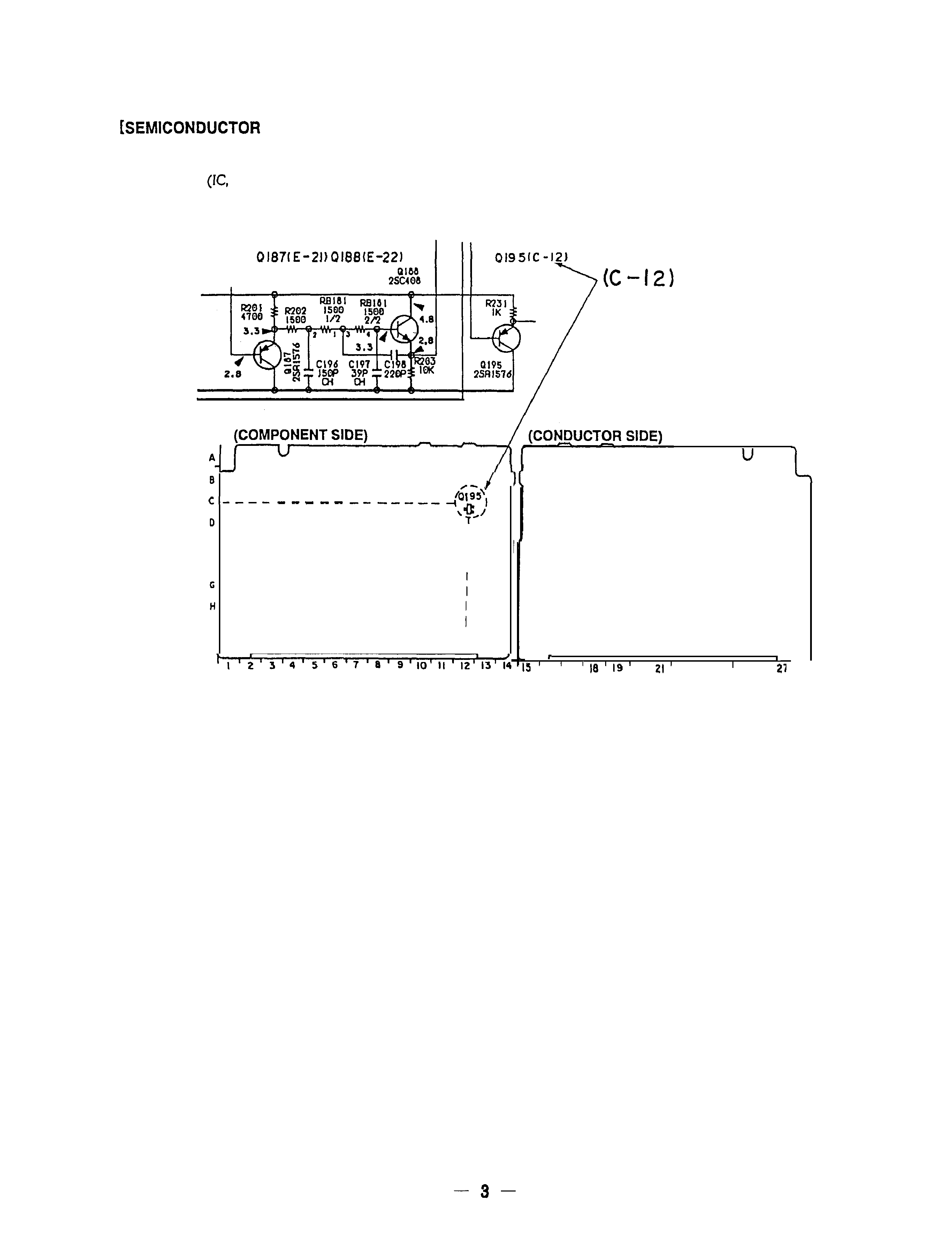
SERVICE NOTE
LOCATION
]
In this service manual,
the mounted locations of the
semiconductors
transistor, diodes) are indicated in red in
schematic diagrams. This enables to find the location on the
board easily when servicing.
1
BUFFER
LPF
BUFFER
I
.
I
E
I
F
I
I
I
J
I
,
,
I6
I7
20'
22' 23' 24
25' 26'
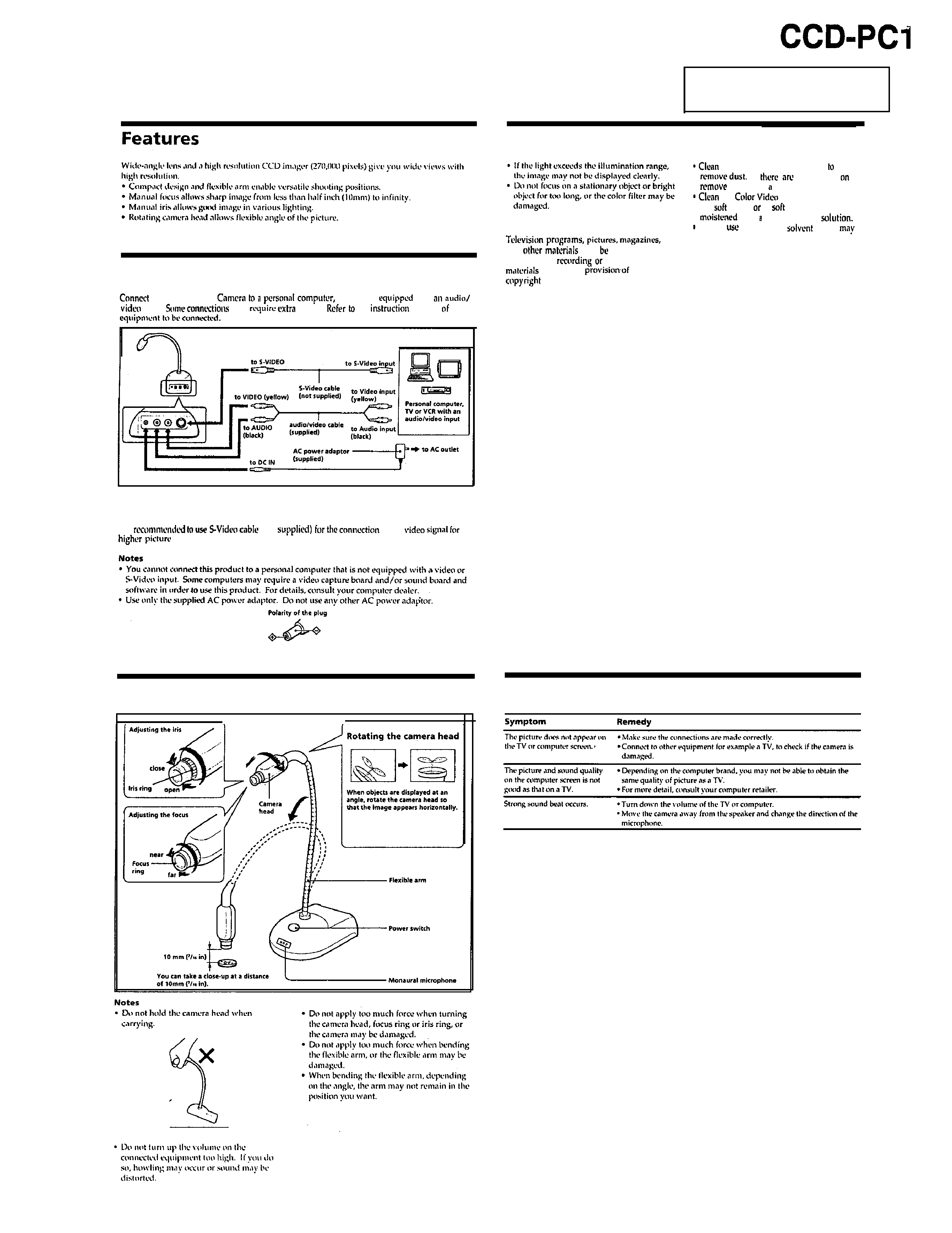
SECTION 1
GENERAL
Connections
your Color Video
TV or VCR
with
input.
may
cables.
the
manual
the
If your equipment has an S-Video input
It is
(not
of the
quality.
This section is extracted from
instruction
manual.
Precautions
Precaution on copyright
and
may
copyrighted.
Unauthorized
storing of such
violates the
the
laws.
Maintenance
the lens with a blower brush
If
fingerprints
it,
them with
soft cloth.
the
Camera body with a
dry
cloth,
a
cloth lightly
with
mild detergent
Do not
any type of
which
damage the finish.
How to use
Troubleshooting
l-l
E
CCD-PC1
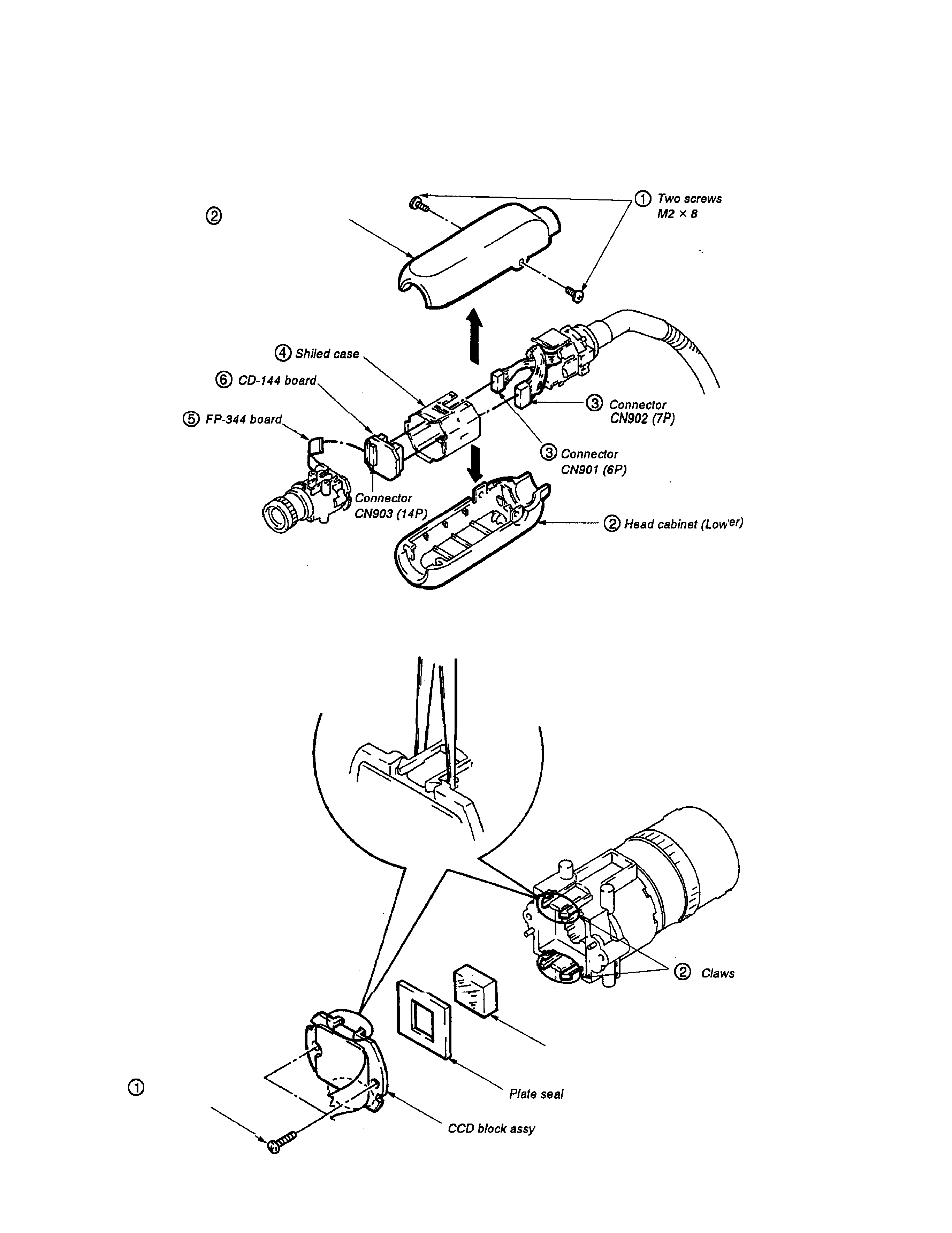
SECTION 2
DISASSEMBLY
Note
: Follow the disassembly procedure in the numerical order given.
2-1. REMOVAL OF HEAD CABINET (UPPER, LOWER) AND CD-144 BOARD
Head cabinet (Upper)
2-2. REMOVAL OF OPTICAL FILTER BLOCK AND CCD BLOCK ASSY
Note
: The optical filter block has a front and a
reverse side so take care not to confuse
them during
assembly.
Twe screws
61.7 x 6
Optical filter block
2-l E