C-357
US Model
Canadian Model
AEP Model
SERVICE MANUAL
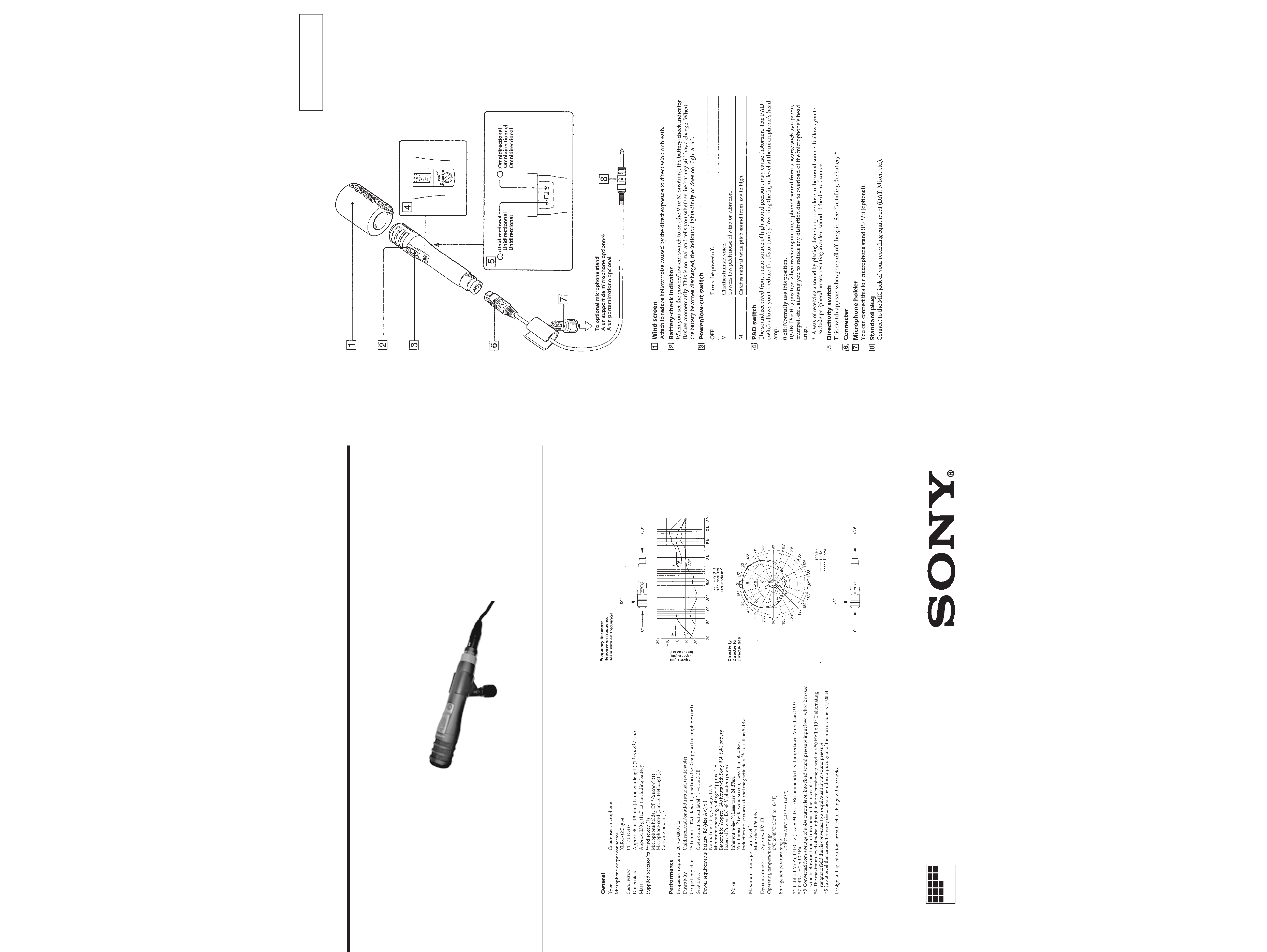
SPECIFICATIONS
SECTION 1
GENERAL
Notes on chip component replacement
· Never reuse a disconnected chip component.
· Notice that the minus side of a tantalum capacitor may be
damaged by heat.
This section is extracted from
instruction manual.
-- 2 --
CONDENSER MICROPHONE
MICROFILM
Ver 1.0 1999. 02
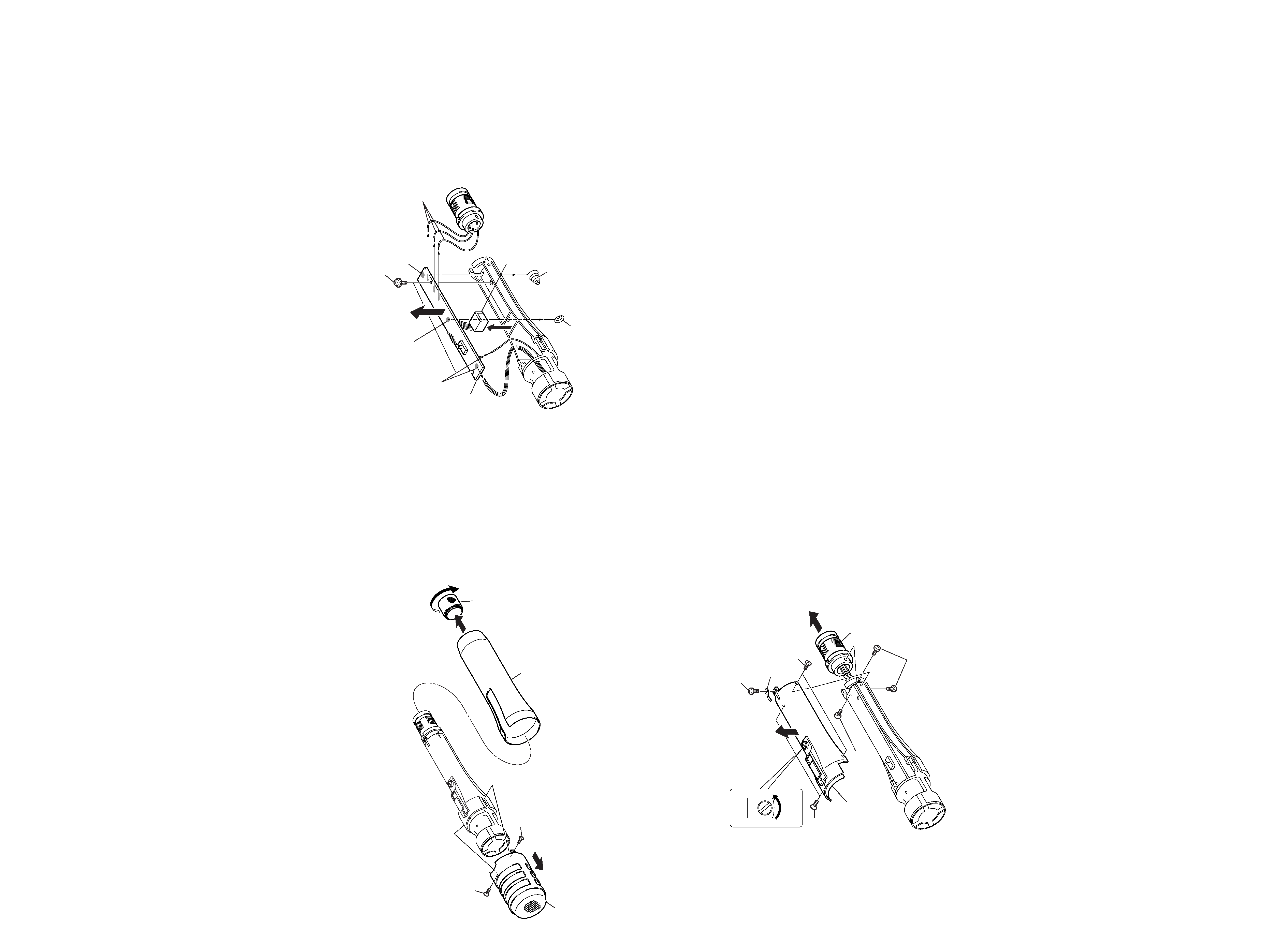
SECTION 2
DISASSEMBLY
Note :
Follow the disassembly procedure in the numerical order given.
2-1. CASE ASSY, MICROPHONE
2 Grip
3 Screw
5 Case assy, microphone
4 Screw
1 Ring, screw
Turn the Ring, screw
in the direction of the
arrow A, and remove it.
A
3 Screw (+P 2
× 6)
7 Two screws (+K 2
× 5)
6 Screw
(+K 2
× 5)
5 Chassis
4 Terminal, ground
1 Two screws
2 Two screws
8 Sleeve, connector
Note:
To re-attach it, turn the PAD knob
first in the direction of the arrow and attach it.
2-2. CHASSIS, "SLEEVE, CONNECTOR"
-- 3 --
6 Remove the two solderings
and remove the harness.
3 Remove soldering
8 AMP board
4 Terminal, plus
2 Terminal, minus
9 Transformer, output
5 Remove three solderings and
remove the three harnesses.
1 Remove soldering
7 Two screws (+PTPWH 2
× 5)
2-3. AMP BOARD
-- 4 --
C-357
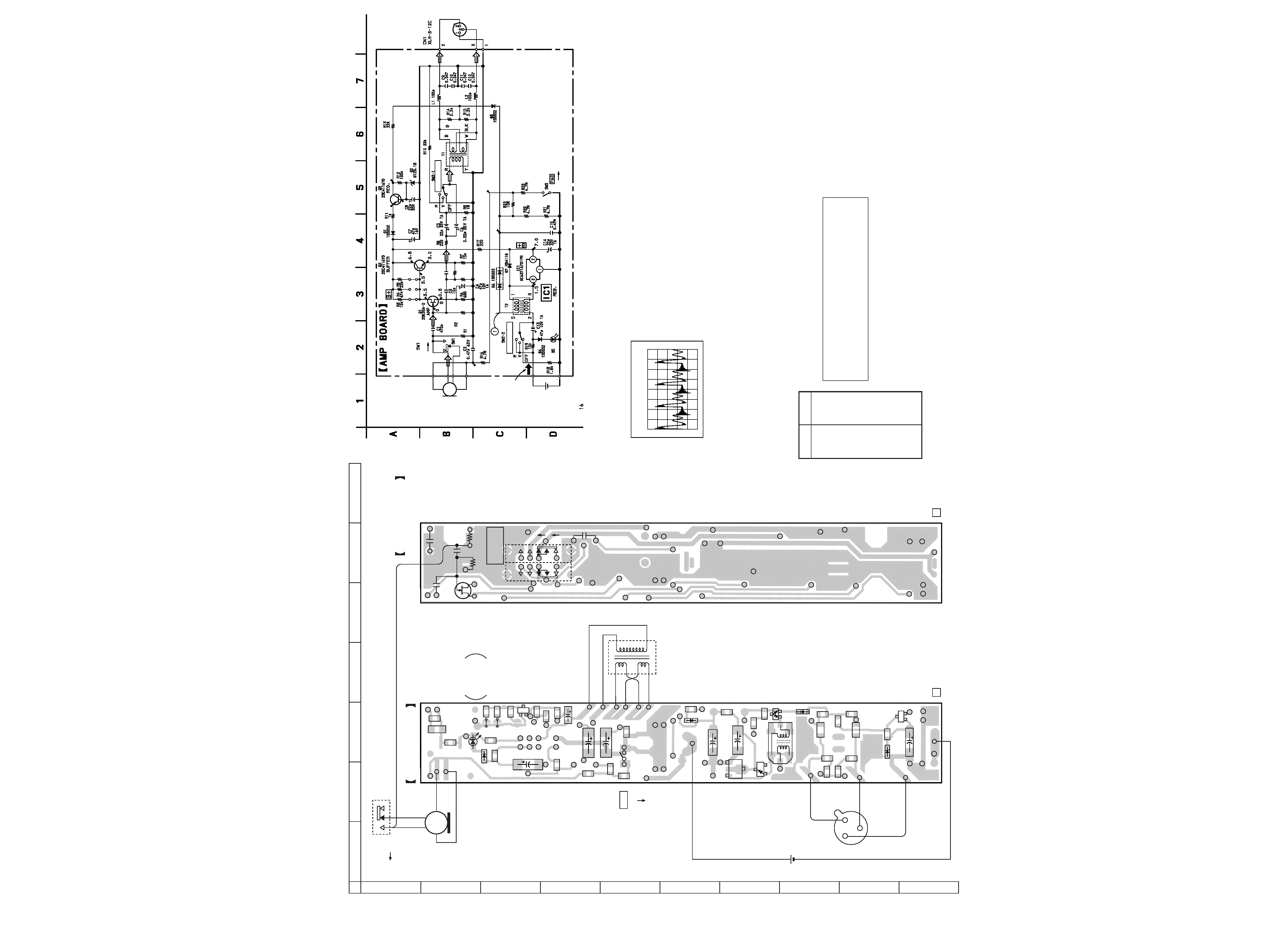
SECTION 3
DIAGRAMS
3-1. PRINTED WIRING BOARD
-- 5 --
3-2. SCHAMITIC DIAGRAM
-- 6 --
Note on Printed Wiring Board:
· X : parts extracted from the component side.
·
®
: Through hole.
· b : Pattern from the side which enables seeing.
Caution:
Pattern face side:
Parts on the pattern face side seen from
(Side B)
the pattern face are indicated.
Parts face side:
Parts on the parts face side seen from
(Side A)
the parts face are indicated.
Note on Schematic Diagram:
· All capacitors are in µF unless otherwise noted. pF: µµF
50 WV or less are not indicated except for electrolytics
and tantalums.
· All resistors are in
and 1/4 W or less unless otherwise
specified.
·
%
: indicates tolerance.
· C : panel designation.
· U : B+ Line.
· Power voltage is dc 1.5 V and fed with regulated dc power
supply from battery terminal.
· Voltages and waveforms are dc with respect to ground
under no-signal (detuned) conditions.
· Voltages are taken with a VOM (Input impedance 10 M
).
Voltage variations may be noted due to normal produc-
tion tolerances.
· Waveforms are taken with a oscilloscope.
Voltage variations may be noted due to normal produc-
tion tolerances.
· Circled numbers refer to waveforms.
· Signal path.
F
: MIC
Ref. No.
Location
D1
F-3
D2
I-3
D3
H-3
D4
B-3
D5
B-3
D6
G-3
D7
G-2
IC1
G-2
Q1
B-5
Q2
C-3
Q3
I-3
· Semiconductor
Location
1 D6 ANODE
5
µsec/div
20V/div
· Waveform
MIC1
·TOTAL CURRENT
7 mA
CAPSULE
DRY BATTERY
SIZE"AA"
(IEC DESIGNATION R6)
1PCS,1.5V
CL-220HR-C
BATTERY CHECK
INDICATOR
()
POWER/LOW-CUT
D-D CONV.
R24
100K
R25
47K
POWER/LOW-CUT
H
H
TYPE
8
(DIRECTIVITY)
UNI
OMNI
C16
0.0012
19.6
999.99M
999.99M
46.4
24.0
0
0
0
0dB
-10dB
AMP BOARD
(SIDE B)
AMP BOARD (SIDE A)
1-671-801-
12
1-671-801-
12
DRY BATTERY
SIZE"AA"
(IEC DESIGNATION R6)
1PCS,1.5V
T1
RED
RED
WHT
PUL
YEL
YEL
YEL
BRN
BRN
BLU
GRN
BLU
BLK
WHT
R3
D5
D5
D4
R5
R9
R25
R24
C16
C13
R4
C
E
B
R10
R8
R7
R19
Q2
C6
C5
C4
R18
R16
SW1
SW3
SW3
R6
R22
R23
R11
R17
D3
R14
R15
C9
C12
D1
C7
C14
IC1
D7
T2
R20
R21
D6
C10
C11
R13
L1
L2
D2
E
C
B
3
4
6
1
1
3
2
R12
Q3
C8
CN1
12
3
MIC1
CAPSULE
C3
C2
C1
C15
R1
R2
POWER
/LOW-CUT
BATTERY
CHECK
INDICATOR
Q1
M
V
OFF
SW2
1
2
S
PAD
(DIRECTIVITY)
OMNI
UNI
2
5
0dB
-10dB
12
A
B
C
D
E
F
G
H
I
J
34567
16
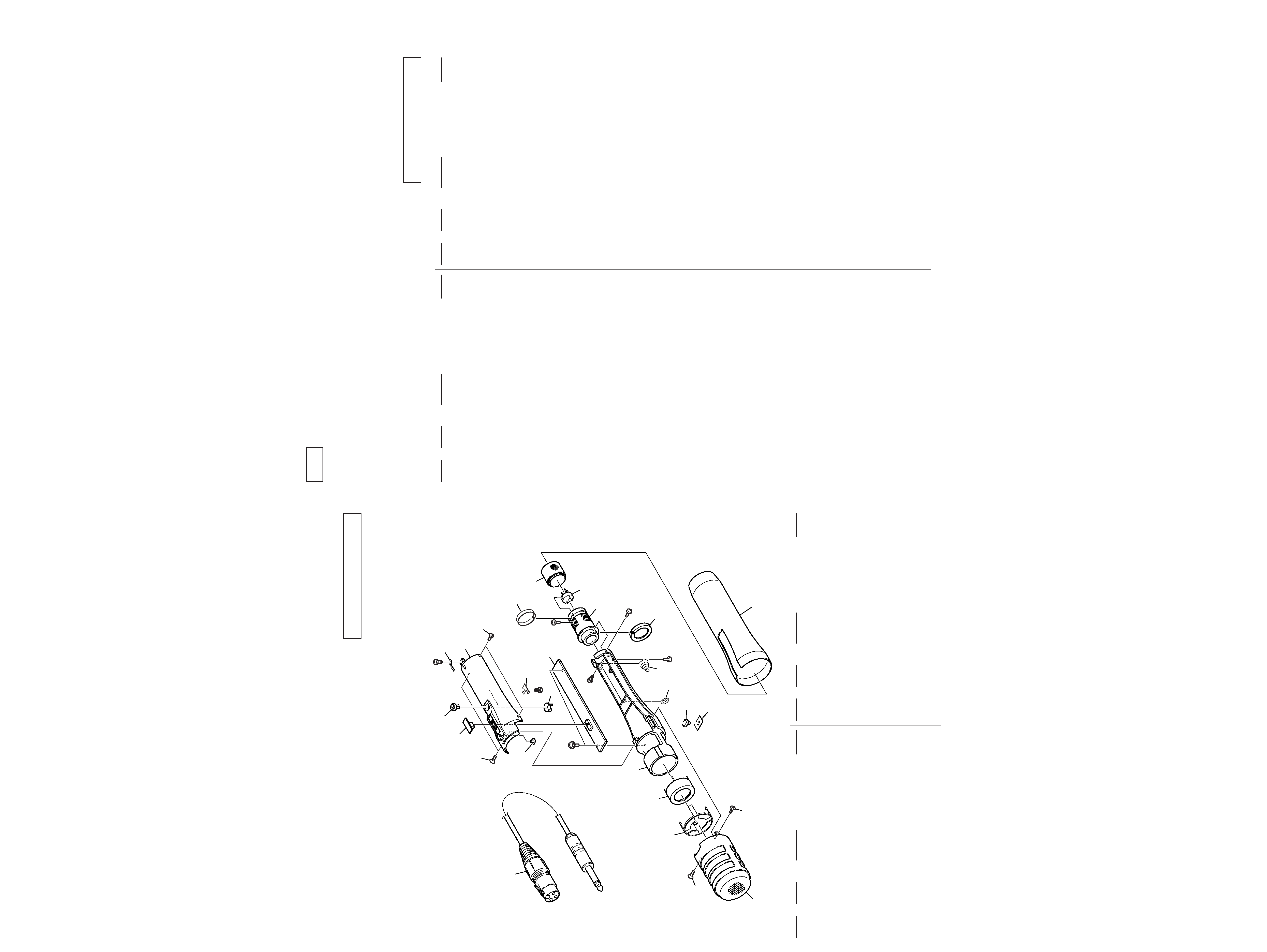
SECTION 4
EXPLODED VIEWS
NOTE:
·
-XX, -X mean standardized parts, so they may
have some differences from the original one.
·
Items marked "*" are not stocked since they
are seldom required for routine service. Some
delay should be anticipated when ordering these
items.
·
The mechanical parts with no reference number
in the exploded views are not supplied.
When indicating parts by reference number,
please include the board name.
23
22
21
20
14
15
18
17
16
15
13
12
11
10
8
9
7
6
5
4
3
2
2
1
19
SW1
#1
#1
#1
CN1
(including ·A)
·A
#2
#3
#4
1
X-2542-164-1 CASE ASSY, MICROPHONE
2
3-736-363-11 TAPPING
* 3
2-545-579-01 STOPPER, CAPSULE
4
A-4540-552-A CAPSULE ASSY
* 5
2-545-573-01 FRAME
* 6
2-545-580-01 PANEL, BLIND
7
2-544-797-01 TERMINAL, PLUS
8
2-544-798-01 TERMINAL, MINUS
9
2-545-576-01 GRIP
10
2-545-578-01 JOINT
* 11
2-545-574-01 SLEEVE, CONNECTOR
* 12
2-545-577-01 RING, SCREW
13
2-545-598-01 LABEL, MODEL NUMBER
* 14
A-4542-563-A AMP BOARD, COMPLETE
15
3-736-363-21 TAPPING
* 16
2-545-572-01 CHASSIS
* 17
2-545-613-01 TERMINAL, GROUND
18
2-545-581-01 KNOB (UPPER), PAD
19
2-545-575-01 KNOB, POWER (POWER/LOW-CUT)
* 20
2-545-582-01 SPRING, PAD
21
2-545-597-01 KNOB (LOWER), PAD
22
2-545-594-01 COVER, LED
23
1-696-448-11 CORD, MICROPHONE (DIA.5) (4 CORE)
CN1
1-563-175-61 CANNON XLR3-14 PIN INSERT
SW1
1-552-190-00 SWITCH, SLIDE (PAD)
#1
7-627-452-38 SCREW,PRECISION +K 2
× 5
#2
7-685-103-19 + PTPWH (2
× 5)
#3
7-627-551-18 SCREW,PRECISION +P 1.4
× 2
#4
7-627-553-68 SCREW,PRECISION +P 2
× 6
Ref. No.
Part No.
Description
Remarks
Ref. No.
Part No.
Description
Remarks
Ref. No.
Part No.
Description
Remarks
Ref. No.
Part No.
Description
Remarks
SECTION 5
ELECTRICAL PARTS LIST
When indicating parts by reference number,
please include the board name.
*
A-4542-563-A AMP BOARD, COMPLETE
********************
< CAPACITOR >
C1
1-130-467-00 MYLAR
470PF
5%
50V
C2
1-130-776-00 MYLAR
0.47uF
10%
63V
C3
1-107-202-00 MICA
10PF
5%
500V
C4
1-113-642-11 TANTAL. CHIP
47uF
20%
10V
C5
1-113-981-11 TANTAL. CHIP
22uF
20%
20V
C6
1-135-073-00 TANTALUM CHIP 0.33uF
10%
35V
C7
1-126-204-11 ELECT CHIP
47uF
20%
16V
C8
1-126-400-11 ELECT CHIP
22uF
20%
35V
C9
1-104-760-11 CERAMIC CHIP
0.047uF
10%
50V
C10
1-104-760-11 CERAMIC CHIP
0.047uF
10%
50V
C11
1-104-760-11 CERAMIC CHIP
0.047uF
10%
50V
C12
1-104-760-11 CERAMIC CHIP
0.047uF
10%
50V
C13
1-113-642-11 TANTAL. CHIP
47uF
20%
10V
C14
1-113-981-11 TANTAL. CHIP
22uF
20%
20V
C15
1-130-776-00 MYLAR
0.47uF
10%
63V
C16
1-104-540-11 FILM CHIP
0.0012uF
5%
50V
< DIODE >
D1
8-719-016-74 DIODE
1SS352
D2
8-719-977-22 DIODE
DTZ9.1
D3
8-719-016-74 DIODE
1SS352
D4
8-719-016-74 DIODE
1SS352
D5
8-719-052-72 LED
CL-220HR-C
(BATTERY CHECK INDICATOR)
D6
8-719-820-41 DIODE
1SS302
D7
8-719-975-40 DIODE
RB411D
< IC >
IC1
8-759-564-83 IC XC6371A701PR
< COIL >
L1
1-412-963-11 INDUCTOR
100uH
L2
1-412-963-11 INDUCTOR
100uH
< TRANSISTOR >
Q1
8-729-203-02 TRANSISTOR
2SK30A-O
Q2
8-729-230-63 TRANSISTOR
2SC4116-YG
Q3
8-729-230-63 TRANSISTOR
2SC4116-YG
< RESISTOR >
R1
1-215-065-00 METAL OXIDE
999.99M
20%
1/8W
R2
1-215-065-00 METAL OXIDE
999.99M
20%
1/8W
R3
1-216-073-00 METAL CHIP
10K
5%
1/10W
R4
1-216-089-91 RES,CHIP
47K
5%
1/10W
R5
1-216-081-00 METAL CHIP
22K
5%
1/10W
R6
1-216-045-00 METAL CHIP
680
5%
1/10W
R7
1-216-077-00 METAL CHIP
15K
5%
1/10W
R8
1-216-033-00 METAL CHIP
220
5%
1/10W
R9
1-216-121-91 RES,CHIP
1M
5%
1/10W
R10
1-216-085-00 METAL CHIP
33K
5%
1/10W
R11
1-216-049-91 RES,CHIP
1K
5%
1/10W
R12
1-216-097-91 RES,CHIP
100K
5%
1/10W
R13
1-216-081-00 METAL CHIP
22K
5%
1/10W
R14
1-216-057-00 METAL CHIP
2.2K
5%
1/10W
R15
1-216-057-00 METAL CHIP
2.2K
5%
1/10W
R16
1-208-291-11 RES,CHIP
4.7M
5%
1/10W
R17
1-216-033-00 METAL CHIP
220
5%
1/10W
R18
1-216-055-00 METAL CHIP
1.8K
5%
1/10W
R19
1-216-073-00 METAL CHIP
10K
5%
1/10W
R20
1-208-291-11 RES,CHIP
4.7M
5%
1/10W
R21
1-208-291-11 RES,CHIP
4.7M
5%
1/10W
R22
1-218-179-11 RES,CHIP
10M
5%
1/10W
R23
1-208-291-11 RES,CHIP
4.7M
5%
1/10W
R24
1-216-097-91 RES,CHIP
100K
5%
1/10W
R25
1-216-089-91 RES,CHIP
47K
5%
1/10W
< SWITCH >
SW2
1-570-056-11 SWITCH, SLIDE (POWER/LOW-CUT)
SW3
1-762-742-31 SWITCH, DETECTION (SMALL TYPE) (PAD)
< TRANSFORMER >
T1
1-431-068-11 TRANSFORMER, OUTPUT
T2
1-429-721-21 TRANSFORMER, DC-DC CONVERTER
************************************************************
MISCELLANEOUS
**************
CN1
1-563-175-61 CANNON XLR3-14 PIN INSERT
SW1
1-552-190-00 SWITCH, SLIDE (DIRECTIVITY)
************************************************************
ACCESSORIES & PACKING MATERIALS
*******************************
1-696-448-11 CORD, MICROPHONE (DIA.5) (4CORE)
2-100-951-04 ADAPTOR, SCREW, STAND (SAD-34) (AEP)
2-100-952-00 ADAPTOR, SCREW, STAND (SAD-35) (AEP)
2-545-055-01 SCREEN, WINDOW
2-545-148-01 PORCH, CARRYING
3-865-087-11 MANUAL, INSTRUCTION
(GERMAN, DUTCH, ITALIAN) (AEP)
3-865-087-21 MANUAL, INSTRUCTION
(ENGLISH, FRENCH, SPANISH)
A-4540-435-A HOLDER ASSY
NOTE:
·
Due to standardization, replacements in the
parts list may be different from the parts
specified in the diagrams or the components
used on the set.
·
-XX, -X mean standardized parts, so they
may have some difference from the original
one.
·
Items marked "*" are not stocked since they
are seldom required for routine service.
Some delay should be anticipated when
ordering these items.
·
CAPACITORS:
uF: µF
·
RESISTORS
All resistors are in ohms.
METAL: metal-film resistor
METAL OXIDE: Metal Oxide-film resistor
F: nonflammable
·
COILS
uH: µH
·
SEMICONDUCTORS
In each case, u: µ, for example:
uA...: µA... , uPA... , µPA... ,
uPB... , µPB... , uPC... , µPC... ,
uPD..., µPD...
AMP
C-357
Sony Corporation
Personal A&V Products Company
99B1660-1
Printed in Japan ©1999.2
Published by Quality Engineering Dept.
(Shinagawa)
9-924-970-11
-- 7 --
-- 8 --