SERVICE MANUAL
Sony Corporation
Personal Audio Group
Published by Sony Engineering Corporation
US Model
PORTABLE DICTATOR
9-879-836-01
2005H1678-1
© 2005.08
Ver. 1.0 2005.08
BM-23MK2
Model Name Using Similar Mechanism
NEW
Tape Transport Mechanism Type
MB-23MK2-101
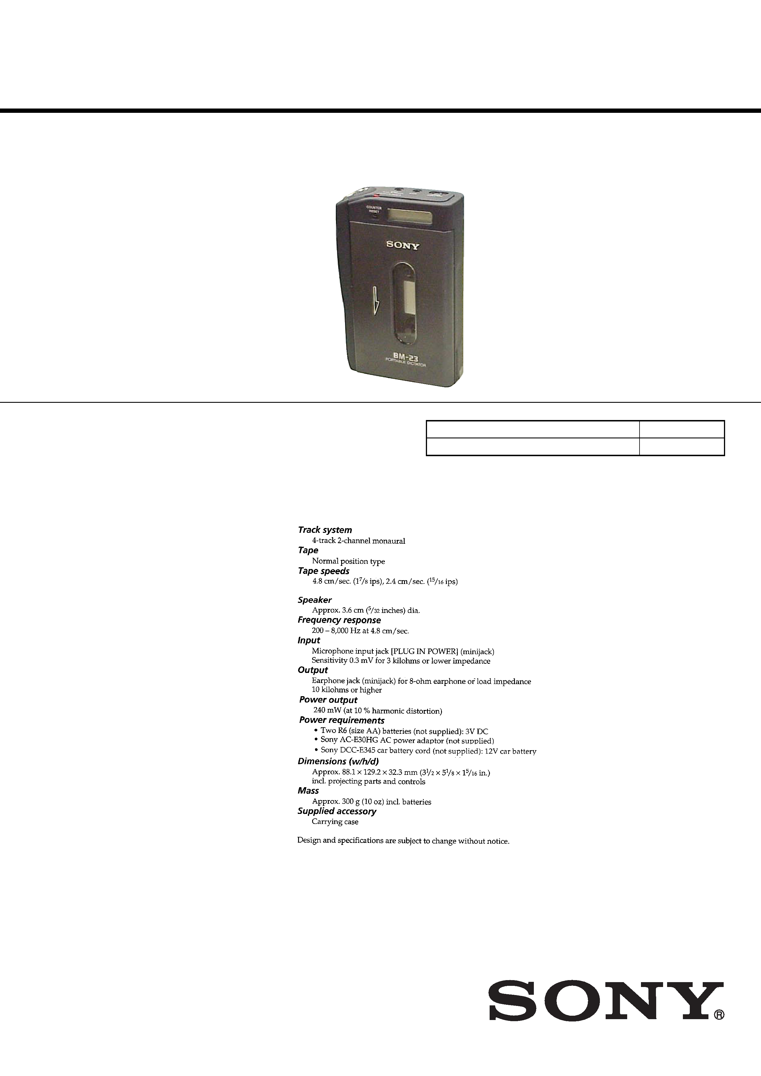
SPECIFICATIONS
2
BM-23MK2
Notes on chip component replacement
·Never reuse a disconnected chip component.
·
Notice that the minus side of a tantalum capacitor may be
damaged by heat.
Flexible Circuit Board Repairing
·Keep the temperature of soldering iron around 270°C during
repairing.
·
Do not touch the soldering iron on the same conductor of the
circuit board (within 3 times).
·
Be careful not to apply force on the conductor when soldering
or unsoldering.
TABLE OF CONTENTS
1.
SERVICING NOTES ............................................... 3
2.
GENERAL ................................................................... 4
3.
DISASSEMBLY
3-1.
Disassembly Flow ...........................................................
5
3-2.
Cabinet (Rear) Block Assembly ......................................
6
3-3.
Control Panel Block Assembly ........................................
7
3-4.
AUDIO Board ..................................................................
8
3-5.
Mechanism Deck (MB-23MK2-101) ..............................
9
3-6.
Holder Panel Assembly ...................................................
9
4.
MECHANICAL ADJUSTMENTS ......................... 10
5.
ELECTRICAL ADJUSTMENTS .......................... 10
6.
DIAGRAMS
6-1.
Block Diagram AUDIO Section ................................ 13
6-2.
Printed Wiring Boards ..................................................... 14
6-3.
Schematic Diagram AUDIO Board (1/4) .................. 15
6-4.
Schematic Diagram AUDIO Board (2/4) .................. 16
6-5.
Schematic Diagram AUDIO Board (3/4) .................. 17
6-6.
Schematic Diagram AUDIO Board (4/4) .................. 18
6-7.
Schematic Diagram LCD Board ............................... 19
7.
EXPLODED VIEWS
7-1.
Cabinet Section ................................................................ 22
7-2.
Chassis Section ................................................................ 23
7-3.
Mechanism Deck Section-1 (MB-23MK2-101) .............. 24
7-4.
Mechanism Deck Section-2 (MB-23MK2-101) .............. 25
8.
ELECTRICAL PARTS LIST .................................. 26
UNLEADED SOLDER
Boards requiring use of unleaded solder are printed with the lead-
free mark (LF) indicating the solder contains no lead.
(Caution: Some printed circuit boards may not come printed with
the lead free mark due to their particular size)
: LEAD FREE MARK
Unleaded solder has the following characteristics.
· Unleaded solder melts at a temperature about 40 °C higher
than ordinary solder.
Ordinary soldering irons can be used but the iron tip has to be
applied to the solder joint for a slightly longer time.
Soldering irons using a temperature regulator should be set to
about 350
°C.
Caution: The printed pattern (copper foil) may peel away if
the heated tip is applied for too long, so be careful!
· Strong viscosity
Unleaded solder is more viscou-s (sticky, less prone to flow)
than ordinary solder so use caution not to let solder bridges
occur such as on IC pins, etc.
· Usable with ordinary solder
It is best to use only unleaded solder but unleaded solder may
also be added to ordinary solder.
CAUTION
Use of controls or adjustments or performance of procedures
other than those specified herein may result in hazardous radiation
exposure.
SAFETY-RELATED COMPONENT WARNING!!
COMPONENTS IDENTIFIED BY MARK 0 OR DOTTED LINE
WITH MARK 0 ON THE SCHEMATIC DIAGRAMS AND IN
THE PARTS LIST ARE CRITICAL TO SAFE OPERATION.
REPLACE THESE COMPONENTS WITH SONY PARTS WHOSE
PART NUMBERS APPEAR AS SHOWN IN THIS MANUAL OR
IN SUPPLEMENTS PUBLISHED BY SONY.
3
BM-23MK2
SECTION 1
SERVICING NOTES
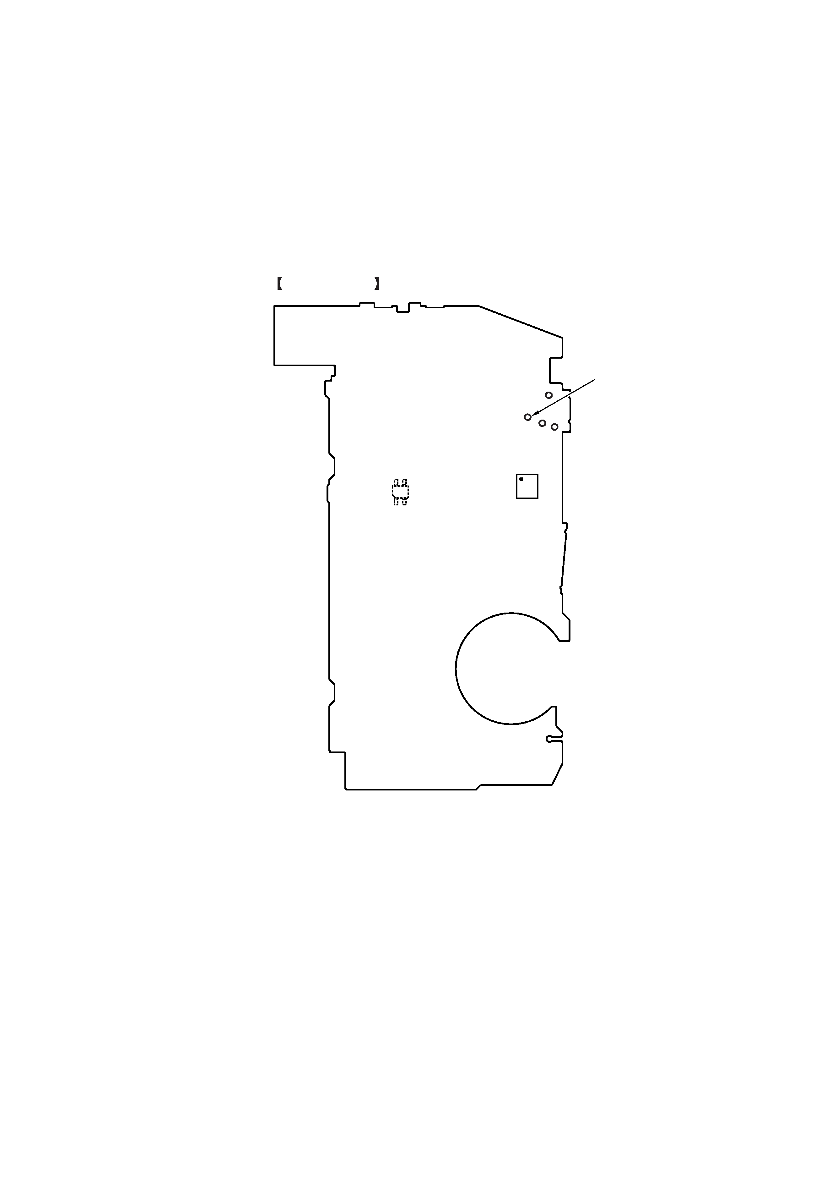
This unit use PH501 (photo coupler) to detect reel rotation.
As PH501 is mounted on the AUDIO board, reel rotation will not be detected if the AUDIO board has been removed.
When performing mechanism deck operation and voltage checks whit the AUDIO board removed, perform them using the following method.
Method:
Connect TP32 of the AUDIO board and GND with a jumper wire.
AUDIO BOARD
(SIDE B)
TP32
IC503
PH501
4
BM-23MK2
SECTION 2
GENERAL
This section is extracted
from instruction manual.
5
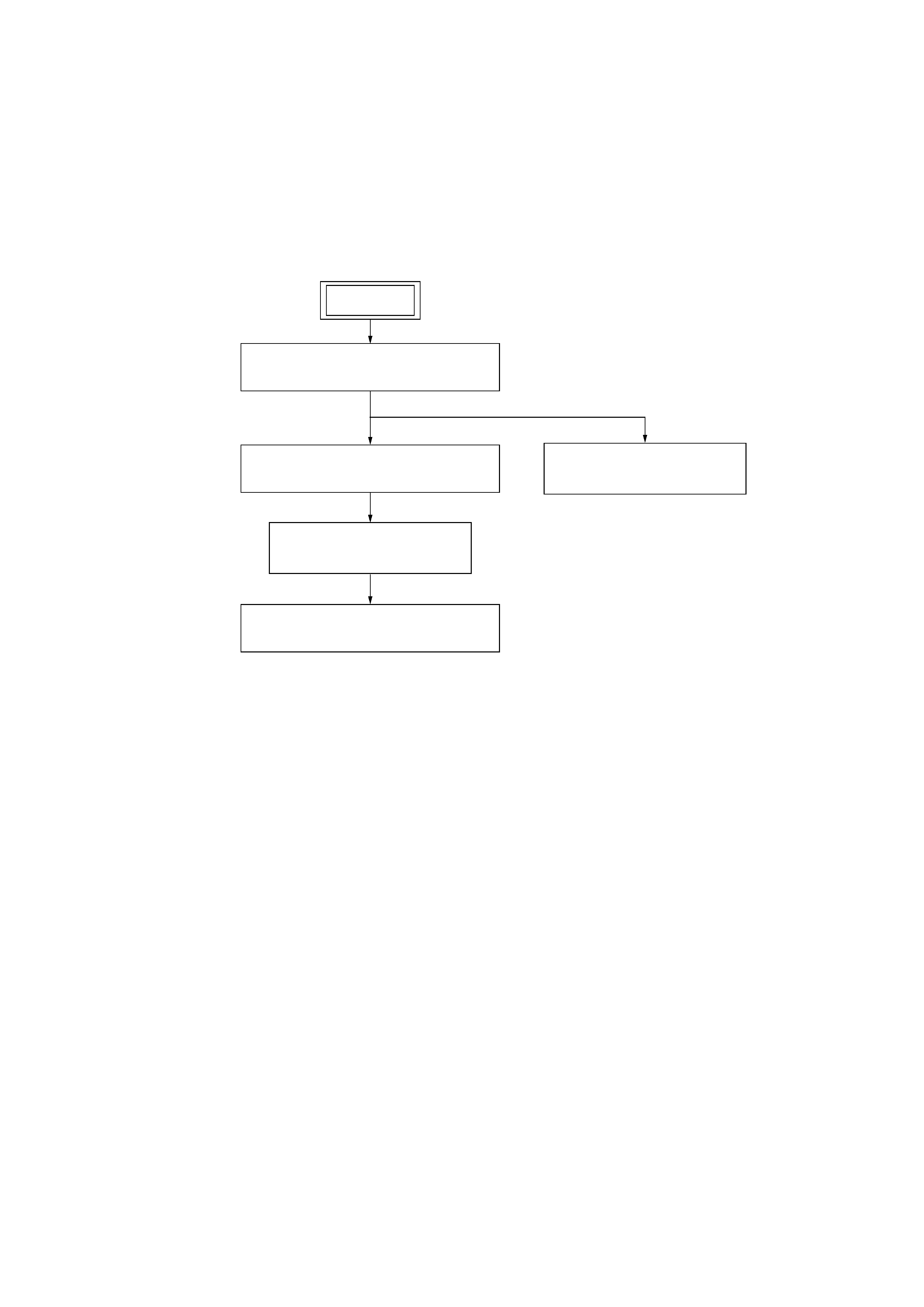
BM-23MK2
SECTION 3
DISASSEMBLY
3-1. DISASSEMBLY FLOW
3-3. CONTROL PANEL BLOCK ASSEMBLY
(Page 7)
3-4. AUDIO BOARD
(Page 8)
3-5. MECHANISM DECK (MB-23MK2-101)
(Page 9)
3-6. HOLDER PANEL ASSEMBLY
(Page 9)
3-2. CABINET (REAR) BLOCK ASSEMBLY
(Page 6)
SET
·This set can be disassembled in the order shown below.