AVD-K800P
US Model
Canadian Model
AEP Model
UK Model
E Model
SERVICE MANUAL
COMPACT AV SYSTEM
Sony Corporation
Audio Group
Published by Sony Engineering Corporation
9-877-319-03
2004I16-1
© 2004.09
Ver 1.2 2004. 09
Model Name Using Similar Mechanism
NEW
Mechanism Type
CDM79-DVBU22
Optical Pick-up Name
DBU-1
SPECIFICATIONS
AUDIO POWER SPECIFICATIONS
POWER OUTPUT AND TOTAL HARMONIC DISTORTION:
With 6 ohm loads, both channels driven, from 120 20,000 Hz; rated 60
watts per channel minimum RMS power , with no more than 0.7 % total
harmonic distortion from 250 milliwatts to rated output (USA model only).
Amplifier section
Rated Power Output at Stereo Mode
60 W + 60 W (6 ohms, at 1 kHz, THD 0.7 %)
Reference Power Output
Front: 100 W/ch (6 ohms at 1 kHz, THD 10 %)
Center*: 100 W (6 ohms at 1 kHz, THD 10 %)
Surround*: 100 W/ch (6 ohms at 1 kHz, THD 10 %)
Sub woofer*: 100 W (6 ohms at 100 Hz, THD 10 %)
* Depending on the sound field settings and the source, there may be no sound output.
Inputs (Analog)
ANALOG IN:
Sensitivity: 500 mV
Impedance: 50 kilohms
Outputs (Analog)
PHONES:
Accepts low- and high-impedance headphones
CD/DVD system
Laser
Semiconductor laser
(DVD:
= 650 nm)
(CD:
= 780 nm)
Emission duration: continuous
Signal format system
NTSC/PAL or NTSC
Frequency response (at 2 CH STEREO mode)
DVD (PCM): 2 Hz to 22 kHz (
±1.0 dB)
CD: 2 Hz to 20 kHz (
±1.0 dB)
Signal-to-noise ratio
More than 80 dB
Harmonic distortion
Less than 0.03 %
FM tuner section
System
PLL quartz-locked digital synthesizer system
Tuning range
North American models: 87.5 108.0 MHz (100 kHz step)
Other models:
87.5 108.0 MHz (50 kHz step)
Antenna
FM wire antenna
Antenna terminals
75 ohms, unbalanced
Intermediate frequency
10.7 MHz
AM tuner section
System
PLL quartz-locked digital synthesizer system
Tuning range
North American models: 530 1,710 kHz (with the interval set at 10 kHz)
531 1,710 kHz (with the interval set at 9 kHz)
European models:
531 1,602 kHz (with the interval set at 9 kHz)
Mexican models:
530 1,610 kHz (with the interval set at 10 kHz)
Other models:
530 1,610 kHz (with the interval set at 10 kHz)
531 1,602 kHz (with the interval set at 9 kHz)
Antenna
AM loop antenna
Intermediate frequency
450 kHz
Video section
Inputs
Video:
1 Vp-p 75 ohms
Outputs
Video:
1 Vp-p 75 ohms
Component: Y: 1 Vp-p 75 ohms
PB/CB: 0.7 Vp-p 75 ohms
PR/CR: 0.7 Vp-p 75 ohms
General
Power requirements
North American and Mexican models:
120 V AC, 60 Hz
European models:
230 V AC, 50/60 Hz
Other models:
120/220 V AC, 50/60 Hz
Power consumption
Canadian models:
240 VA
Other models:
190 W
Power consumption (at Power Saving Mode):
0.5 W
Dimensions (approx.)
430
× 170 × 450 mm (17 × 6 7/8 × 17 7/8 inches)
(w/h/d) incl. projecting parts
Mass (approx.)
11.5 kg (25 lb 6 oz.)
Operating temperature
5°C to 35°C (41°F to 95°F)
Operating humidity
5 % to 90 %
Design and specifications are subject to change without notice.
This system incorporates with Dolby* Digital and Dolby Pro Logic (II) adaptive matrix
surround decoder and the DTS** Digital Surround System.
*
Manufactured under license from Dolby Laboratories.
"Dolby", "Pro Logic" and the double-D symbol are trademarks of Dolby Laboratories.
** Manufactured under license from Digital Theater Systems, Inc.
"DTS" and "DTS Digital Surround" are trademarks of Digital Theater Systems, Inc.
AVD-K800P is the amplifier, CD/DVD and tuner system in HT-C800DP.
2
AVD-K800P
LEAKAGE
The AC leakage from any exposed metal part to earth Ground and
from all exposed metal parts to any exposed metal part having a
return to chassis, must not exceed 0.5 mA (500 microampers).
Leakage current can be measured by any one of three methods.
1.
A commercial leakage tester, such as the Simpson 229 or RCA
WT-540A. Follow the manufacturers' instructions to use these
instruments.
2.
A battery-operated AC milliammeter. The Data Precision 245
digital multimeter is suitable for this job.
3.
Measuring the voltage drop across a resistor by means of a
VOM or battery-operated AC voltmeter. The "limit" indication
is 0.75 V, so analog meters must have an accurate low-voltage
scale. The Simpson 250 and Sanwa SH-63Trd are examples of
a passive VOM that is suitable. Nearly all battery operated
digital multimeters that have a 2V AC range are suitable. (See
Fig. A)
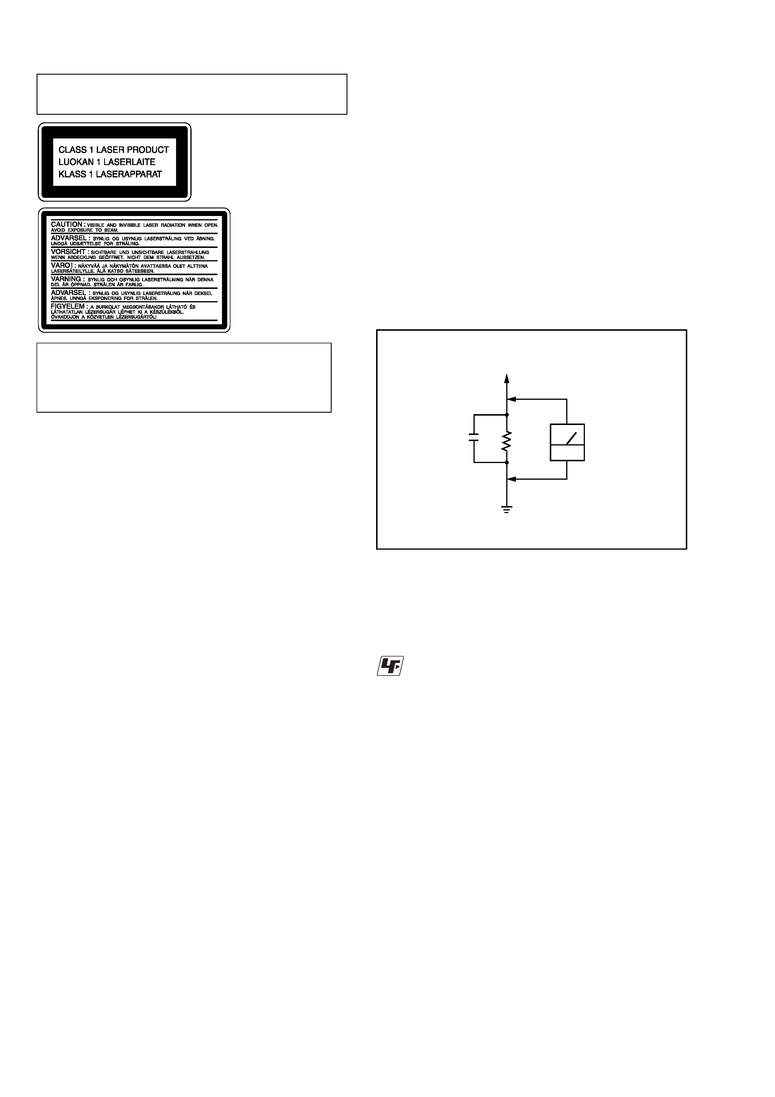
Fig. A. Using an AC voltmeter to check AC leakage.
0.15
µF
To Exposed Metal
Parts on Set
1.5k
AC
voltmeter
(0.75V)
Earth Ground
CAUTION
Use of controls or adjustments or performance of procedures
other than those specified herein may result in hazardous
radiation exposure.
Notes on chip component replacement
·Never reuse a disconnected chip component.
· Notice that the minus side of a tantalum capacitor may be
damaged by heat.
Flexible Circuit Board Repairing
·Keep the temperature of soldering iron around 270°C
during repairing.
· Do not touch the soldering iron on the same conductor of the
circuit board (within 3 times).
· Be careful not to apply force on the conductor when soldering
or unsoldering.
SAFETY CHECK-OUT
After correcting the original service problem, perform the following
safety checks before releasing the set to the customer:
Check the antenna terminals, metal trim, "metallized" knobs, screws,
and all other exposed metal parts for AC leakage. Check leakage as
described below.
Laser component in this product is capable of emitting radiation
exceeding the limit for Class 1.
This appliance is classified as a
CLASS 1 LASER product.
The
CLASS
1
LASER
PRODUCT MARKING is
located on the rear exterior.
SAFETY-RELATED COMPONENT WARNING!!
COMPONENTS IDENTIFIED BY MARK 0 OR DOTTED LINE WITH
MARK 0 ON THE SCHEMATIC DIAGRAMS AND IN THE PARTS
LIST ARE CRITICAL TO SAFE OPERATION. REPLACE THESE
COMPONENTS WITH SONY PARTS WHOSE PART NUMBERS
APPEAR AS SHOWN IN THIS MANUAL OR IN SUPPLEMENTS
PUBLISHED BY SONY.
Unleaded solder
Boards requiring use of unleaded solder are printed with the lead-
free mark (LF) indicating the solder contains no lead.
(Caution: Some printed circuit boards may not come printed with
the lead free mark due to their particular size.)
: LEAD FREE MARK
Unleaded solder has the following characteristics.
· Unleaded solder melts at a temperature about 40
°C higher than
ordinary solder.
Ordinary soldering irons can be used but the iron tip has to be
applied to the solder joint for a slightly longer time.
Soldering irons using a temperature regulator should be set to
about 350
°C.
Caution: The printed pattern (copper foil) may peel away if the
heated tip is applied for too long, so be careful!
· Strong viscosity
Unleaded solder is more viscous (sticky, less prone to flow) than
ordinary solder so use caution not to let solder bridges occur such
as on IC pins, etc.
· Usable with ordinary solder
It is best to use only unleaded solder but unleaded solder may
also be added to ordinary solder.
ATTENTION AU COMPOSANT AYANT RAPPORT
À LA SÉCURITÉ!
LES COMPOSANTS IDENTIFÉS PAR UNE MARQUE 0 SUR LES
DIAGRAMMES SCHÉMATIQUES ET LA LISTE DES PIÈCES SONT
CRITIQUES POUR LA SÉCURITÉ DE FONCTIONNEMENT. NE
REMPLACER CES COMPOSANTS QUE PAR DES PIÈSES SONY
DONT LES NUMÉROS SONT DONNÉS DANS CE MANUEL OU
DANS LES SUPPÉMENTS PUBLIÉS PAR SONY.
The following caution
label is located inside
the apparatus.
3
AVD-K800P
NOTES ON HANDLING THE OPTICAL PICK-UP BLOCK
OR BASE UNIT
The laser diode in the optical pick-up block may suffer electrostatic
break-down because of the potential difference generated by the
charged electrostatic load, etc. on clothing and the human body.
During repair, pay attention to electrostatic break-down and also
use the procedure in the printed matter which is included in the
repair parts.
The flexible board is easily damaged and should be handled with
care.
NOTES ON LASER DIODE EMISSION CHECK
The laser beam on this model is concentrated so as to be focused on
the disc reflective surface by the objective lens in the optical pick-
up block. Therefore, when checking the laser diode emission,
observe from more than 30 cm away from the objective lens.
LASER DIODE AND FOCUS SEARCH OPERATION
CHECK
Carry out the "S curve check" in "CD section adjustment" and check
that the S curve waveform is output several times.
MODEL IDENTIFICATION
-- BACK PANEL --
Part No.
·Abbreviation
E51 : Chilean and peruvian models.
Model
US and E51 models
Canadian model
Mexican model
AEP model
UK model
PARTS No.
4-244-942-0s
4-244-942-1s
4-244-942-2s
4-244-942-3s
4-244-942-4s
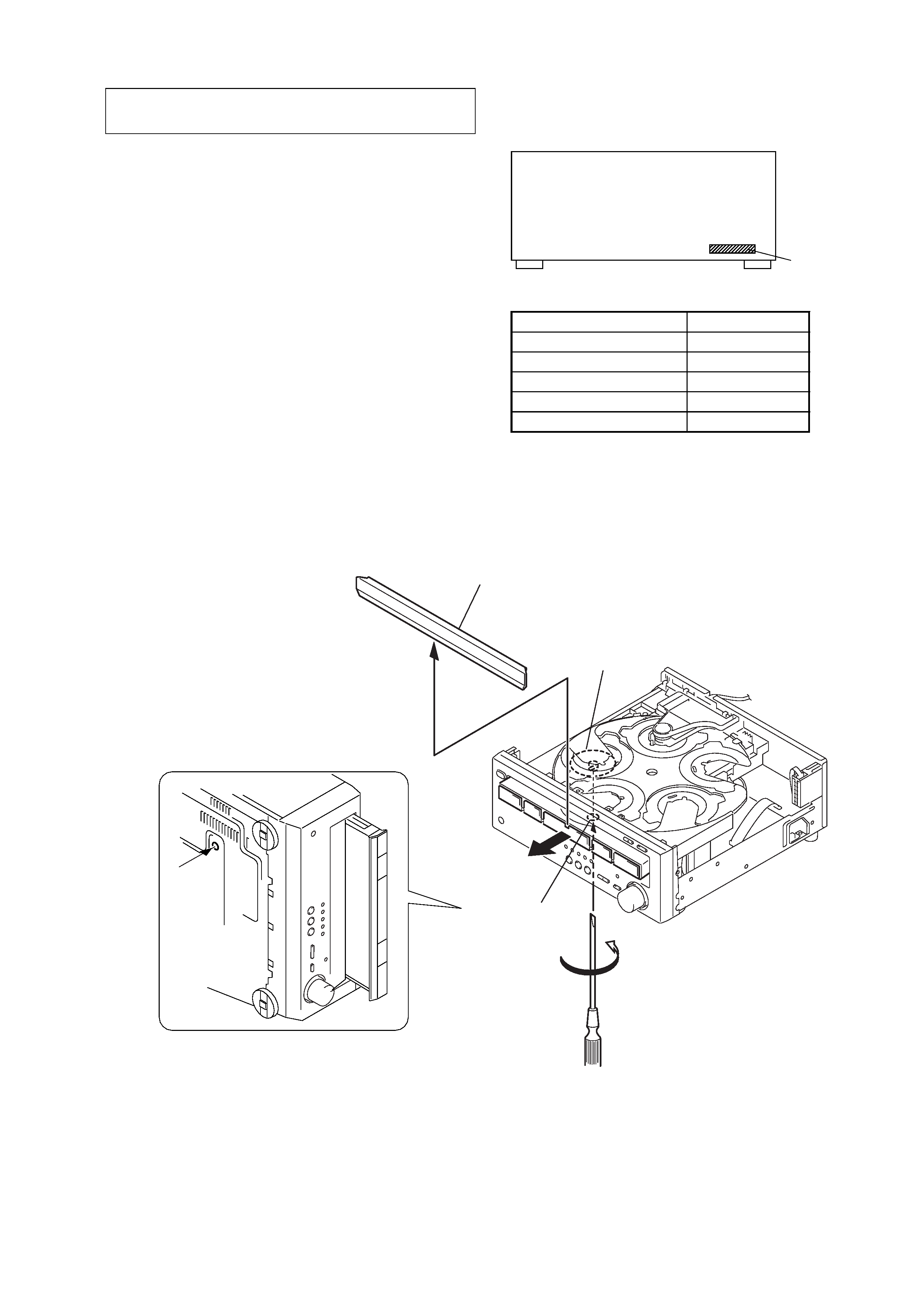
HOW TO OPEN THE DISC TRY WHEN POWER SWITCH TURNS OFF
3
loading (panel)
2
table
1
Turn the gear (shaft) in the
direction of the arrow.
gear (shaft)
hole of chassis
4
AVD-K800P
1. GENERAL ·········································································· 5
2. DISASSEMBLY
2-1. Case ··············································································· 7
2-2. Loading (PANEL) ························································· 8
2-3. CD Mechanism Deck (CDM79-DVBU22) ··················· 8
2-4. Front Panel Assy ···························································· 9
2-5. DISPLAY Board, OPEN/CLOSE Board,
POWER SWITCH Board, HP Board ···························· 9
2-6. Tuner Unit (TM301), I/O Board ·································· 10
2-7. DMB03 Board ····························································· 10
2-8. DC Fan (FAN1) ··························································· 11
2-9. MAIN Board ······························································· 11
2-10. Table Assy ··································································· 12
2-11. SE-130 Board ······························································ 13
2-12. DC Motor (M001) ······················································· 14
2-13. Pickup Unit Section ····················································· 14
2-14. RF Board ····································································· 15
3. TEST MODE ··································································· 16
4. DIAGRAMS
4-1. Circuit Board Location ················································ 25
4-2. Block Diagrams
-- RF SERVO Section -- ··········································· 26
-- VIDEO Section -- ·················································· 27
-- AUDIO Section -- ················································· 28
-- AMP Section -- ····················································· 29
-- POWER Section -- ················································ 30
4-3. Printed Wiring Board -- RF Section -- ······················ 31
4-4. Schematic Diagram -- RF Section -- ························ 32
4-5. Printed Wiring Board -- DMB Section (SIDE A) -- · 33
4-6. Printed Wiring Board -- DMB Section (SIDE B) -- · 34
4-7. Schematic Diagram -- DMB Section (1/8) -- ··········· 35
4-8. Schematic Diagram -- DMB Section (2/8) -- ··········· 36
4-9. Schematic Diagram -- DMB Section (3/8) -- ··········· 37
4-10. Schematic Diagram -- DMB Section (4/8) -- ··········· 38
4-11. Schematic Diagram -- DMB Section (5/8) -- ··········· 39
4-12. Schematic Diagram -- DMB Section (6/8) -- ··········· 40
4-13. Schematic Diagram -- DMB Section (7/8) -- ··········· 41
4-14. Schematic Diagram -- DMB Section (8/8) -- ··········· 42
4-15. Printed Wiring Board -- I/O Section -- ····················· 43
4-16. Schematic Diagram -- I/O Section -- ························ 44
4-17. Printed Wiring Board -- MAIN Section -- ················ 45
4-18. Schematic Diagram -- MAIN Section (1/3) -- ·········· 46
4-19. Schematic Diagram -- MAIN Section (2/3) -- ·········· 47
4-20. Schematic Diagram -- MAIN Section (3/3) -- ·········· 48
4-21. Printed Wiring Board
-- VOLTAGE SELECTOR, LOADING Section -- ··· 49
4-22. Schematic Diagram -- LOADING Section -- ··········· 50
4-23. Printed Wiring Board -- DISPLAY Section -- ·········· 51
4-24. Schematic Diagram -- DISPLAY Section -- ············· 52
4-25. IC Block Diagrams ····················································· 54
4-26. IC Pin Function Description ······································· 61
5. EXPLODED VIEWS
5-1. Case Section ································································ 70
5-2. Front Panel Section ····················································· 71
5-3. Chassis Section ···························································· 72
5-4. CD Mechanism Deck Section-1 (CDM79-DVBU22) · 73
5-5. CD Mechanism Deck Section-2 (CDM79-DVBU22) · 74
6. ELECTRICAL PARTS LIST ······································· 75
Ver 1.1
TABLE OF CONTENTS
NOTES ON DMB03 BOARD EXCHANGE
If a DMB03 board is exchanged, "DRIVE AUTO ADJUSTMENT"
may be unable to be performed. In this case, initialize a memory in
the following procedure.
1. Starting Test Mode (see page 17).
2. Press the 2 button of remote commander to set the Drive
Manual Operation (see page 19).
3. Press the 6 button of remote commander to set the Memory
Check (see page 21).
4. Press the [CLEAR] button of remote commander to initialize
a memory.
AUTO SERVO ADJUSTMENT
After parts related to the servo circuit (RF amplifier (IC001), DSP
(IC509), motor driver (IC501), EEPROM (IC903) so on) are
replaced, re-adjusting the servo circuit is necessary. Select "ALL"
at "1. DRIVE AUTO ADJUSTMENT" (Refer to page 18 in TEST
MODE) and adjust DVD-SL (single layer), CD and DVD-DL (dual
layer).
RFMON Level Check
Perform a RFMON level check before exchanging optical pick-up.
Measurement Point: DMB03 board CN501
13pin (RFMON) -- 29pin (AGND)
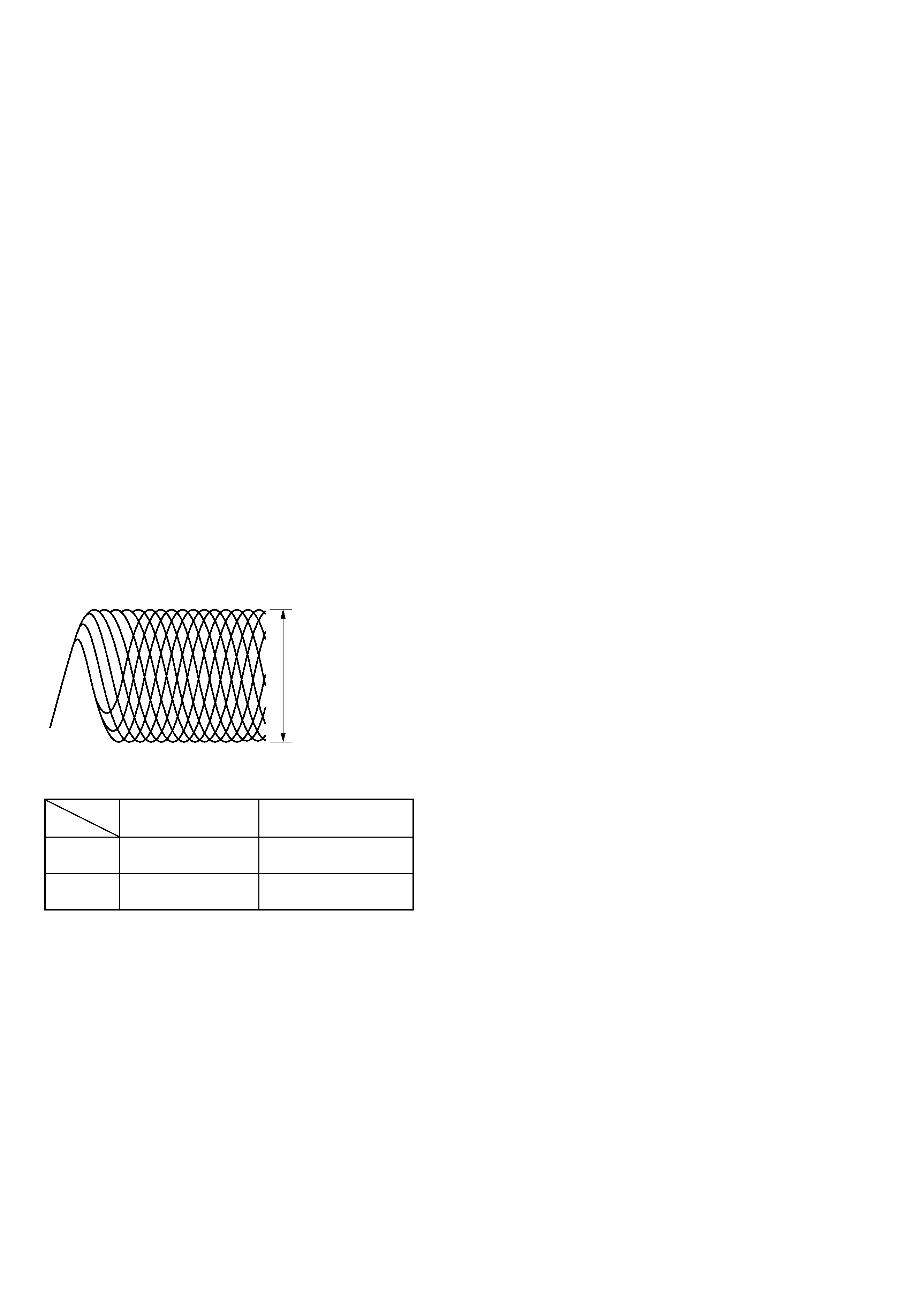
RFMON signal waveform
· Standard value
Test Disc
RFMON level
Standard Value
DVD
TDV-520CSO
1.09
± 0.2Vp-p
(J-2501-236-A)
CD
LUV-P01
1.05
± 0.2Vp-p
(4-999-032-01)
VOLT/DIV: 200 mV
TIME/DIV: 500 ns
RFMON level
5
AVD-K800P
SECTION 1
GENERAL
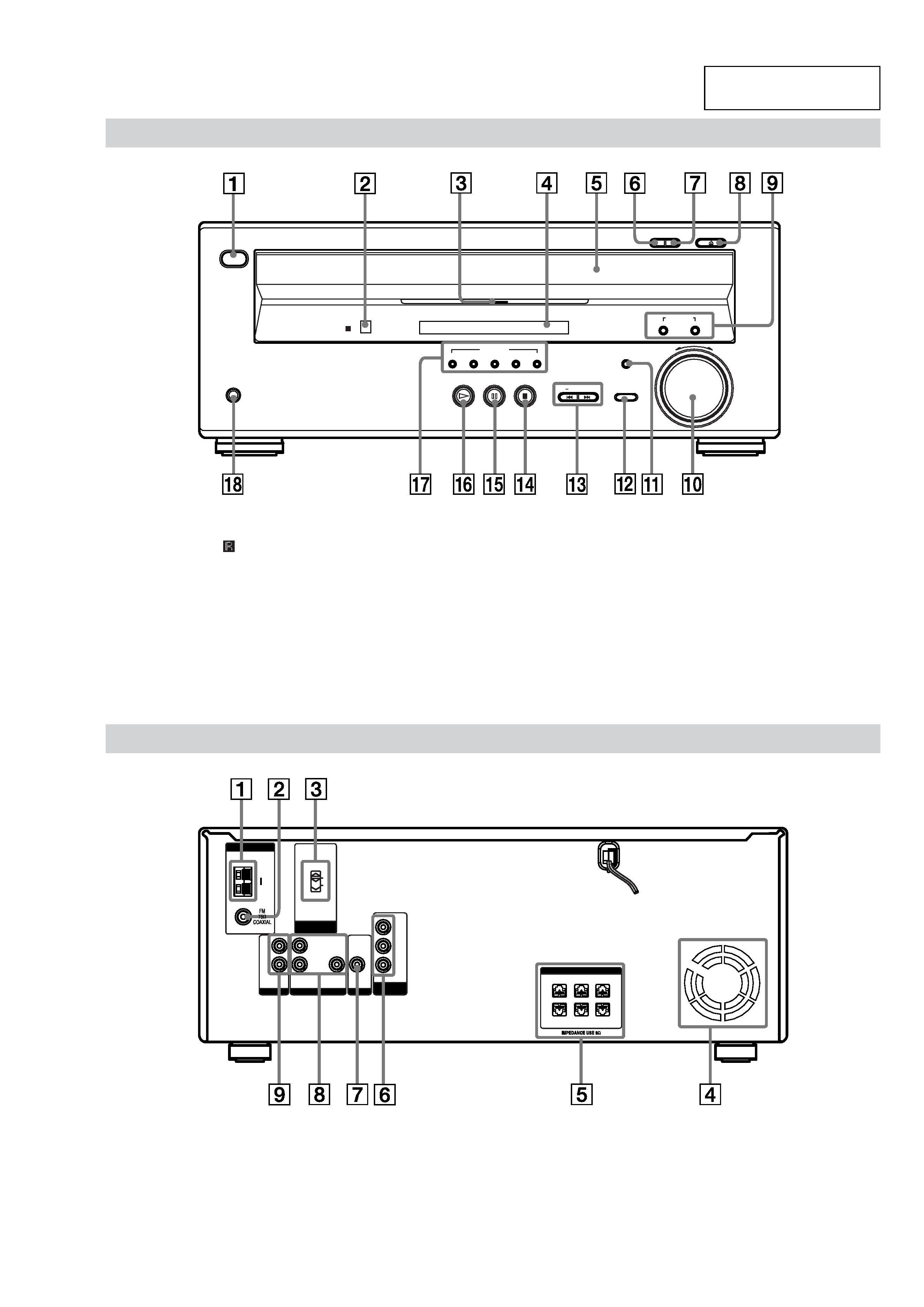
Front Panel
?/1
PHONES
DISC SELECT
MULTI CHANNEL DECODING
12345
SUB WOOFER
LEVEL
FUNCTION
PRESET +
+
MASTER
VOLUME
SOUND FIELD
EX-CHANGE DISC SKIP
OPEN/CLOSE
+
1 ?/1 (power switch) (29)
2
(remote sensor) (18)
3 MULTI CHANNEL DECODING
indicator (49)
4 Front panel display (12)
5 Disc tray (29)
6 EX-CHANGE (30)
7 DISC SKIP (29)
8 A OPEN/CLOSE (29)
9 SOUND FIELD +/ (50)
0 MASTER VOLUME control (29, 70)
qa SUB WOOFER LEVEL (69)
qs FUNCTION (29)
qd PRESET +/, ./> (27, 30)
qf x (stop) (30)
qg S (pause) (30)
qh H (play) (29)
qj DISC SELECT 1 5 (29)
qk PHONES jack (29)
Rear Panel
L
R
y
AM
AUDIO IN
VIDEO IN
FRONT R
SURR R SUB WOOFER SURR L
+
+
+
+
+
+
FRONT L
CENTER
SPEAKERS
VOLTAGE
SELECTOR
Y
TV
ANTENNA
120V
220V
L
R
AUDIO IN
VIDEO
MONITOR
COMPONENT
VIDEO OUT
VIDEO OUT
PR/CR
PB/CB
1 AM antenna terminals (22)
2 FM 75
COAXIAL antenna jack (22)
3 VOLTAGE SELECTOR (only for
equipped models) (25)
4 Ventilation holes (fan) (74)
5 SPEAKERS jacks (20)
6 COMPONENT VIDEO OUT jacks (24)
7 MONITOR (VIDEO OUT) jack (24)
8 VIDEO (AUDIO L/R IN/VIDEO IN)
jacks (24)
9 TV (AUDIO L/R IN) jacks (24)
This section is extracted
from instruction manual.