MICROFILM
SERVICE MANUAL
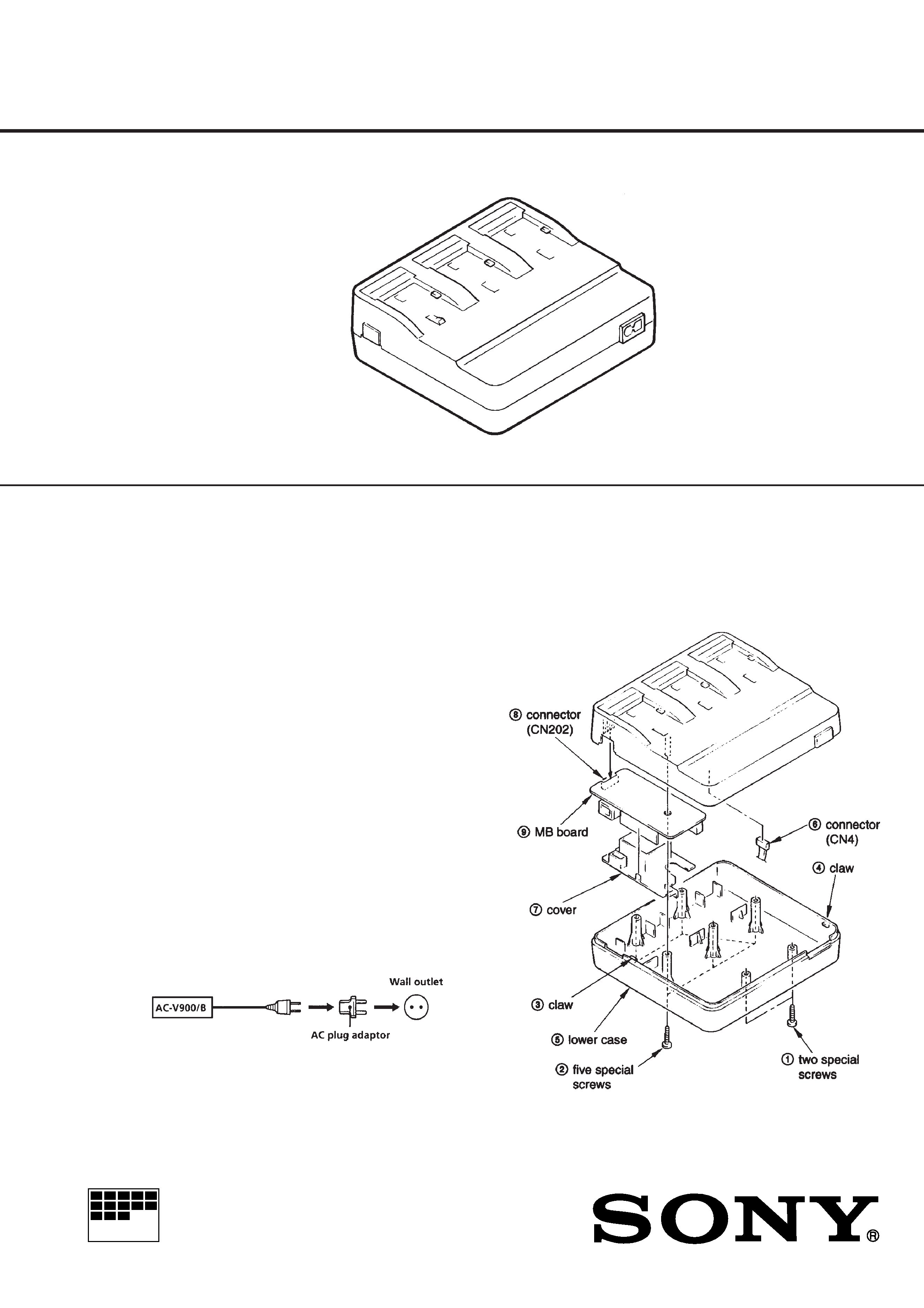
AC-V900/B
SPECIFICATIONS
AC POWER ADAPTOR
US Model
Canadian Model
AEP Model
UK Model
Power requirements
100 240 V AC, 50/60Hz
Power consumption
70W
Charge mode:
95 VA (100 V AC), 125 VA (240 V
AC)
Operating mode:
41 VA (100 V AC), 58 VA (240 V AC)
Output voltage
DC CUT:
8.4 V, 1.8A in operating mode
Battery charge terminal:
8.4 V, 1.4 A in charge mode
× 3
Application
Sony battery pack NP-500H/520/
F530/720/F730/F930/F550/F750/
F950)
Operating temperature
0 º C to 40 ºC (32 ºF to 104 ºF )
Storage temperature
20 º C to 60 ºC (4 ºF to 140 ºF )
Dimensions
Approx. 169
× 58 × 153 mm (w/h/d)
(6 3/4
× 2 3/8 × 6 1/8 inches)
including projecting parts
Mass
Approx. 650g (1lb 6 oz)
Supplied accessory
Connecting cord DK-715 (1)
AC power cord (European model (2),
Other country models (1))
Design and specification are subject to change without notice.
Use a commercially available AC plug adaptor, if necessary, depending
on the design of the wall outlet.
Discard your 9-973-926-11 Service Manual
for AC-V900/B Model previously issued.
This Service manual contains it.
SECTION 1
DISASSEMBLY
Note: Follow the disassembly procedure in the numerical order
given.
1-1.
MB BOARD REMOVAL
Ver 1.1 1998. 4
2
Sony Corporation
Personal A&V Products Company
9-973-926-12
98D0512-1
Printed in Japan © 1998. 4
Published by Service and Safety
Engineering Dept. (Osaki East)
! 1
A-4946-029-A MB BOARD, COMPLETE (ACC-36UC) (US,
Canadian)
! 1
A-4946-032-A MB BOARD, COMPLETE (ACC-36CE) (AEP, UK)
2
A-4925-971-A CH BOARD, COMPLETE (ACC-29)
3
2-409-117-01 CASE, UPPER
4
2-439-769-01 LABEL, BATTERY, SONY (US, Canadian)
5
2-433-211-01 PLATE, LIGHT GUIDE
! 6
A-4946-032-A MB BOARD, COMPLETE (ACC-36CE)
! 7
A-4946-031-A F BOARD, COMPLETE (ACC-36UC)
(US, Canadian)
! 7
A-4946-034-A F BOARD, COMPLETE (ACC-36CE) (AEP, UK)
8
2-434-468-01 SCREW, 2.6X8, B TIGHT
9
2-409-118-01 CASE, LOWER
10
3-946-773-01 SCREW, SPECIAL TAPPING
CN302
1-694-110-12 TERMINAL BOARD, BATTERY LITHIUM
! F1
1-532-465-31 FUSE (250V/3.15A)
ACCESSORIES & PACKING MATERIALS
********************************
!
1-690-827-21 CORD, POWER (AEP)
1-769-635-21 CORD, CONNECTION (DK715)
!
1-775-549-21 CORD, POWER (US, Canadian)
3-859-221-13 MANUAL, INSTRUCTION (ENGLISH, FRENCH,
GERMAN, ITALIAN)
Ref. No.
Part No.
Description
Remark
The components identified by
mark
! or dotted line with
mark
! are critical for safety.
Replace only with part num-
ber specified.
Les composants identifiés par une
marque
! sont critiques pour la
sécurité.
Ne les remplacer que par une pièce
portant le numéro spécifié.
SECTION 2
REPAIR PARTS LIST
2-1.
EXPLODED VIEWS
SECTION 3
CHECK
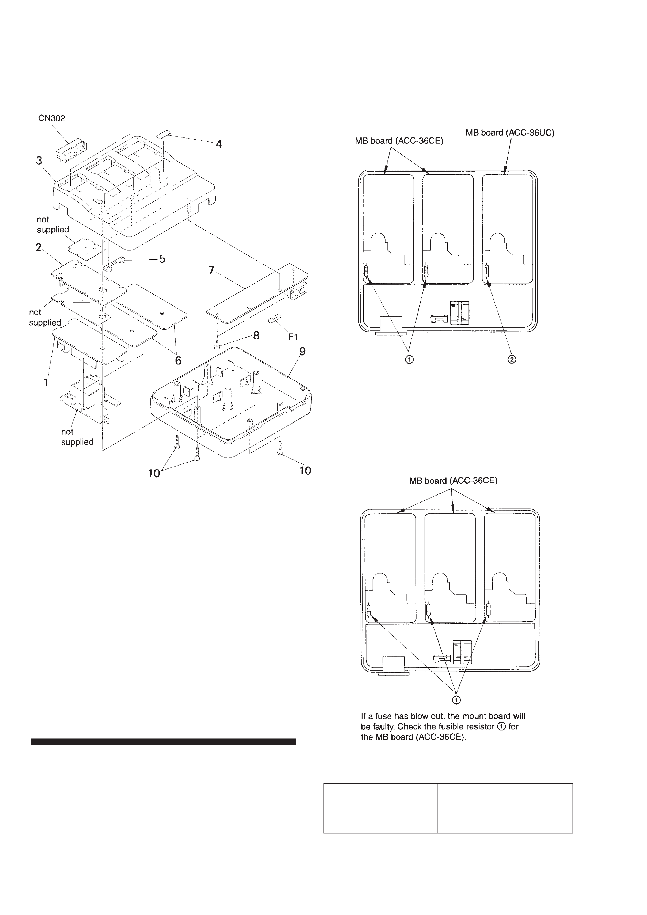
3-1. CHECK THE FUSE AND FUSIBLE RE-
SISTOR
3-1-1.
US, Canadian model
If a fuse has blow out, the mount board will be faulty. Check the
fusible resistor 1 for the MB board (ACC-36CE), or fuse 2 for
the MB board (ACC-36 UC).
3-1-2.
AEP, UK model