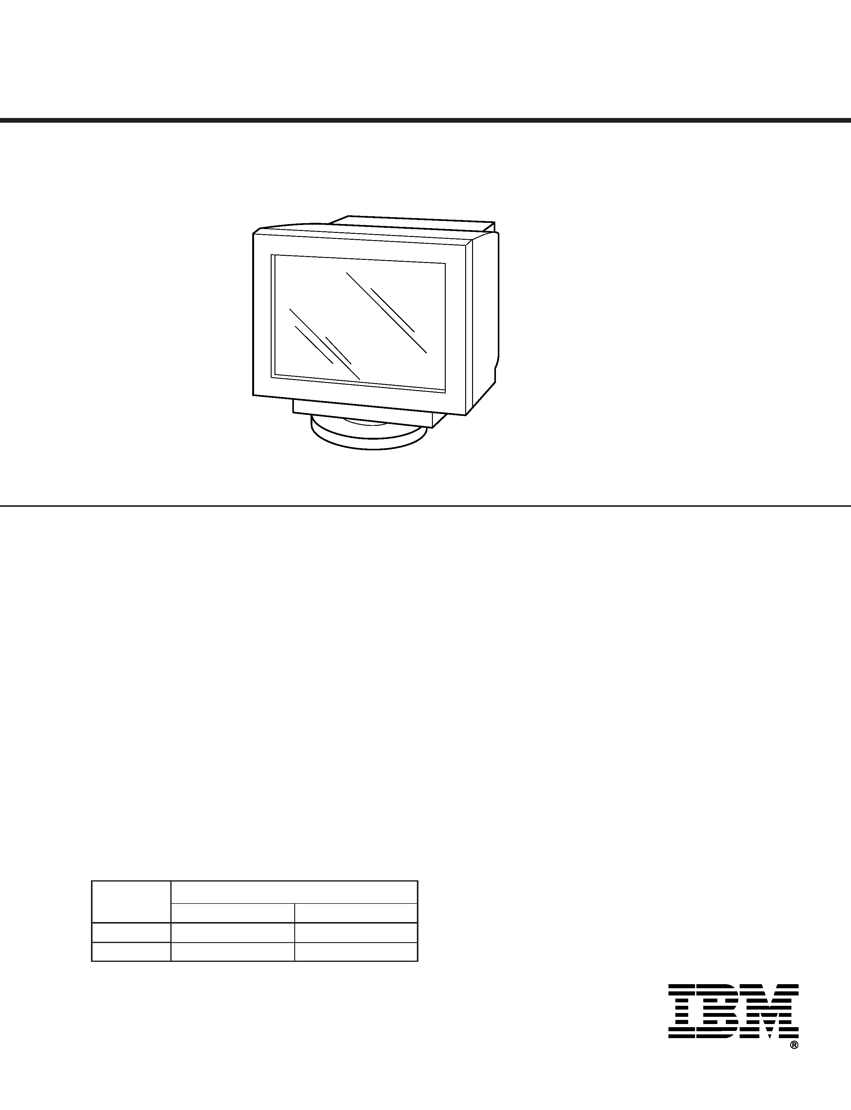
CHASSIS
SPECIFICATIONS
SERVICE MANUAL
F99
TRINITRON® COLOR
GRAPHIC DISPLAY
6551-T3N/6551-U3N
AEP Model
Chassis No. SCC-L40A-A (6551-T3N)
Chassis No. SCC-L40B-A (6551-U3N)
MODEL
SPEC.
BODY COLOR
DEST.
6551-T3N
WHITE TYPE
AEP
6551-U3N
BLACK TYPE
AEP
Picture tube
0.24 mm aperture grille pitch
19 inches measured diagonally
90-degree deflection
Viewable image size
Approx. 365
× 274 mm (w/h)
(14 3/8
× 10 7/8 inches)
18.0" viewable diagonal
Resolution
Horizontal: Max. 1600 dots
Vertical: Max. 1200 lines
Standard image area
Approx. 352
× 264 mm (w/h)
(13 7/8
× 10 1/2 inches)
Deflection frequency*
Horizontal: 30 to 107kHz
Vertical: 48 to 120 Hz
256
< Total Line < 2048
AC input voltage/current
220 to 240 V, 50 60 Hz, Max. 1.0 A
Power consumption
Max. 140 W
Operating temperature 10
°C to 40°C
Dimensions
Approx. 462
× 462 × 474 mm
(w/h/d)
(18 1/4
× 18 1/4 × 18 3/4 inches)
Mass
Approx. 27 kg (59 lb 8 oz)
* Recommended horizontal and vertical timing condition
· Horizontal sync width should be more than 1.0
µsec.
· Horizontal blanking width should be more than
3.0
µsec.
· Vertical blanking width should be more than 450
µsec.
Design and specifications are subject to change without
notice.
6551-T3N/6551-U3N
2
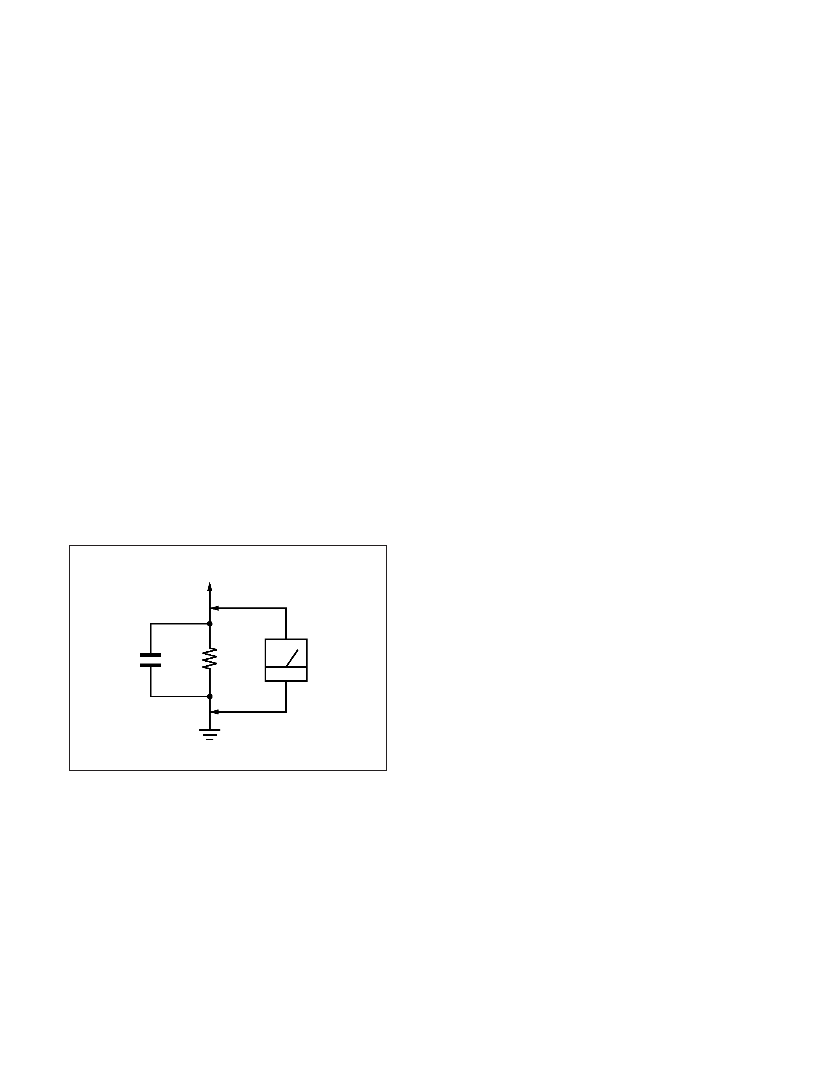
LEAKAGE TEST
The AC leakage from any exposed metal part to earth ground
and from all exposed metal parts to any exposed metal part hav-
ing a return to chassis, must not exceed 0.5 mA (500
microampers).
Leakage current can be measured by any one of three methods.
1. A commercial leakage tester, such as the Simpson 229 or
RCA WT-540A. Follow the manufacturers' instructions to
use these instruments.
2. A battery-operated AC milliammeter. The Data Precision
245 digital multimeter is suitable for this job.
3. Measuring the voltage drop across a resistor by means of a
VOM or battery-operated AC voltmeter. The "limit" indica-
tion is 0.75 V, so analog meters must have an accurate low-
voltage scale. The Simpson 250 and Sanwa SH-63Trd are
examples of a passive VOMs that are suitable. Nearly all
battery operated digital multimeters that have a 2 V AC
range are suitable. (See Fig. A)
WARNING!!
NEVER TURN ON THE POWER IN A CONDITION IN
WHICH THE DEGAUSS COIL HAS BEEN REMOVED.
SAFETY-RELATED COMPONENT WARNING!!
COMPONENTS IDENTIFIED BY SHADING AND MARK
¡ ON THE SCHEMATIC DIAGRAMS, EXPLODED
VIEWS AND IN THE PARTS LIST ARE CRITICAL FOR
SAFE OPERATION. REPLACE THESE COMPONENTS
WITH SONY PARTS WHOSE PART NUMBERS AP-
PEAR AS SHOWN IN THIS MANUAL OR IN SUPPLE-
MENTS PUBLISHED BY SONY. CIRCUIT ADJUST-
MENTS THAT ARE CRITICAL FOR SAFE OPERATION
ARE IDENTIFIED IN THIS MANUAL. FOLLOW THESE
PROCEDURES WHENEVER CRITICAL COMPONENTS
ARE REPLACED OR IMPROPER OPERATION IS
SUSPECTED.
After correcting the original service problem, perform the fol-
lowing safety checks before releasing the set to the customer:
1. Check the area of your repair for unsoldered or poorly-sol-
dered connections. Check the entire board surface for solder
splashes and bridges.
2. Check the interboard wiring to ensure that no wires are
"pinched" or contact high-wattage resistors.
3. Check that all control knobs, shields, covers, ground straps,
and mounting hardware have been replaced. Be absolutely
certain that you have replaced all the insulators.
4. Look for unauthorized replacement parts, particularly tran-
sistors, that were installed during a previous repair. Point
them out to the customer and recommend their replacement.
5. Look for parts which, though functioning, show obvious
signs of deterioration. Point them out to the customer and
recommend their replacement.
6. Check the line cords for cracks and abrasion. Recommend
the replacement of any such line cord to the customer.
7. Check the B+ and HV to see if they are specified values.
Make sure your instruments are accurate; be suspicious of
your HV meter if sets always have low HV.
8. Check the antenna terminals, metal trim, "metallized"
knobs, screws, and all other exposed metal parts for AC
Leakage. Check leakage as described below.
Fig. A. Using an AC voltmeter to check AC leakage.
SAFETY CHECK-OUT
1.5 k
0.15
µF
AC
Voltmeter
(0.75 V)
To Exposed Metal
Parts on Set
Earth Ground
6551-T3N/6551-U3N
3
This monitor meets the power-saving guidelines set by
VESA and
ENERGY STAR, as well as the more stringent
NUTEK .
If the monitor is connected to a computer or video graphics
board that is VESA DPMS (Display Power Management
Signaling) compliant, the monitor will automatically reduce
power consumption in three stages as shown below.
1
2
3
4
5
Recovery time
--
Approx. 5 sec.
Approx. 5 sec.
Approx. 15 sec.
--
indicator
Green
Green and orange
alternate
Green and orange
alternate
Orange
Off
Power
consumption
140 W
15 W
15 W
3 W
0.5 W
Screen
active
blank
blank
blank
--
Horizontal
sync signal
present
absent
present
absent
--
Vertical
sync signal
present
present
absent
absent
--
Notes
· When your computer is in a power saving mode, MONITOR IS
IN POWER SAVE MODE appears on the screen if you press any
button on the monitor (page 17). After a few seconds, the
monitor enters the power saving mode again. Once the
horizontal and vertical sync signals are detected, the monitor
automatically resumes its normal operation mode.
· The power management feature is invoked when the computer
recognizes that you have not used your mouse or keyboard for a
user-definable period of time.
· IBM recommends that you switch off your monitor at the end of
each working day, or whenever you expect to leave it unused for
long periods during the day.
Power consumption
mode
Normal operation
Standby (1st mode)
Suspend (2nd mode)
(sleep)*
Active-off (3rd mode)
(deep sleep)*
Power-off
*
"Sleep" and "deep sleep" are power saving modes defined by the Environmental Protection Agency.
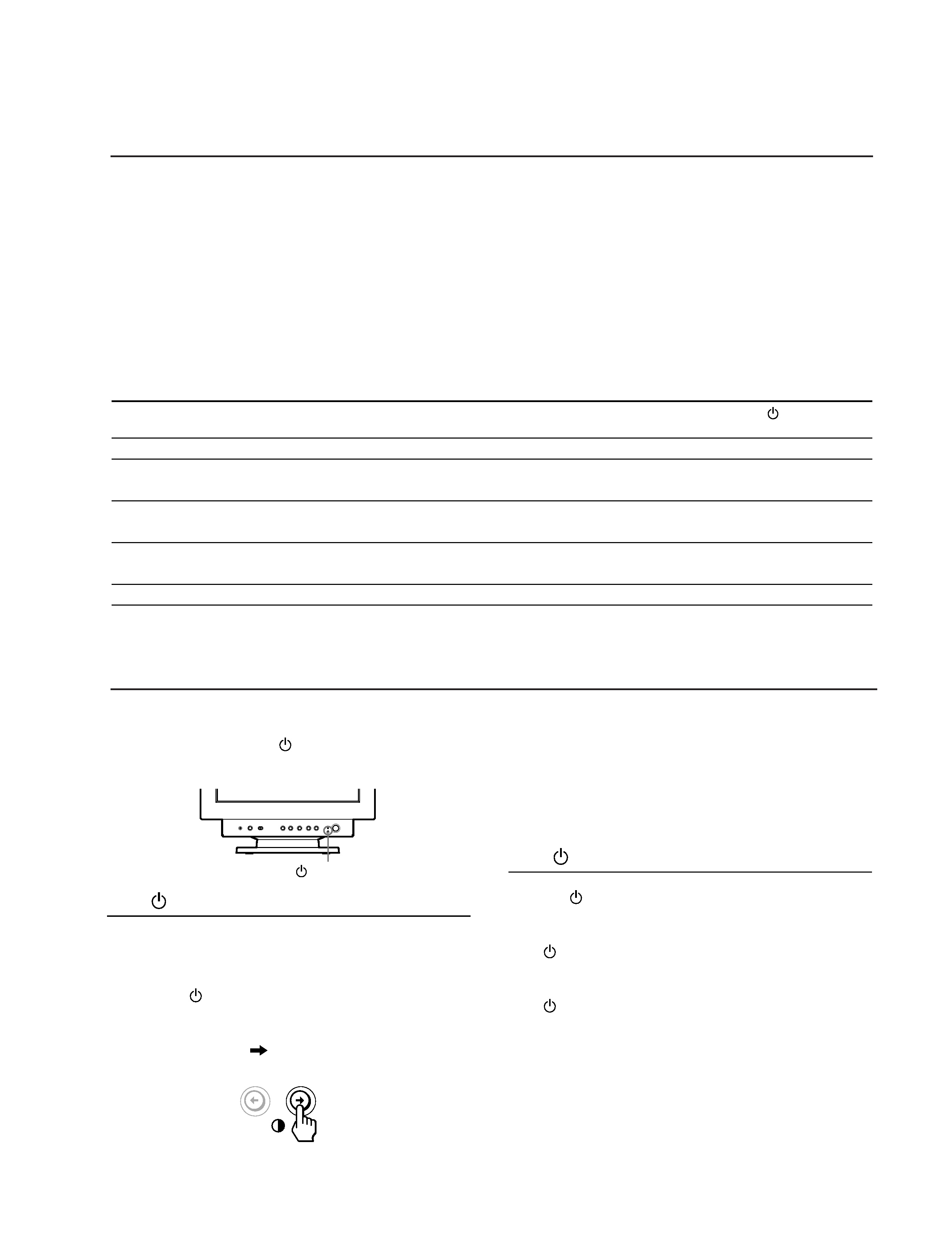
This monitor is equipped with a self-diagnosis function. If
there is a problem with your monitor or computer, the
screen will go blank and the
indicator will either light up
green or flash orange.
If the
indicator is green
1 Disconnect the video input cable or turn off the
connected computer.
2 Press the
button twice to turn the monitor off and
then on.
3 Press and hold the
button for 2 seconds before
the monitor enters power saving mode.
If all four color bars appear (white, red, green, blue), the
monitor is working properly. Reconnect the video input
cable and check the condition of your computer.
If the color bars do not appear, there is a potential monitor
failure. Inform the IBM HelpCenter of the monitor's
condition.
If the
indicator is flashing orange
Press the
button twice to turn the monitor off and
then on.
If the
indicator lights up green, the monitor is working
properly.
If the
indicator is still flashing, there is a potential
monitor failure. Inform the IBM HelpCenter of the monitor's
condition. Be sure to note the model name and serial
number of your monitor. Also note the make and model of
your computer and video board.
indicator
POWER SAVING FUNCTION
DIAGNOSIS
6551-T3N/6551-U3N
4
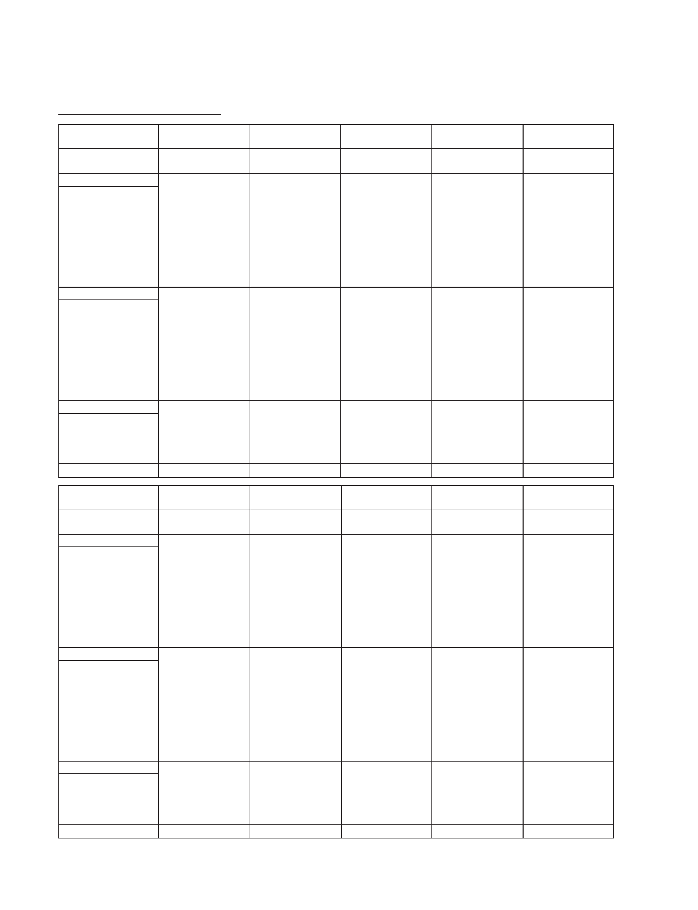
TIMING SPECIFICATION
MODE
TEST MODE
MODE AT PRODUCTION
MODE 1
MODE 2
MODE 3
MODE 4
MODE 5
RESOLUTION
640 X 480
640 X 480
800 X 600
800 X 600
1024 X 768
CLOCK
25.175 MHz
36.000 MHz
49.500 MHz
56.250 MHz
78.750 MHz
HORIZONTAL
H-FREQ
31.469 kHz
43.269 kHz
46.875 kHz
53.674 kHz
60.023 kHz
usec
usec
usec
usec
usec
H. TOTAL
31.778
23.111
21.333
18.631
16.660
H. BLK
6.356
5.333
5.172
4.409
3.657
H. FP
0.636
1.556
0.323
0.569
0.203
H. SYNC
3.813
1.556
1.616
1.138
1.219
H. BP
1.907
2.222
3.232
2.702
2.235
H. ACTIV
25.422
17.778
16.162
14.222
13.003
VERTICAL
V. FREQ(HZ)
59.940 Hz
85.008 Hz
75.000 Hz
85.061 Hz
75.029 Hz
lines
lines
lines
lines
lines
V. TOTAL
525
509
625
631
800
V. BLK
45
29
25
31
32
V. FP
10
1111
V. SYNC
2
3333
V. BP
33
25
21
27
28
V. ACTIV
480
480
600
600
768
SYNC
INT(G)
NO
NO
NO
NO
NO
EXT(H/V)/POLARITY
YES N/N
YES N/N
YES P/P
YES P/P
YES P/P
EXT(CS) /POLARITY
NO
NO
NO
NO
NO
INT/NON INT
NON INT
NON INT
NON INT
NON INT
NON INT
SIZE
352 X 264 mm
352 X 264 mm
352 X 264 mm
352 X 264 mm
352 X 264 mm
MODE
TEST MODE
MODE AT PRODUCTION
MODE 6
MODE 7
MODE 8
MODE 9
MODE 10
RESOLUTION
1024 X 768
1280 X 1024
1280 X 1024
1600 X 1200
1600 X 1200
CLOCK
94.500 MHz
135.000 MHz
157.500 MHz
202.500 MHz
229.500 MHz
HORIZONTAL
H-FREQ
68.677 kHz
79.976 kHz
91.146 kHz
93.750 kHz
106.250 kHz
usec
usec
usec
usec
usec
H. TOTAL
14.561
12.504
10.971
10.667
9.412
H. BLK
3.725
3.022
2.844
2.765
2.440
H. FP
0.508
0.119
0.406
0.316
0.279
H. SYNC
1.016
1.067
1.016
0.948
0.837
H. BP
2.201
1.837
1.422
1.501
1.325
H. ACTIV
10.836
9.481
8.127
7.901
6.972
VERTICAL
V. FREQ(HZ)
84.997 Hz
75.025 Hz
85.024 Hz
75.000 Hz
85.000 Hz
lines
lines
lines
lines
lines
V. TOTAL
808
1066
1072
1250
1250
V. BLK
40
42
48
50
50
V. FP
1
1111
V. SYNC
3
3333
V. BP
36
38
44
46
46
V. ACTIV
768
1024
1024
1200
1200
SYNC
INT(G)
NO
NO
NO
NO
NO
EXT(H/V)/POLARITY
YES P/P
YES P/P
YES P/P
YES P/P
YES P/P
EXT(CS) /POLARITY
NO
NO
NO
NO
NO
INT/NON INT
NON INT
NON INT
NON INT
NON INT
NON INT
SIZE
352 X 264 mm
330 X 264 mm
330 X 264 mm
352 X 264 mm
352 X 264 mm
99.04.26 VER.

6551-T3N/6551-U3N
5
TABLE OF CONTENTS
Section
Title
Page
1. GENERAL ................................................................. 1-1
2. DISASSEMBLY
2-1.
Cabinet Removal ................................................ 2-1
2-2.
Shield (EMI, Video),
Side Cover (L and R) Removal .......................... 2-1
2-3.
A Board Removal ............................................... 2-2
2-4.
Rear Shield Complete Assy,
D Board Removal ............................................... 2-2
2-5.
Service Position .................................................. 2-3
2-6.
H Board Removal ............................................... 2-3
2-7.
Picture Tube Removal ........................................ 2-4
2-8.
Harness Location ................................................ 2-5
3. SAFETY RELATED ADJUSTMENT ............. 3-1
4. ADJUSTMENTS ..................................................... 4-1
5. DIAGRAMS
5-1.
Block Diagrams .................................................. 5-1
5-2.
Frame Schematic Diagram ................................. 5-5
5-3.
Circuit Boards Location ..................................... 5-6
5-4.
Schematic Diagrams and Printed Wiring
Boards ................................................................. 5-7
(1)
Schematic Diagram of A Board ......................... 5-9
(2)
Schematic Diagrams of D (a,b,c) Board .... 5-11
(3)
Schematic Diagrams of N, H Boards ................. 5-19
5-5.
Semiconductors .................................................. 5-21
6. EXPLODED VIEWS
6-1.
Chassis ................................................................ 6-1
6-2.
Picture Tube ........................................................ 6-2
6-3.
Packing Materials ............................................... 6-3
7. ELECTRICAL PARTS LIST ............................ 7-1