R
RV
VD
D--6
60
09
90
0R
R
AUDIO/VIDEO RECEIVER
OPERATINGINSTRUCTIONS
ST TUNED AUTO
TAPE
M PRESET
Pro Logic
3 Stereo THEATER HALL
SLEEP
dB
kHz
MHz
MEM
ms
6 CH
DIRECT
DIGITAL
INPUTS
DSP MODE
STEREO
TUNING/PRESET
MODE
MASTER VOLUME
T0TALLY DISCRETE AMPLIFIER STAGE
TD A S
PHONES
BASS
TREBLE
CHANNEL LEVEL
VCR 2 INPUT
VIDEO
L
AUDIO
R
POWER
ON/OFF
SPEAKER
AUDIO
VIDEO
BAND
CHANNEL SELECTOR
TAPE MONITOR
ON/
OFF
TUNING/PRESET
INPUT SELECTOR
AUDIO/VIDEO RECEIVER RVD-6090R
REMOTE SENSOR
STANDBY
DIRECT
COAXIAL
OPTICAL
DIGITAL
DYNAMIC RANGE
CINEMA EQ
DIRECT
SPEAKER MODE
FM MODE
MEMO/ENTER
2
IIn
nttrro
od
du
uc
cttiio
on
n
C
Co
on
ng
grra
attu
ulla
attiio
on
ns
s o
on
n Y
Yo
ou
urr P
Pu
urrc
ch
ha
as
se
e!!
Yourn new high fidelity receiver is designed to deliver
maximum enjoyment and years of trouble free service.
Please take a few moments to read this manual
thoroughly. It will explain the features and operation of
your unit and help ensure a trouble free installation.
Please unpack your unit carefully. We recommend that
you save the carton and packing material. They will be
helpful if you ever need to move your unit and may be
required if you ever need to return it for service. Your unit
is designed to be placed in a horizontal position and it is
important to allow at least two inches of space behind
your unit for adequate ventilation and cabling
convenience.
To avoid damage, never place the unit near radiators, in
front of heating vents, in direct sunlight, or in excessively
humid or dusty locations. Connect your complementary
components as illustrated in the following section.
C
CA
AU
UT
TIIO
ON
N :: T
TO
O R
RE
ED
DU
UC
CE
E T
TH
HE
E R
RIIS
SK
K O
OF
F
E
EL
LE
EC
CT
TR
RIIC
C S
SH
HO
OC
CK
K,, D
DO
O N
NO
OT
T
R
RE
EM
MO
OV
VE
E C
CO
OV
VE
ER
R ((O
OR
R B
BA
AC
CK
K))..
N
NO
O U
US
SE
ER
R--S
SE
ER
RV
VIIC
CE
EA
AB
BL
LE
E P
PA
AR
RT
TS
S
IIN
NS
SIID
DE
E.. R
RE
EF
FE
ER
R S
SE
ER
RV
VIIC
CIIN
NG
G T
TO
O
Q
QU
UA
AL
LIIF
FIIE
ED
D S
SE
ER
RV
VIIC
CE
E P
PE
ER
RS
SO
ON
NN
NE
EL
L..
C
CA
AU
UT
TIIO
ON
N
RISK OF ELECTRIC SHOCK
DO NOT OPEN
This symbol is intended to alert the user to the
presence of uninsulated "dangerous voltage"
within the product's enclosure that may be of
sufficient magnitude to constitute a risk of
electric shock to persons.
This symbol is intended to alert the user to the
presence of important operating and
maintenance (servicing) instructions in the
literature accompanying the appliance.
To reduce the risk of fire or electric shock, do not expose
this appliance to rain or moisture.
C
Ca
au
uttiio
on
n :: D
Do
o n
no
ott b
bllo
oc
ck
k v
ve
en
nttiilla
attiio
on
n o
op
pe
en
niin
ng
gs
s o
orr s
stta
ac
ck
k
o
otth
he
err e
eq
qu
uiip
pm
me
en
ntt o
on
n tth
he
e tto
op
p..
F
FO
OR
R U
U..S
S..A
A..
N
No
otte
e tto
o C
CA
AT
TV
V S
Sy
ys
stte
em
m IIn
ns
stta
alllle
err:: This reminder is
provided to call the CATV system installer's attention
to Article 820-40 of the NEC that provides guidelines
for proper grounding and, in particular, specifies that
the cable ground shall be connected to the
grounding system of the building, as close to the
point of cable entry as practical.
F
FC
CC
C IIN
NF
FO
OR
RM
MA
AT
TIIO
ON
N
This equipment has been tested and found to
comply with the limits for a Class B digital device,
pursuant to Part 15 of the FCC Rules. These limits
are designed to provide reasonable protection
against harmful interference in a residential
installation. This equipment generates, uses and can
radiate radio frequency energy and, if not installed
and used in accordance with the instructions, may
cause harmful interference to radio communications.
However, there is no guarantee that interference will
not occur in a particular installation. If this equipment
does cause harmful interference to radio or
television reception, which can be determined by
turning the equipment off and on, the user is
encouraged to try to correct the interference by one
or more of the following measures:
Reorient or relocate the receiving antenna.
Increase the separation between the equipment
and receiver.
Connect the equipment into an outlet on a circuit
different from that to which the receiver is
connected.
Consult the dealer or an experienced radio/TV
technician for help.
C
CA
AU
UT
TIIO
ON
N:: Any changes or modifications in
construction of this device which are not expressly
approved by the party responsible for compliance
could void the user's authority to operate the
equipment.
W
WA
AR
RN
NIIN
NG
G
UNPACKING AND INSTALLATION
EE
NN
GG
LL
IISS
HH
F
FO
OR
R U
U..S
S..A
A.. A
AN
ND
D C
CA
AN
NA
AD
DA
A
..............................................................1
12
20
0 V
V
Units shipped to the U.S.A. and Canada are designed
for operation on 120 V AC only.
Observe all safety precautions with use of a polarized
AC plug.
However, some products may be supplied with a
nonpolarized plug.
C
CA
AU
UT
TIIO
ON
N :: To prevent electric shock, match wide
blade of plug to wide slot, fully insert.
F
FO
OR
R Y
YO
OU
UR
R S
SA
AF
FE
ET
TY
Y
F
FO
OR
R E
EU
UR
RO
OP
PE
E A
AN
ND
D A
AU
US
ST
TR
RA
AL
LIIA
A ..................2
23
30
0 V
V//2
24
40
0 V
V
Units shipped to Australia are designed for operation
on 240 V AC only.
To ensure safe operation, the three-pin plug supplied
must be inserted only into a standard three-pin
power point which is effectively earthed through the
normal household wiring. Extension cords used with
the equipment must be three-core and be correctly
wired to provide connection to earth.
Improper extension cords are a major cause of
fatalities. The fact that the equipment operates
satisfactorily does not imply that the power point is
earthed and that the installation is completely safe.
For your safety, if in any doubt about the effective
earthing of the power point, consult a qualified
electrician.
PAN-EUROPEAN UNIFIED VOLTAGE
All units are suitable for use on supplies 230-240 V
AC.
F
FO
OR
R Y
YO
OU
UR
R S
SA
AF
FE
ET
TY
Y
3
READ THIS BEFORE OPERATING YOUR UNIT
F
FO
OR
R O
OT
TH
HE
ER
R C
CO
OU
UN
NT
TR
RIIE
ES
S
..............................................1
11
10
0 V
V//2
22
20
0 V
V
Units shipped to countries other than the above
countries are equipped with an AC voltage selector
switch on the rear panel. Refer to the following
paragraph for the proper setting of this switch.
A
AC
C V
VO
OL
LT
TA
AG
GE
E S
SE
EL
LE
EC
CT
TIIO
ON
N
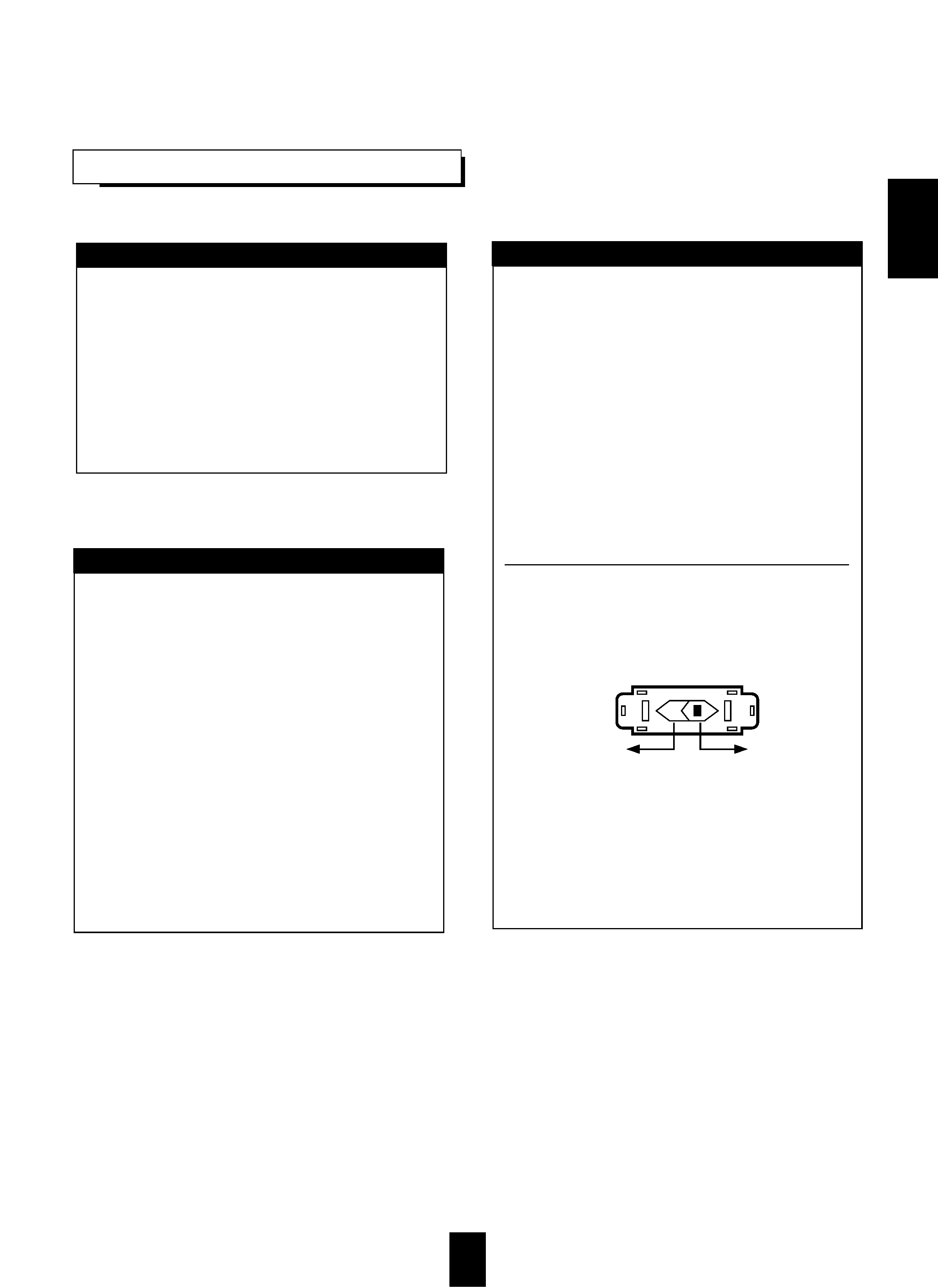
This unit operates on 110-220 V AC. The AC voltage
selector switch on the rear panel is set to the voltage
that prevails in the area to which the unit is shipped.
Before connecting the power cord to your AC outlet,
make sure that the setting position of this switch
matches your line voltage. If not, it must be set to
your voltage in accordance with the following
direction.
AC voltage selector switch
Move switch lever to match your line voltage with a
small screwdriver or other pointed tool.
F
FO
OR
R Y
YO
OU
UR
R S
SA
AF
FE
ET
TY
Y
AC 220 V
AC 110 V
EE
NN
GG
LL
IISS
HH

4
CONTENTS
Introduction
UNPACKING AND INSTALLATION ....................................................................................................... 2
READ THIS BEFORE OPERATING YOUR UNIT................................................................................... 3
System Connections........................................................................................................................................ 5
Front Panel Controls ...................................................................................................................................... 7
DIGI LINK III System Remote Controls ................................................................................................... 8
REMOTE CONTROL OPERATION RANGE............................................................................................ 9
LOADING BATTERIES.............................................................................................................................. 9
Operations
LISTENING TO A PROGRAM SOURCE................................................................................................ 10
SURROUND SOUND................................................................................................................................ 13
ENJOYING SURROUND SOUND........................................................................................................... 14
LISTENING TO RADIO BROADCASTS ................................................................................................ 18
RECORDING ............................................................................................................................................. 20
OTHER FUNCTIONS................................................................................................................................ 21
Troubleshooting Guide ................................................................................................................................22
Specifications.................................................................................................................................................. 23
EE
NN
GG
LL
IISS
HH
5
S
Sy
ys
stte
em
m C
Co
on
nn
ne
ec
cttiio
on
ns
s
CD
PLAY
ANTENNA
AC INPUT
120V~60Hz
2.1A
MODEL NO. RVD-6090R
AUDIO/VIDEO RECEIVER
FRONT
SWITCHED
120V~60Hz
100W 1A MAX
AC OUTLET
This device complies with Part 15 of the FCC Rules.
Operation is subject to the following two conditions:
(1)This device may not cause harmful interference, and
(2)this device must accept any interference received,
including interference that may cause undesired operation.
SER. NO
C
E85649
29Z3
LISTED
AUDIO EQUIPMENT
R
R
W ARNING:"SHOCK HAZARD-DO NOT OPEN"
A VIS:"RISQUE DE CHOC-ELECTRIQUE-NE P AS
OUVRIR"
CAUTION
RISK OF ELECTRIC SHOCK
DO NOT OPEN
MADE IN KOREA
DESIGNED IN USA
Manufactured under license from Dolby Laboratories. "Dolby",
"PRO LOGIC" and the double-D symbol are trademarks of Dolby
Laboratories. Confidential Unpublished Works. ©1992-1997 Dolby
Laboratories, Inc. All rights reserved.
SUB
WOOFER
SUB
WOOFER
PRE
OUT
CENTER
REAR
LR
FRONT
REAR
CENTER
6-CH
DIRECT
INPUT
REC
AUX
DVD/
TV
IN
OUT
VIDEO
MON.
OUT
VIDEO
L
R
VCR1
TAPE MON.
DIGI-LINK
CENTER SPEAKER(8)
FRONT
SPEAKERS
(8)
REAR
SPEAKERS
(8)
L
L
R
R
DIGITAL
INPUTS
COAXIAL
AC-3/PCM
OPTICAL
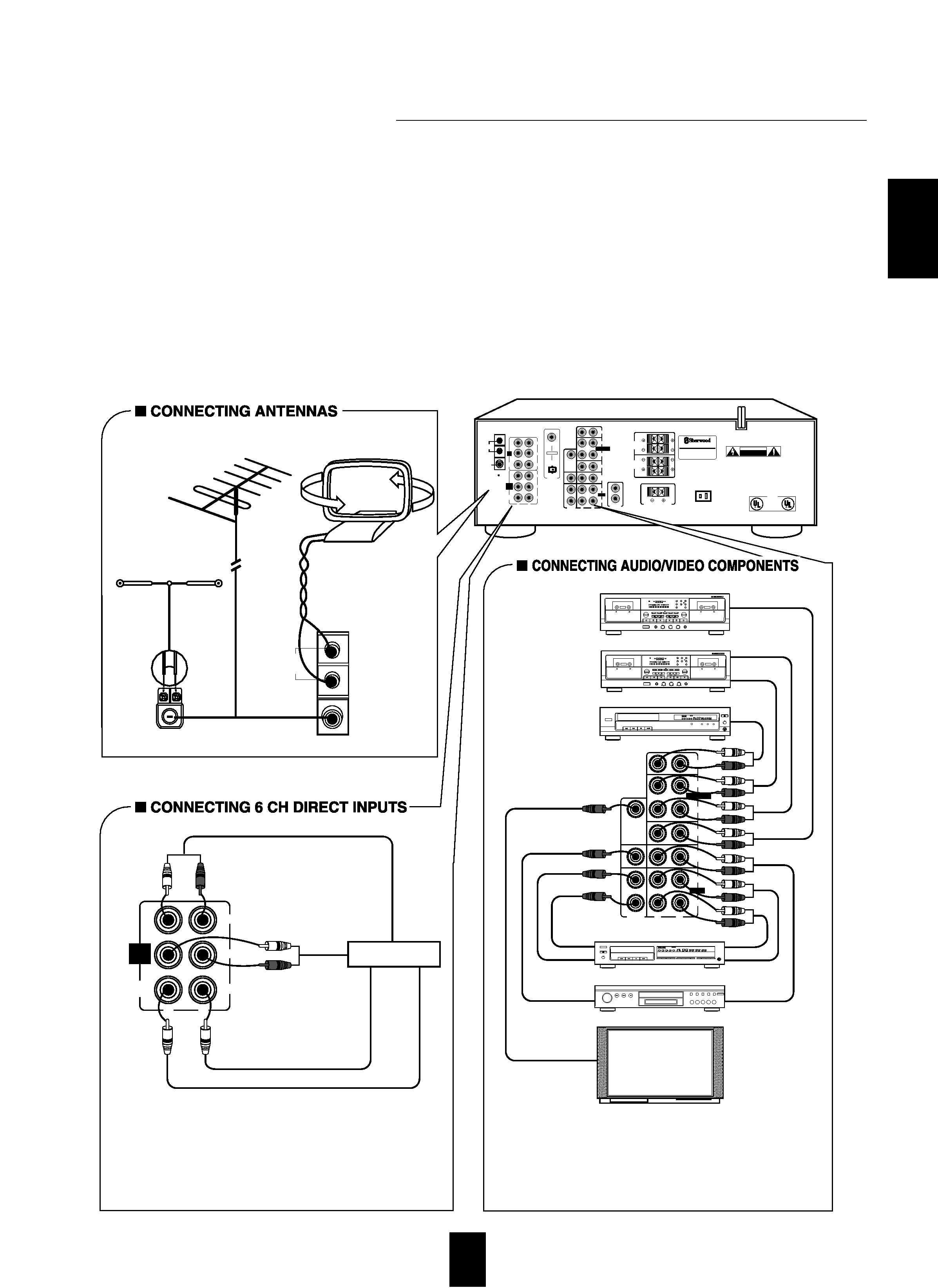
q
Use these jacks to connect the corresponding analog
outputs of 6 CH decoder or DVD player with 6 CH
output for Dolby Digital or DTS, etc.
(For details, see the operator's manual of the component
to be connected.)
6 CH decoder
REAR
CH OUT
CENTER CH OUT
FRONT CH OUT
SUBWOOFER CH OUT
SUB
WOOFER
LR
FRONT
REAR
CENTER
6-CH
DIRECT
INPUT
Tape deck or additional audio component
BC
NORM
HIGH
SYN
MPX
MIN
SEC
RELAY
REC
P
CD
M
REC
L
R
dB
-00
-20
-10
-6
-3
0
+3
+6
DIGI-LINK STEREO DOUBLE CASSETTE DECK DD-5080C
AUTO REVERSE
PLAY/AUTO TAPE SELECTOR
RECORD & PLAY/AUTO TAPE SELECTOR
HX-PRO
AUTO REVERSE
RESET
A/B
MODE
R PLAY
DUBBING
O/O
CD SUN REC
HIGH
NORMAL
AMS
AMS
EJECT
REC BALAMCE
REC LEVEL
PHONES
POWER
MIC MIX
MIC
SOURCE
LR
0
10
MIC
REVERSE
T SIZE
MEMORY
B/C/OFF
COUNTER
BA
CD player
POWER
REMOTE SENSOR
PROGRAM/REVIEW RANDOM
REPEAT
OPEN/CLOSE
PHONES LEVEL
PHONES
MIN
MAX
ON/OFF
MULTIPLE COMPACT DISC PLAYER CDC-5080R
1
2
3
4
5
GRAPHICS
PEAK
DELETE
EDIT
SCENE TRACK
INDEX STEP
AB
V-CD
PBC REVERT PROG
AUTO
RANDOM REPEAT ALL 1 DISC S
12
3
45
6
78
9
10 11 12
13 14 15
MPX INTRO
A< >B
POWER
OPEN/CLOSE
PHONES LEVEL
PHONES
MIN
MAX
ON/OFF
MULTIPLE COMPACT DISC PLAYER CDC-5080R
1
2
3
4
5
GRAPHICS
PEAK
DELETE
EDIT
SCENE TRACK
INDEX
STEP
AB
V-CD
PBC
REVERT
PROG
AUTO
RANDOM
REPEAT
ALL
1 DISC S
12
3
45
6
78
9
10
11 12
13
14 15
MPX
INTRO
A< >B
Video deck 1
POWER
ON/OFF
MULTIPLE COMPACT DISC PLAYER CDC-5080R
DVD player or additional video component
Monitor TV
q
The TAPE MONITOR PLAY/REC jacks may also be
connected to the LINE OUT/IN jacks of an optional graphic
equalizer.
q
The DVD/TV jacks may also be connected to an additional
video component such as a cable TV tuner or a video deck.
BC
NORM
HIGH
SYN
MPX
MIN
SEC
RELAY
REC
P
CD
M
REC
L
R
dB
-00
-20
-10
-6
-3
0
+3
+6
DIGI-LINK STEREO DOUBLE CASSETTE DECK DD-5080C
AUTO REVERSE
PLAY/AUTO TAPE SELECTOR
RECORD & PLAY/AUTO TAPE SELECTOR
HX-PRO
AUTO REVERSE
RESET
A/B
MODE
R PLAY
DUBBING
O/O
CD SUN REC
HIGH
NORMAL
AMS
AMS
EJECT
REC BALAMCE
REC LEVEL
PHONES
POWER
MIC MIX
MIC
SOURCE
LR
0
10
MIC
REVERSE
T SIZE
MEMORY
B/C/OFF
COUNTER
BA
*Tape deck or graphic equalizer
CD
REC
PLAY
AUX
DVD/
TV
IN
OUT
VIDEO
MON.
OUT
VIDEO
L
R
VCR1
VIDEO IN
OUT
OUT
PLAY(OUT)
PLAY(OUT)
REC(IN)
REC(IN)
PLAY(LINE OUT)
PLAY(LINE OUT)
REC(LINE IN)
TAPE MON.
FM
75
AM
LOOP
AM loop antenna
FM
FM
(INDOOR ANTENNA)
(OUTDOOR ANTENNA)
SUPPLIED ADAPTOR
300 ohm
feeder
AM
LOOP
FM
75
Do not plug the AC input cord into the wall AC outlet until all connections are completed.
Be sure to connect the white RCA cord to the L(left) and the red RCA cord to the R(right) jacks when making audio
connections.
Change the position of the FM indoor antenna until you get the best reception of your favorite FM stations.
A 75 outdoor FM antenna may be used to further improve the reception.
Disconnect the indoor antenna before replacing it with the outdoor one.
Place the AM loop antenna as far as possible from the receiver, TV set, speaker wires and the AC input cord.
Point it in the direction that offers the best reception.
If the reception is poor with the AM loop antenna, an AM outdoor antenna can be used in place of the AM loop antenna.
Make connections firmly and correctly. If not, it can cause loss of sound, noise or damage to the receiver.
If the electricity fails or the AC input cord is left unplugged for about 2 weeks, the memorized contents will be cleared.
Should this happen, memorize them again.
EE
NN
GG
LL
IISS
HH