
RD-8500
OPERATING INSTRUCTIONS
BEDIENUNGSANLEITUNG
ENGLISH
2
Introduction
READ THIS BEFORE OPERATING YOUR UNIT
This symbol is intended to alert the user to the
presence of uninsulated "dangerous voltage"
within the product's enclosure that may be of
sufficient magnitude to constitute a risk of
electric shock to persons.
This symbol is intended to alert the user to the
presence of important operating and
maintenance (servicing) instructions in the
literature accompanying the appliance.
Caution regarding placement
To maintain proper ventilation, be sure to leave a space around the unit (from the largest
outer dimensions including projections)
equal to, or greater than, shown below.
Left and right panels: 5 cm
Rear panel: 5 cm
Top panel: 20 cm
Do not block ventilation openings or stack other equipment on the top.
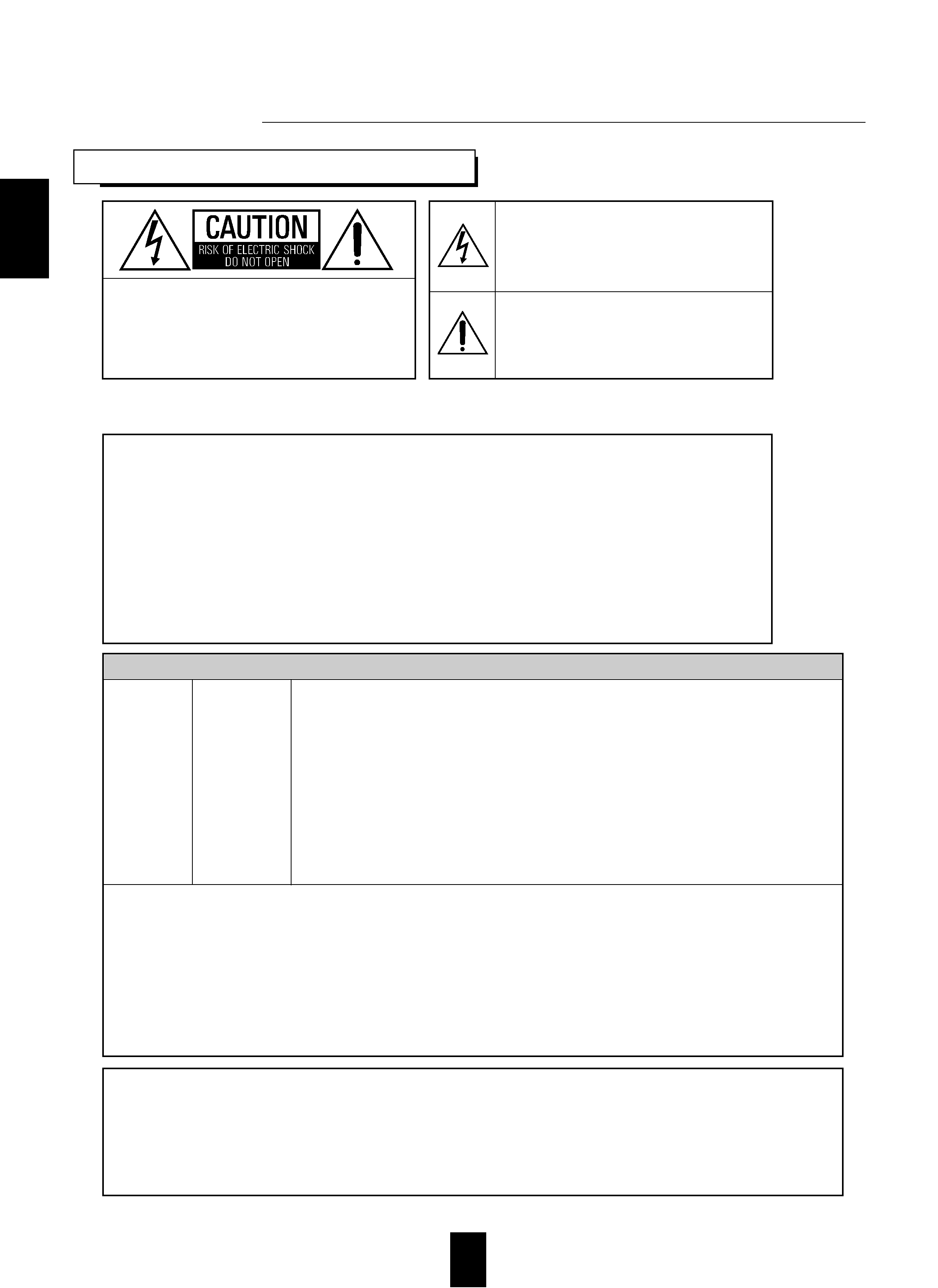
: TO REDUCE THE RISK OF
ELECTRIC SHOCK, DO NOT
REMOVE COVER (OR BACK). NO
USER-SERVICEABLE PARTS
INSIDE. REFER SERVICING TO
QUALIFIED SERVICE PERSONNEL.
CAUTION
: TO REDUCE THE RISK OF FIRE OR ELECTRIC SHOCK,
DO NOT EXPOSE THIS APPLIANCE TO RAIN OR MOISTURE.
WARNING
To ensure safe operation, the three-pin plug supplied must be inserted only into a
standard three-pin power point which is effectively earthed through the normal
household wiring. Extension cords used with the equipment must be three-core and
be correctly wired to provide connection to earth.
Improper extension cords are a major cause of fatalities. The fact that the
equipment operates satisfactorily does not imply that the power point is earthed
and that the installation is completely safe. For your safety, if in any doubt about the
effective earthing of the power point, consult a qualified electrician.
PAN-EUROPEAN UNIFIED VOLTAGE
All units are suitable for use on supplies 220-240 V AC.
FOR YOUR SAFETY
EUROPE
AUSTRALIA
220 V
-
240 V
· Avoid high temperatures. Allow for sufficient heat dispersion when installed on a rack.
· Keep the set free from moisture, water, and dust.
· Do not let foreign objects in the set.
· Handle the power cord carefully. Hold the plug when unplugging the cord.
· Unplug the power cord when not using the set for long periods of time.
· Do not obstruct the ventilation holes.
· Do not let insecticides, benzene, and thinner come in contact wth the set.
· Never disassemble or modify the set in any way.
CAUTION
· The ventilation should not be impeded by covering the ventilation openings with items, such
as newspapers, table-cloths, curtains, etc.
· No naked flame sources, such as lighted candles, should be placed on the apparatus.
· Please be care the environmental aspects of battery disposal.
· The apparatus shall not be exposed to dripping or splashing for use.
· No objects filled with liquids, such as vases, shall be placed on the apparatus.

3
CONTENTS
Introduction
· READ THIS BEFORE OPERATING YOUR UNIT........................................................................................................ 2
System Connections ........................................................................................................................................................... 4
Front Panel Controls ....................................................................................................................................................... 10
Universal Remote Controls............................................................................................................................................ 12
· OPERATING COMPONENTS WITH REMOTE CONTROL......................................................................................14
· REMOTE CONTROL OPERATION RANGE .............................................................................................................. 14
· LOADING BATTERIES ................................................................................................................................................ 14
· USING FUNCTIONS OF REMOTE CONTROL .......................................................................................................... 15
Operations
· LISTENING TO A PROGRAM SOURCE..................................................................................................................... 18
· SURROUND SOUND .................................................................................................................................................... 21
· ENJOYING SURROUND SOUND................................................................................................................................ 26
· LISTENING TO RADIO BROADCASTS ..................................................................................................................... 31
· LISTENING TO RDS BROADCASTS(FM only) ......................................................................................................... 33
· RECORDING .................................................................................................................................................................. 36
· DIGITAL AUDIO RECORDING WITH MD RECORDER.......................................................................................... 37
· OTHER FUNCTIONS .................................................................................................................................................... 38
Using the OSD
· CURRENT STATUS DISPLAY..................................................................................................................................... 39
· MENU SCREEN ............................................................................................................................................................. 39
Troubleshooting Guide ................................................................................................................................................... 42
Specifications ..................................................................................................................................................................... 43
Setup Code Table ............................................................................................................................................................. 44
ENGLISH
4
System Connections
· Do not plug the AC input cord into the wall AC outlet until all connections are completed.
· Be sure to observe the color coding when connecting audio and video cords.
· Make connections firmly and correctly. If not, it can cause loss of sound, noise or damage to the receiver.
· If the electricity fails or the AC input cord is left unplugged for more than 2 weeks, the memorized contents will be cleared.
Should this happen, memorize them again.
AC OUTLET
FRONT
SPEAKERS
(6
)
SURROUND
SPEAKERS
(6
)
CENTER
SPEAKER
(6
)
SURROUND
BACK
(6
)
OPT 1
OPT 2
COAX
1
COAX
2
DIGITAL
AM
LOOP
FM
75
ANTENNA
SURROUND
BACK
CENTER
FRONT
SURROUND
PLAY
REC
PLAY
REC
PLAY
VIDEO 1
VIDEO 2
7-CH DIRECT INPUT
SUB
WOOFER
PRE OUT
SUB WOOFER
VIDEO 1
VIDEO 2
MONITOR
VIDEO
OUT
VIDEO
IN
VIDEO 1
CD
AUX
DIGI-LINK
OUT
IN
TAPE
OPTICAL
VIDEO 1 VIDEO 2
S-VIDEO
COMPONENT
IN
OUT
VIDEO 1
MONITOR
VIDEO 1
VIDEO 2
IN
IN
OUT
MONITOR
1. CONNECTING ANTENNAs
AM
LOOP
ANTENNA
FM
75
FM Indoor Antenna
FM Outdoor Antenna
AM
LOOP
ANTENNA
FM
75
· Change the position of the FM indoor antenna until you
get the best reception of your favorite FM stations.
AM Loop Antenna
AM Outdoor Antenna
AM
LOOP
ANTENNA
FM
75
· Place the AM loop antenna as far as possible
from the receiver, TV set, speaker cords and the
AC input cord and set it to a direction for the
best reception.
· If the reception is poor with the AM loop anten-
na, an AM outdoor antenna can be used in
place of the AM loop antenna.
· A 75
outdoor FM antenna may be used to further
improve the reception. Disconnect the indoor
antenna before replacing it with the outdoor one.
ENGLISH
5
PLAY
REC
CD
AUX
TAPE
TAPE Tape deck, MD recorder, etc.
AUX other audio component
AUDIO
OUT
R
L
L
R
L
R
CD player
AUDIO
OUT
R
L
AUDIO
OUT
AUDIO
IN
SURROUND
BACK
CENTER
FRONT
SURROUND
SUB
WOOFER
7-CH DIRECT INPUT
SURROUND
SUBWOOFER
FRONT
CENTER
7 CH DIRECT OUTPUT
Decoder with 6 or 7
channel outputs
RR
L
L
BACK
2. CONNECTING 7 CH DIRECT INPUTS
· Use these jacks to connect the corresponding analog outputs of a DVD player or external decoder, etc. that has 6 or 7
channel outputs.
· In case of 6 channel outputs, do not connect this SURROUND BACK input to your audio component.
(For details, refer to the operating instructions of the component to be connected.)
3. CONNECTING AUDIO COMPONENTS
· The AUX jacks may be connected to an additional audio component such as a CD player, a tape deck, etc.
ENGLISH