2
Introduction
Congratulations on Your Purchase!
Your new high fidelity receiver is designed to deliver
maximum enjoyment and years of trouble free service.
Please take a few moments to read this manual
thoroughly. It will explain the features and operation of
your unit and help ensure a trouble free installation.
Please unpack your unit carefully. We recommend that
you save the carton and packing material. They will be
helpful if you ever need to move your unit and may be
required if you ever need to return it for service. Your unit
is designed to be placed in a horizontal position and it is
important to allow at least two inches of space behind
your unit for adequate ventilation and cabling
convenience.
To avoid damage, never place the unit near radiators, in
front of heating vents, in direct sunlight, or in excessively
humid or dusty locations. Connect your complementary
components as illustrated in the following section.
CAUTION : TO REDUCE THE RISK OF
ELECTRIC SHOCK, DO NOT
REMOVE COVER (OR BACK).
NO USER-SERVICEABLE PARTS
INSIDE. REFER SERVICING TO
QUALIFIED SERVICE PERSONNEL.
CAUTION
RISK OF ELECTRIC SHOCK
DO NOT OPEN
This symbol is intended to alert the user to the
presence of uninsulated "dangerous voltage"
within the product's enclosure that may be of
sufficient magnitude to constitute a risk of
electric shock to persons.
This symbol is intended to alert the user to the
presence of important operating and
maintenance (servicing) instructions in the
literature accompanying the appliance.
To reduce the risk of fire or electric shock, do not expose
this appliance to rain or moisture.
Caution : Do not block ventilation openings or stack
other equipment on the top.
FOR U.S.A
Note to CATV System Installer: This reminder is
provided to call the CATV system installer's attention
to Article 820-40 of the NEC that provides guidelines
for proper grounding and, in particular, specifies that
the cable ground shall be connected to the
grounding system of the building, as close to the
point of cable entry as practical.
FCC INFORMATION
This equipment has been tested and found to
comply with the limits for a Class B digital device,
pursuant to Part 15 of the FCC Rules. These limits
are designed to provide reasonable protection
against harmful interference in a residential
installation. This equipment generates, uses and can
radiate radio frequency energy and, if not installed
and used in accordance with the instructions, may
cause harmful interference to radio communications.
However, there is no guarantee that interference will
not occur in a particular installation. If this equipment
does cause harmful interference to radio or
television reception, which can be determined by
turning the equipment off and on, the user is
encouraged to try to correct the interference by one
or more of the following measures:
· Reorient or relocate the receiving antenna.
· Increase the separation between the equipment
and receiver.
· Connect the equipment into an outlet on a circuit
different from that to which the receiver is
connected.
· Consult the dealer or an experienced radio/TV
technician for help.
CAUTION: Any changes or modifications in
construction of this device which are not expressly
approved by the party responsible for compliance
could void the user's authority to operate the
equipment.
WARNING
ENGLISH
UNPACKING
AND
Caution regarding placement
(Except for U.S.A and Canada)
To maintain proper ventilation, be sure
to leave a space around the unit (from
the largest outer dimensions including projections)
equal to, or greater than, shown below.
Left and right panels: 5 cm
Rear panel: 10 cm
Top panel: 20 cm
FOR U.S.A AND CANADA ..............................120 V
Units shipped to the U.S.A and Canada are designed
for operation on 120 V AC only.
Safety precaution with use of a polarized AC plug.
However, some products may be supplied with a
nonpolarized plug.
CAUTION : To prevent electric shock, match wide
blade of plug to wide slot, fully insert.
FOR YOUR SAFETY
FOR EUROPE AND AUSTRALIA .........230 V/240 V
Units shipped to Australia are designed for operation
on 240 V AC only.
To ensure safe operation, the three-pin plug supplied
must be inserted only into a standard three-pin
power point which is effectively earthed through the
normal household wiring. Extension cords used with
the equipment must be three-core and be correctly
wired to provide connection to earth.
Improper extension cords are a major cause of
fatalities. The fact that the equipment operates
satisfactorily does not imply that the power point is
earthed and that the installation is completely safe.
For your safety, if in any doubt about the effective
earthing of the power point, consult a qualified
electrician.
PAN-EUROPEAN UNIFIED VOLTAGE
All units are suitable for use on supplies 230~240 V
AC.
FOR YOUR SAFETY
3
ENGLISH
READ THIS BEFORE OPERATING
FOR OTHER COUNTRIES ................... 115 V/230 V
Units shipped to countries other than the above
countries are equipped with an AC voltage selector
switch on the rear panel. Refer to the following
paragraph for the proper setting of this switch.
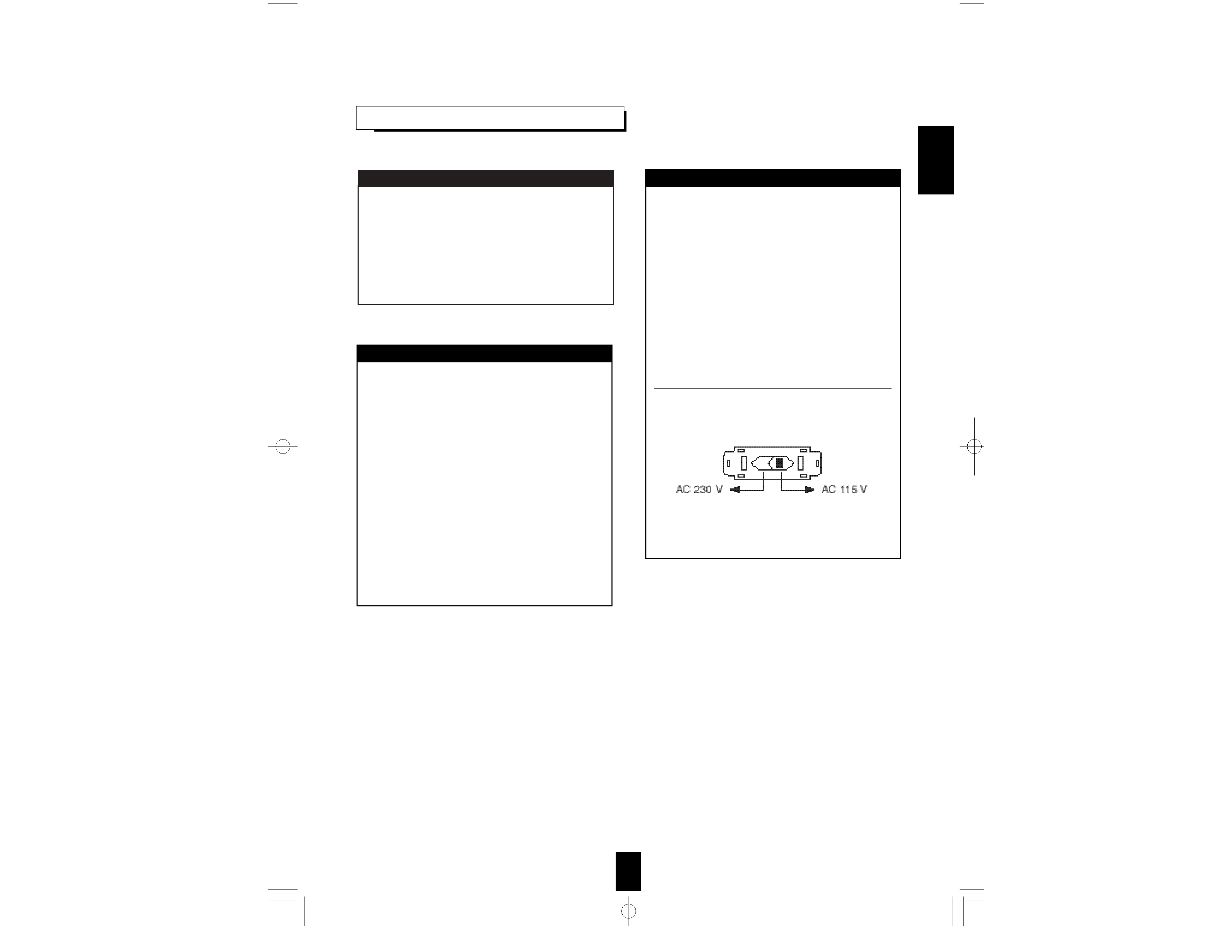
AC VOLTAGE SELECTION
This unit operates on 115/230 V AC. The AC voltage
selector switch on the rear panel is set to the voltage
that prevails in the area to which the unit is shipped.
Before connecting the power cord to your AC outlet,
make sure that the setting position of this switch
matches your line voltage. If not, it must be set to
your voltage in accordance with the following
direction.
AC voltage selector switch
Move switch lever to match your line voltage with a
small screwdriver or other pointed tool.
FOR YOUR SAFETY
4
CONTENTS
Introduction
· UNPACKING AND INSTALLATION......................................................................................................... 2
· READ THIS BEFORE OPERATING YOUR UNIT .................................................................................... 3
System Connections........................................................................................................................................ 5
Front Panel Controls ...................................................................................................................................... 7
Remote Controls.............................................................................................................................................. 8
· REMOTE CONTROL OPERATION RANGE ............................................................................................. 9
· LOADING BATTERIES ............................................................................................................................... 9
Operations
· LISTENING TO A PROGRAM SOURCE .................................................................................................10
· SURROUND SOUND ................................................................................................................................. 13
· ENJOYING SURROUND SOUND ............................................................................................................ 15
· LISTENING TO RADIO BROADCASTS.................................................................................................. 20
· RECORDING............................................................................................................................................... 22
· OTHER FUNCTIONS ................................................................................................................................. 23
Troubleshooting Guide ................................................................................................................................24
Specifications.................................................................................................................................................. 25
ENGLISH
5
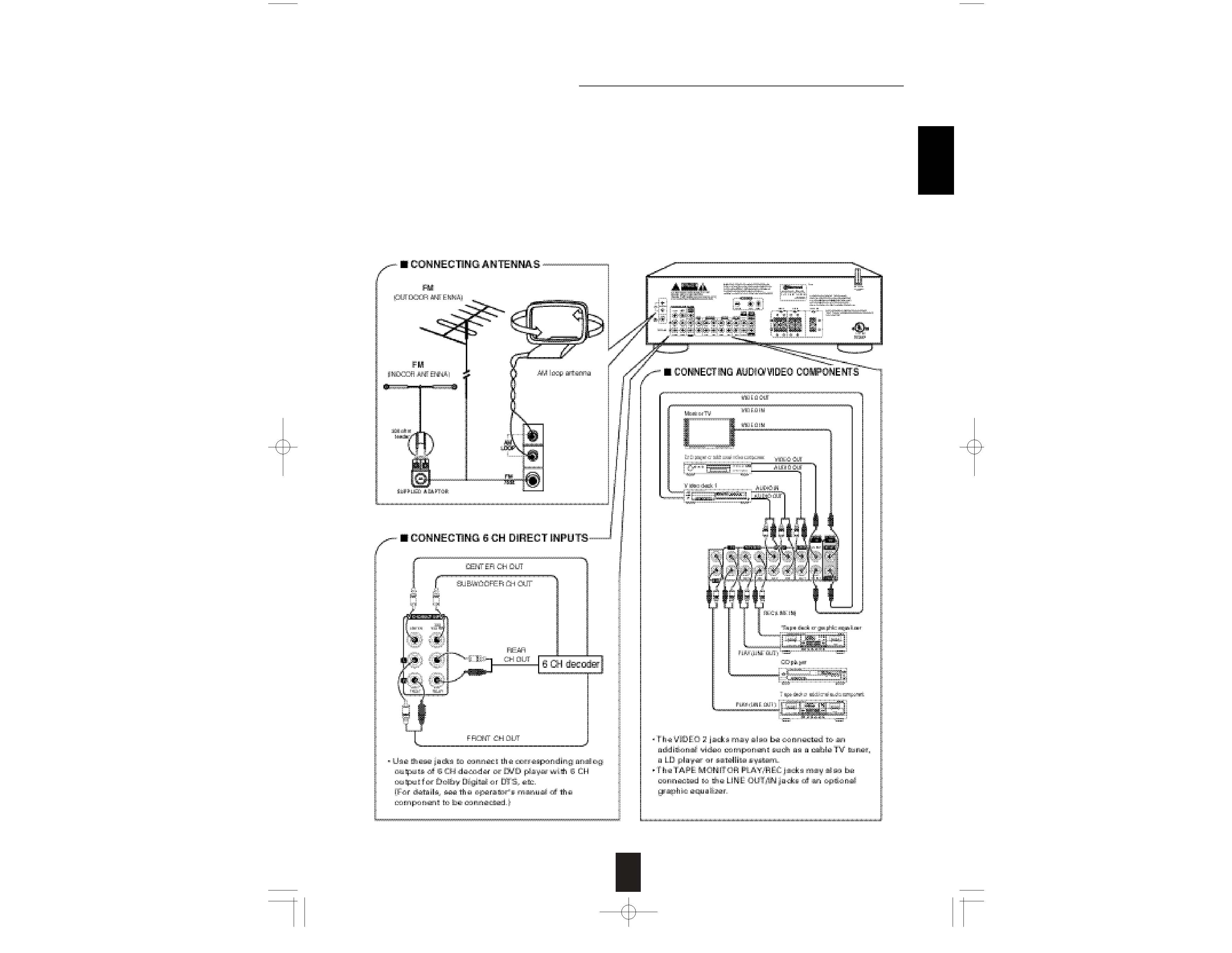
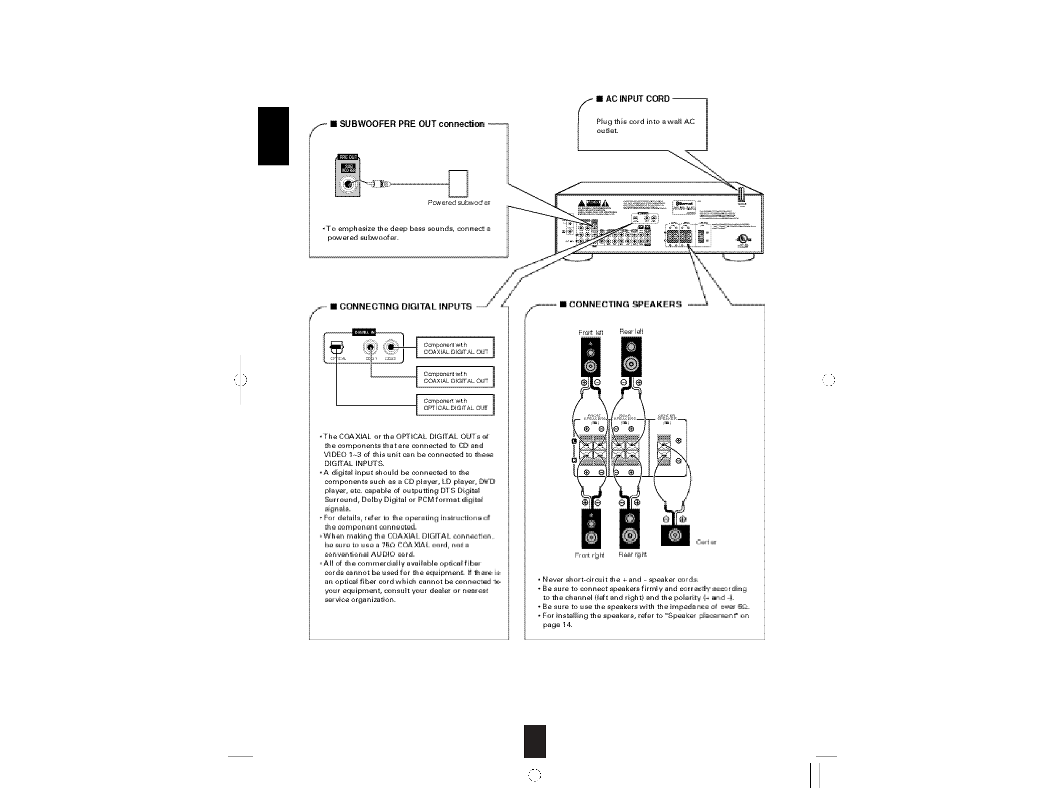
System Connections
· Do not plug the AC input cord into the wall AC outlet until all connections are completed.
· Be sure to observe the color coding when connecting audio and video cords.
· Change the position of the FM indoor antenna until you get the best reception of your favorite FM stations.
· A 75 outdoor FM antenna may be used to further improve the reception.
Disconnect the indoor antenna before replacing it with the outdoor one.
· Place the AM loop antenna as far as possible from the receiver, TV set, speaker cords and the AC input cord and set it to a
direction for the best reception.
· If the reception is poor with the AM loop antenna, an AM outdoor antenna can be used in place of the AM loop antenna.
· Make connections firmly and correctly. If not, it can cause loss of sound, noise or damage to the receiver.
· If the electricity fails or the AC input cord is left unplugged for more than 2 weeks, the memorized contents will be cleared.
Should this happen, memorize them again.
ENGLISH
6
ENGLISH