RDS RT TIMER12 ST TUNED AUTO VCR12V-CD TAPE 2 M PRESET
EON TP TA PTY
Pro Logic
3 Stereo THEATER HALL
SLEEP
dB
kHz
MHz
MEM
ms
R-125
AUDIO/VIDEO RECEIVER
OPERATINGINSTRUCTIONS
READ THIS BEFORE OPERATING YOUR UNIT
FOR U.S.A. AND CANADA ...............................................120V
Units shipped to the U.S.A. and Canada are designed for
operation on 120 V AC only.
Safety precaution with use of a polarized AC plug.
However, some products may be supplied with a nonpolarized
plug.
CAUTION : To prevent electric shock, match wide blade of plug
to wide slot, fully insert.
ATTENTION : Pour eviter les choc electriques, introduire la lame
la plug large de la borne correspondante de la prise et poussre
jusqu'au fond.
INTRODUCTION
UNPACKING AND INSTALLATION
Congratulations on Your Purchase!
Your new high fidelity Receiver is designed to deliver maximum
enjoyrnent and years of trouble free service.
Please take a few moments to read this manual thoroughly. It will
explain the features and operation of your unit and help a trouble free
installation.
Please unpack your unit carefully. We recommend that you save the
carton and packing material. They will be helpful if you ever need to
move your unit and may be required if you ever need to return it for
service. Your unit is designed to be placed in a horizontal position and it
is important to allow at least two inches of space behind your unit for
adequate ventilation and cabling convenience.
To avoid damage, never place the unit near radiators, in front of heating
vents, in direct sunlight, or in excessively humid or dusty locations.
Connect your complimentary components as illustrated in the following
section.
2
CAUTION : TO REDUCE THE RISK OF
ELECTRIC SHOCK, DO NOT
REMOVE COVER (OR BACK).
NO USER-SERVICEABLE PARTS
INSIDE. REFER SERVICING TO
QUALIFIED SERVICE PERSONNEL.
CAUTION
RISK OF ELECTRIC SHOCK
DO NOT OPEN
This symbol is intended to alert the user to the
presence of uninsulated "dangerous voltage" within
the product's enclosure that may be of sufficient
magnitude to constitute a risk of electric shock to
persons.
This symbol is intended to alert the user to the
presence of important operating and maintenance
(servicing) instructions in the literature
accompanying the appliance.
To reduce the risk of fire or electric shock, do not expose this appliance
to rain or moisture.
Caution : Do not block ventilation openings or stack other
equipment on the top.
FOR U.S.A.
Note to CATV System Installer: This reminder is provided to call the
CATV system installer's attention to Article 820-40 of the NEC that
provides guidelines for proper grounding and, in particular, specifies that
the cable ground shall be connected to the grounding system of the
building, as close to the point of cable entry as practical.
FCC INFORMATION
This equipment has been tested and found to comply with the limits for a
Class B digital device, pursuant to Part 15 of the FCC Rules. These
limits are designed to provide reasonable protection against harmful
interference in a residential installation. This equipment generates, uses
and can radiate radio frequency energy and, if not installed and used in
accordance with the instructions, may cause harmful interference to
radio communications. However, there is no guarantee that interference
will not occur in a particular installation. If this equipment does cause
harmful interference to radio or television reception, which can be
determined by turning the equipment off and on, the user is encouraged
to try to correct the interference by one or more of the following
measures:
Reorient or relocate the receiving antenna.
Increase the separation between the equipment and receiver.
Connect the equipment into an outlet on a circuit different from that to
which the receiver is connected.
Consult the dealer or an experienced radio TV technician for help.
CAUTION: Any changes or modifications in construction of this device
which are not expressly approved by the party responsible for
compliance could void the user's authority to operate the equipment.
FOR YOUR SAFETY
FOR AUSTRALIA AND EUROPE .......... 220V/230 V/240 V
Units shipped to Australia are designed for operation on 240 V
AC only.
To ensure safe operation the three-pin plug supplied must be
inserted only into a standard three-pin power point which is
effectively earthed through the normal household wiring.
Extension cords used with the equipment must be three-core
and be correctly wired to provide connection to earth.
Improper extension cords are a major cause of fatalities. The
fact that the equipment operates satisfactorily does not imply
that the power point is earthed and that the installation is
completely safe. For your safety, if in any doubt about the
effective earthing of the power point, consult a qualified
electrician.
PAN-EUROPEAN UNIFIED VOLTAGE
All units are suitable for use on supplies 220-240V AC.
FOR YOUR SAFETY
FOR OTHER COUNTRIES ............................... 120V/220 V
Units shipped to countries other than the above countries are
equipped with an AC voltage selector switch on the rear panel.
Refer to the following paragraph for the proper setting of this
switch.
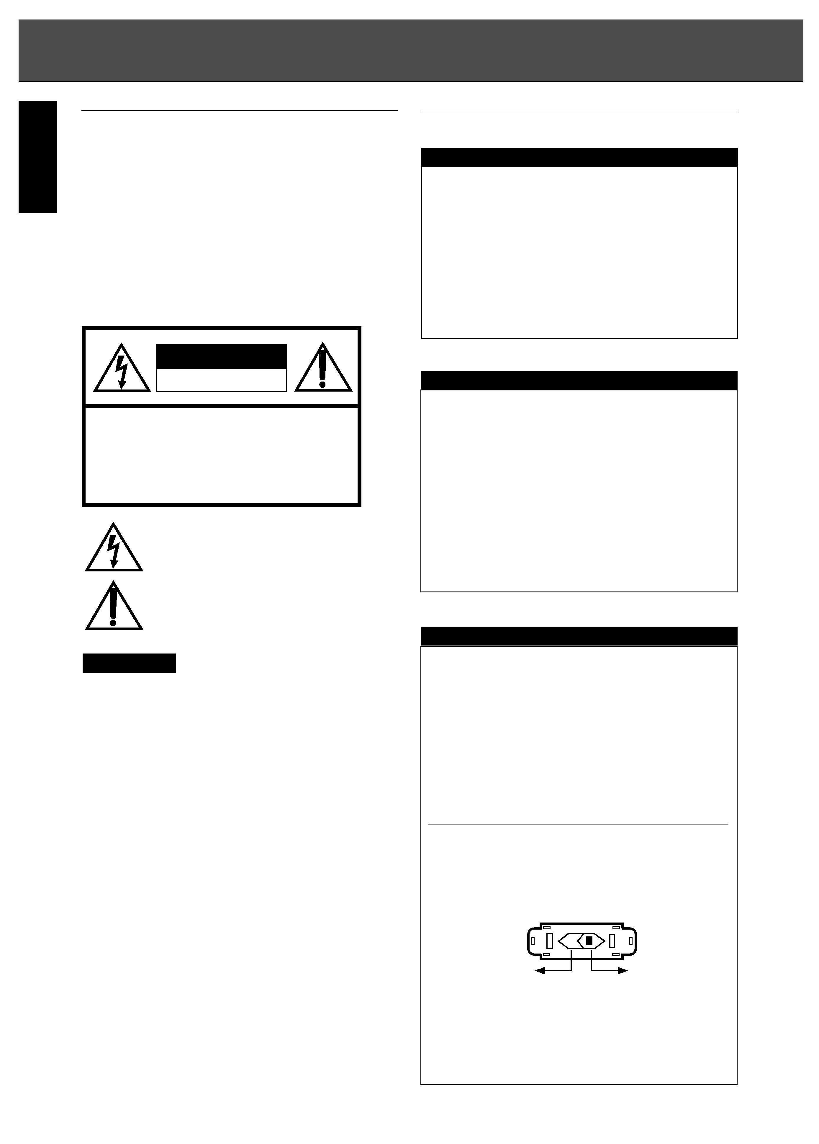
AC VOLTAGE SELECTION
This unit operates on 110-220 V AC. The AC voltage selector
switch Type A on the rear panel is set to the voltage that
prevails in the area to which the unit is shipped. Before
connecting the power cord to your AC outlet, make sure that
the setting position of this switch matches your line voltage. If
not, it must be set to your voltage in accordance with the
following direction.
AC voltage selector switch
Move switch lever to match your line voltage with a small
screwdriver or other pointed tool.
FOR YOUR SAFETY
AC 110 V
/220 V
AC 220 V
Tape A
WARNING
ENGLISH
INSTALLATION
NOTE!
SWITCH OFF THE RECEIVER BEFORE MAKING ANY
CONNECTIONS.
Do not connect the receiver to the AC outlet when making
connections.
Be sure to connect the white plugs to the L (left) and the
red plugs to the R (right) jacks when making connections.
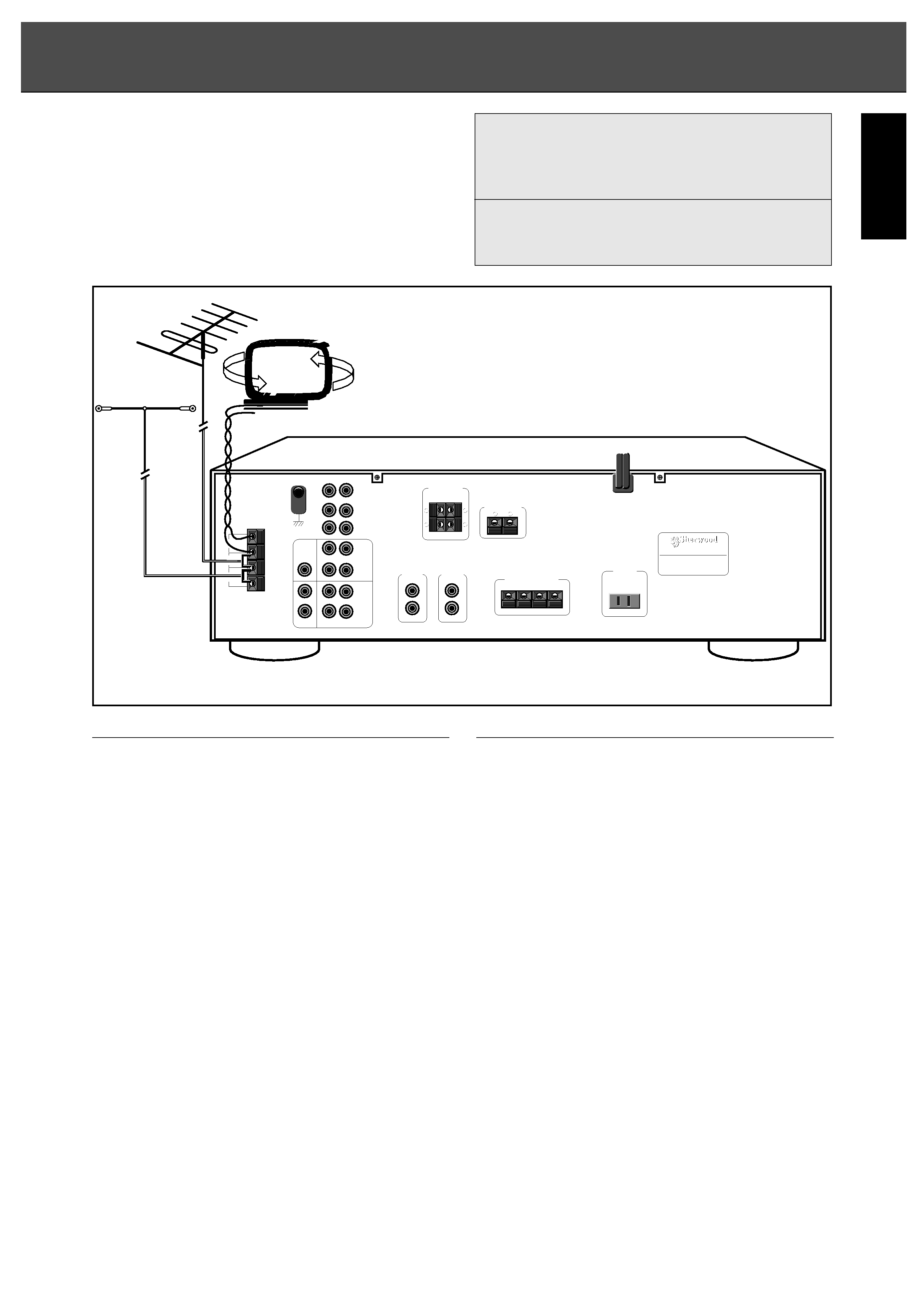
CONNECTIONS
A) FM INDOOR ANTENNA
Connect the supplied antenna to the FM antenna
terminals, as shown.
Change the position of the antenna until you get the best
reception of your favorite FM stations.
FM OUTDOOR ANTENNA
A 75 outdoor FM antenna may be used to further
improve the reception.
Disconnect the indoor antenna before replacing it with the
outdoor one.
B) AM LOOP ANTENNA
Tune in your favorite AM station and position the loop
antenna for best reception. Try other stations and find the
position that gives best overall reception. When this unit is
mounted in a rack or placed on a shelf with insufficient
space behind, hang the antenna on a wall in the direction
which gives best reception.
C) AUDIO IN/OUT
PHONO IN input jacks for connecting a turntable.
Connect these jacks to the OUTPUT jacks of the
turntable. The Phono EQ circuit in the receiver will
accommodate virtually all moving-magnet cartridges.
CD IN input jacks for connecting a Compact Disc player.
Connect these jacks to the OUTPUT jacks of the CD
player.
CONNECTIONS
TV/AUX IN input jacks for connecting the fixed audio
output of a TV set or any other source you want to hear; an
additional CD player, a cassette deck, a VCR or a
turntable with ceramic cartridge, etc.
TAPE PLAY/REC input and output jacks for connecting
a cassette deck, a Digital Compact Cassette deck or
another digital recording device.
Connect the PLAY jacks to the LINE OUTPUT jacks of
the deck.
These jacks may also be connected to the LINE
OUTPUT jacks of an audio processor such as an optional
graphic equalizer or a Digital Signal Processor.
Connect the REC jacks to the LINE INPUT jacks of the
deck.
These jacks may also be connected to the LINE INPUT
jacks of an audio processor such as an optional graphic
equalizer or a Digital Signal Processor.
VCR 1 PLAY/REC input and output jacks for connecting
the audio of a HiFi stereo VCR or any other A/V sourse.
Connect the PLAY jacks to the audio OUTPUT jacks of
the VCR.
Connect the REC jacks to the audio INPUT jacks of the
VCR.
3
ENGLISH
Important note for connecting equipment that does
not have IN/OUT markings on the input and output
jacks:
R-125
Device to be connected e.g. cassette deck.
PLAY
PLAY or OUT
REC
REC or IN
MODEL NO. R-125
AUDIO/VIDEO RECEIVER
MADE IN KOREA
DESIGNED IN USA
AM
LOOP
FM
300
MODEL NO. R-125
AUDIO/VIDEO RECEIVER
MADE IN KOREA
DESIGNED IN USA
AM
LOOP
FM
300
FM
75
FM
75
FM
FM
AM
+
-
+
-
+
-
+
-
+
-
+
-
(INDOOR ANTENNA)
(OUTDOOR ANTENNA)
NEW CASTLE
NEW CASTLE
INSTALLATION
SPEAKER POSITIONING
D) VIDEO IN/OUT
VCR 1 IN/OUT input and output jacks for connecting
the video input and output of a Audio Video device(e.g. a
HiFi VCR, laser disc, digital video disc or digital satellite
system).
MONITOR OUT output jack for connecting to the video
input of a TV set. The TV set must then be swiched to
that input.
E) SUBWOOFER Output jacks for connecting to a
separate amplifier or powerd
SUBWOOFER.
Connect SUBWOOFER output jacks to SUBWOOFER
input jacks of separate amplifier or inputs of a powered
SUBWOOFER.
F) REAR SPEAKERS
Terminals for connecting a pair of rear speakers,
impedance of 4 each, to obtain a surround sound
effect.
NOTE : Always connect two speakers to these terminals.
G) CENTER SPEAKER
Terminals for connecting a center speaker, impedance
8ohms.
H) FRONT SPEAKERS
Terminals for connecting a pair of speakers, impedance
8 ohms (L = left, R = right).
One of the wires of a loudspeaker cable is marked with
a colour or rib. Connect the marked wire to the red
terminal, the non-marked wire to the black one.
I) DIGI LINK
III SYSTEM CONTROL
(colored green) remote-control input/output jacks for
connection to the corresponding DIGI LINK
II or III jacks
of a Sherwood CD (Compact Disc) or tape player or a
remote control receiver. Connect this jack to the DIGI
LINK
III jack of the external equipment that uses the DIGI
LINK
II or III remote control system.
These jacks have been added to maintain compatibility
with other Sherwood products.
POWER
J) POWER LEAD
Connect the receivers AC power lead to an AC power
outlet (a surge protector is recommended).
K) OUTLETS
Switched output for connecting AC power plugs from
various units such as cassette deck, CD player, etc.
(Maximum capacity is 100 W).
Power supplied through this outlet is turned on and off by
the POWER button of the receiver.
CONNECTING HEADPHONES
Connect headphones with a 1/4"
plug to the PHONES jack.
Inserting the plug will not
disconnect the loudspeakers.
Turn the speakers off by
pressing the SPEAKER switch
once, press again to turn
speakers on. Also ensure
receiver is not in surround
modes.
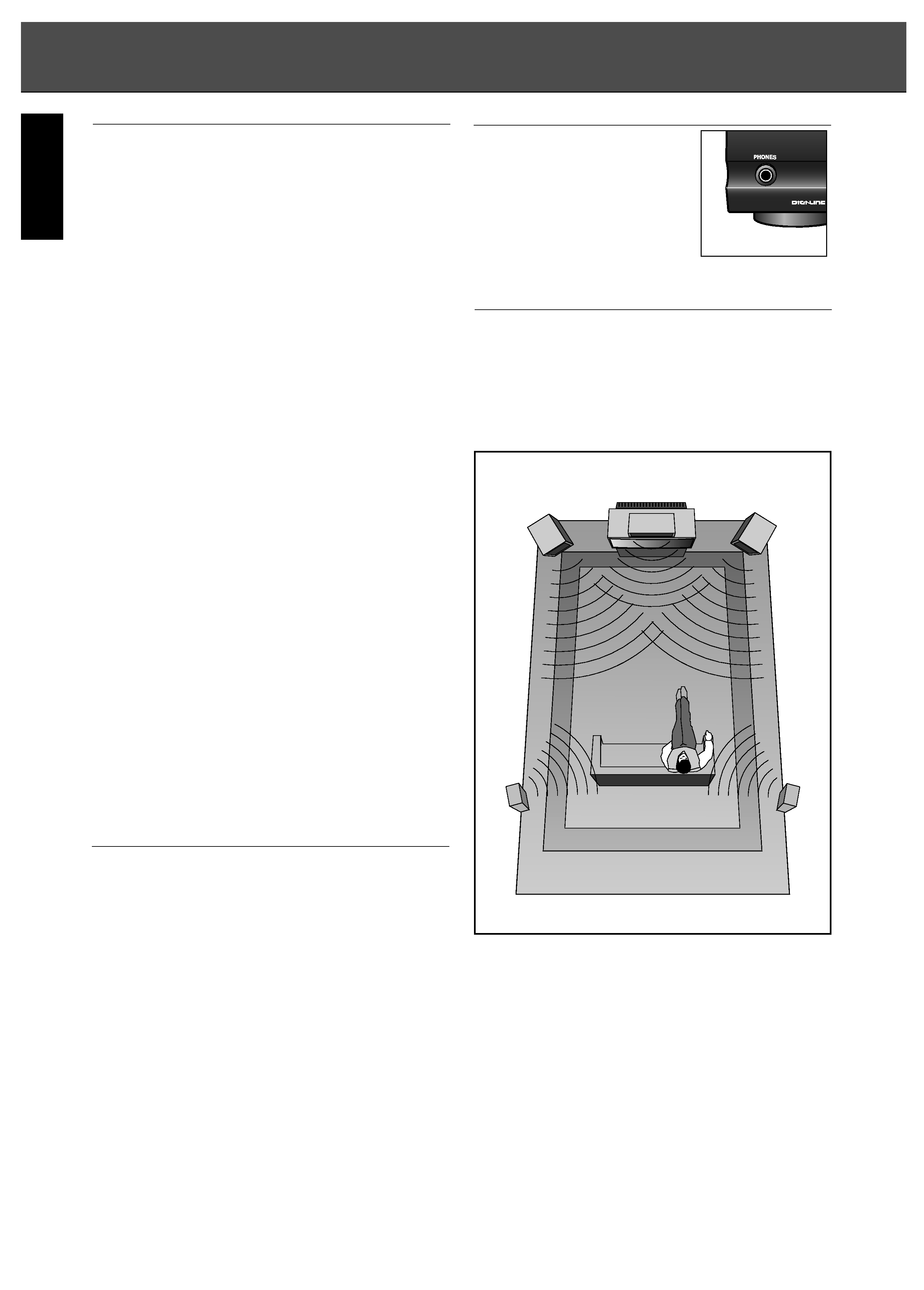
SPEAKER POSITIONING
To obtain the best surround sound effect in your home,
place the speakers as shown below.
The left and right speakers should be about 1 m (40") from
the TV set.
The center speaker should be above or below the TV set.
The rear speakers should be placed 2-3ft. above the ear
level of a seated listener on the direct left and right of them.
Refer to fold-out for additional information.
Note : to avoid interference with the TV picture, use only
magnetically shielded front speaker systems.
After making all necessary connections (some may not
apply to your system set-up), your system is ready for use.
In the next chapter, we will describe how to operate your
R-125 receiver.
4
LEFT
TV
RIGHT
CENTER
SPEAKER
SURROUND
LEFT
SURROUND
RIGHT
ENGLISH
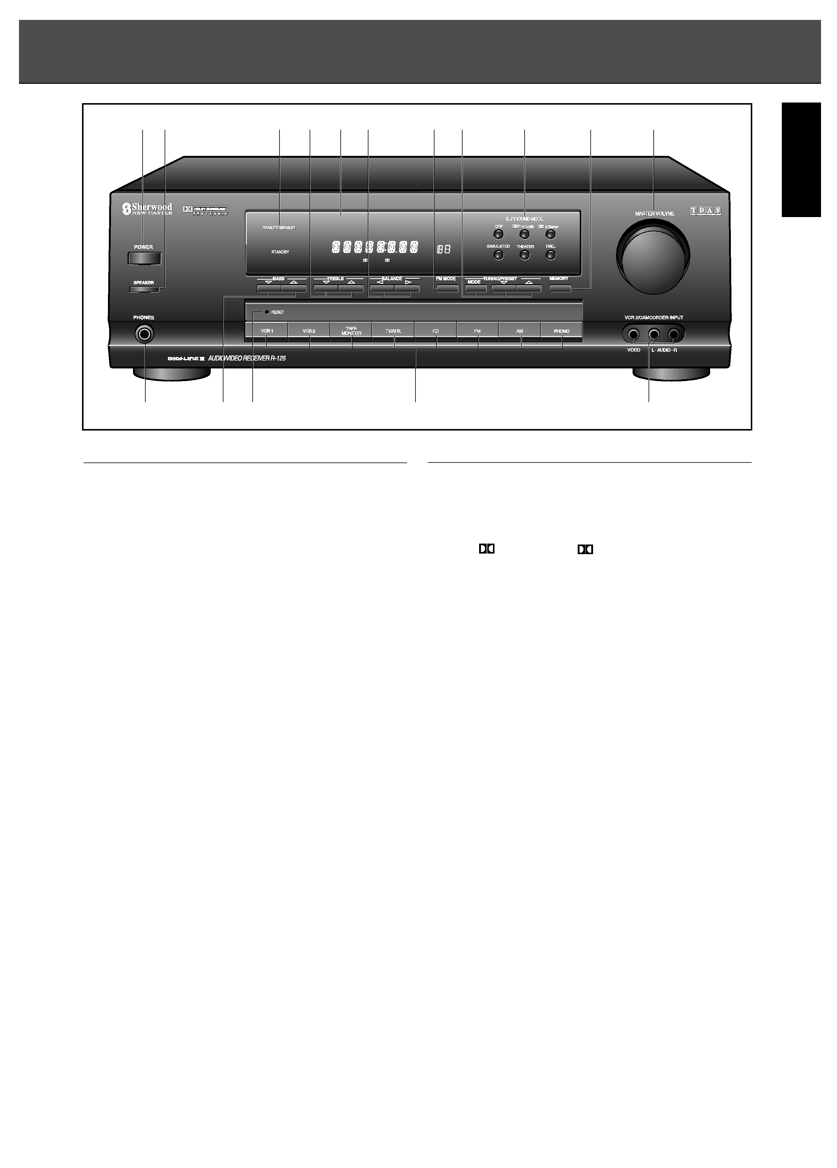
FUNCTIONAL OVERVIEW
FRONT PANEL
11.POWER ON/OFF
For switching the unit on and off.
12. SPEAKER
For switching the speakers connected to the FRONT
SPEAKER terminals on and off.
13. PHONES
For connecting headphones.
14.REMOTE SENSOR
Infrared remote control sensor for receiving signals from
the remote control.
15. FLUORESCENT DISPLAY
Informs you about the function of the receiver.
16.RESET
For resetting the unit in case of malfunction.
Press RESET for more than 5 seconds after switching
off.
17.BASS (
/
)
For adjusting the bass tones.
18.TREBLE (
/
)
For adjusting the high tones.
19.BALANCE (
/
)
For adjusting the balance of the volume between the left
and right channels.
10.FM MODE
For selecting STEREO or MONO operation in FM mode.
11.TUNING/PRESET
MODE : For selecting the frequency or preset mode.
/
: For adjusting the station frequency or selecting
the next/previous tuner preset.
/
: (use together with the MODE button)
FRONT
12. MEMORY
For storing preset stations.
13.SURROUND MODE
For selecting the surround mode.
OFF,
PRO LOGIC,
3 STEREO, SIMULATED,
THEATER, HALL
"Dolby", "Pro Logic" and the double D symbol are trademarks of Dolby
Laboratories Licensing Corporation. Manufactured under license from
Dolby Laboratories Licensing Corporation. Additionally licensed under
canadian patent number 1,037,877.
14.SOURCE SELECTION
For selecting the required audio or video source.
15.MASTER VOLUME
For adjusting the main volume.
16.VCR 2/CAMCORDER AUDIO/VIDEO INPUT
Connections for an exira VCR, camcorder, video game
or dss system The Audio jacks may also be used for an
extra audio source like a CD player or cassette.
5
RDS RT TIMER12 ST TUNED AUTO VCR12V-CD TAPE 2 M PRESET
EON TP TA PTY
Pro Logic
3 Stereo THEATER HALL
SLEEP
dB
kHz
MHz
MEM
ms
1 2
4
8
5
9
10 11
13
12
15
16
14
6
7
3
ENGLISH